


AreaRAE Plus & AreaRAE Pro
User’s Guide
Rev B
July 2017
P/N: W01-4001-000
Product Registration
Register your product online by visiting:
http://www.raesystems.com/support/product-registration
By registering your product, you can:
Receive notification of product upgrades or enhancements
Be alerted to Training classes in your area
Take advantage of RAE Systems special offers and promotions
IMPORTANT! BUMP TEST THE MONITOR BEFORE EACH DAY’S USE
Prior to each day’s use, every gas detection monitor should be bump tested to confirm the response of all sensors and activation of all alarms by exposing the monitor to a concentration of target gas that exceeds the low alarm set point. A bump test is also recommended if the monitor has been subjected to physical impact, liquid immersion, an Over Limit alarm event, or custody changes, or anytime the monitor’s performance is in doubt.
To ensure greatest accuracy and safety, only bump test and calibrate in a fresh air environment.
The monitor should be calibrated every time it does not pass a bump test, but no less frequently than every six months, depending on use and exposure to gas and contamination, and its operational mode.
•Calibration intervals and bump test procedures may vary due to national legislation.
•Honeywell recommends using calibration gas cylinders containing the gas that is appropriate to the sensor you are using, and in the correct concentration.
© 2017 RAE Systems by Honeywell.
AreaRAE Plus & AreaRAE Pro User’s Guide
Contents
1 |
Features Comparison .......................................................................................................................... |
15 |
|
2 |
Standard Contents ............................................................................................................................... |
16 |
|
3 |
General Information............................................................................................................................ |
17 |
|
|
3.1 |
Key Features ............................................................................................................................. |
18 |
4 |
Connections ........................................................................................................................................ |
19 |
|
5 |
User Interface...................................................................................................................................... |
20 |
|
|
5.1 |
Display Overview ..................................................................................................................... |
20 |
|
|
5.1.1 Status Indicator Icons ...................................................................................................... |
20 |
|
|
5.1.2 Status Indicator Icons For Instruments Equipped with ISM Radio or Wi-Fi.................. |
22 |
|
5.2 |
Keys And Interface ................................................................................................................... |
23 |
|
|
5.2.1 Reverse Direction............................................................................................................ |
23 |
|
5.3 |
Screen Display For Various Numbers Of Active Sensors ........................................................ |
24 |
|
5.4 |
Glance Mode ............................................................................................................................. |
24 |
|
|
5.4.1 Enter Glance Mode ......................................................................................................... |
24 |
|
|
5.4.2 Screens ............................................................................................................................ |
24 |
|
|
5.4.3 Exit Glance Mode ........................................................................................................... |
24 |
|
5.5 |
Menus........................................................................................................................................ |
25 |
|
|
5.5.1 Operation Mode Navigation............................................................................................ |
25 |
6 |
Wireless Operation ............................................................................................................................. |
26 |
|
|
6.1 |
Broadcast On Alarm And Remote Unit Sleep/Wakeup ............................................................ |
26 |
|
|
6.1.1 Send Message.................................................................................................................. |
28 |
|
|
6.1.2 Broadcast Message.......................................................................................................... |
30 |
|
|
6.1.3 View Messages In AreaRAE Plus/Pro ............................................................................ |
31 |
|
|
6.1.4 Wake Unit Up/Put Unit To Sleep.................................................................................... |
32 |
|
|
6.1.5 Wake Unit Up (At Instrument)........................................................................................ |
32 |
|
|
6.1.6 Wake Unit Up (From ProRAE Guardian)....................................................................... |
33 |
|
|
6.1.7 Put Unit To Sleep (From ProRAE Guardian) ................................................................. |
34 |
7 |
Wireless Control And Submenus........................................................................................................ |
35 |
|
|
7.1 |
ISM Settings.............................................................................................................................. |
36 |
8 |
Wi-Fi Settings ..................................................................................................................................... |
37 |
|
|
8.1 |
Secure Wireless Access Point Configuration............................................................................ |
37 |
|
8.2 |
Setting Wi-Fi Communication Parameters In ProRAE Studio II ............................................. |
38 |
|
|
8.2.1 Wi-Fi Power .................................................................................................................... |
39 |
|
|
8.2.2 Address............................................................................................................................ |
39 |
|
|
8.2.3 Channels And Security.................................................................................................... |
39 |
|
|
8.2.4 Security Mode ................................................................................................................. |
39 |
|
|
8.2.5 Security Key.................................................................................................................... |
40 |
|
|
8.2.6 SSID ................................................................................................................................ |
40 |
|
|
8.2.7 Server IP.......................................................................................................................... |
40 |
|
|
8.2.8 Server Port....................................................................................................................... |
40 |
9 |
Relays For Controlling External Equipment....................................................................................... |
41 |
|
10 |
Battery................................................................................................................................................. |
43 |
|
|
10.1 |
Charging.................................................................................................................................... |
43 |
|
10.2 |
Battery States ............................................................................................................................ |
44 |
|
10.3 |
External Battery Charger .......................................................................................................... |
44 |
|
|
10.3.1 External Battery Charger LED Indicators.................................................................... |
45 |
11 |
Turning The AreaRAE Plus/Pro On And Off..................................................................................... |
46 |
|
|
11.1 |
Turning The AreaRAE Plus/Pro On ......................................................................................... |
46 |
|
|
11.1.1 Pausing To View Screens During Startup.................................................................... |
46 |
|
11.2 |
Turning The AreaRAE Plus/Pro Off......................................................................................... |
46 |
|
11.3 |
Testing Alarm Indicators .......................................................................................................... |
47 |
|
11.4 |
Pump Status .............................................................................................................................. |
47 |
|
11.5 |
Calibration Status...................................................................................................................... |
47 |
3
AreaRAE Plus & AreaRAE Pro User’s Guide
11.6 |
Bump Status .............................................................................................................................. |
48 |
|
12 Programming |
...................................................................................................................................... |
49 |
|
12.1 Enter Programming ..........................................................................................In Basic Mode |
49 |
||
12.2 Enter Programming ...................................................................................In Advanced Mode |
50 |
||
12.3 |
Menus And ..............................................................................................................Submenus |
51 |
|
|
12.3.1 .......................................................... |
Editing And Selecting Parameters And Sensors |
51 |
|
12.3.2 .................................................................................................................... |
Calibration |
52 |
|
...................................................................................................... |
12.3.2.1. Fresh Air |
52 |
|
....................................................................................... |
12.3.2.2. Multi Sensor Span |
52 |
|
....................................................................................... |
12.3.2.3. Single Sensor Zero |
53 |
|
................................................................... |
12.3.2.4. Single Sensor Span Calibration |
54 |
|
................................................................ |
12.3.2.5. Single Sensor Span 2 Calibration |
55 |
|
...................................................................................... |
12.3.2.6. Multi Sensor Bump |
55 |
|
.................................................................................... |
12.3.2.7. Single Sensor Bump |
56 |
|
............................................................................................. |
12.3.2.8. Cal. Reference |
57 |
|
.......................................................................................... |
12.3.2.9. Change Cal. Gas |
57 |
|
.......................................................................................... |
12.3.2.10. Multi Cal. Select |
57 |
|
..................................................................................... |
12.3.2.11. Change Span Value |
58 |
|
.................................................................................. |
12.3.2.12. Change Span 2 Value |
58 |
|
12.3.3 .......................................................................................... |
LEL Calibration Procedure |
59 |
|
............................................. |
12.3.3.1. Zero Sensor Calibration For The LEL Sensor |
59 |
|
........................................................ |
12.3.3.2. Span Calibration For The LEL Sensor |
59 |
|
12.3.4 ................................................................................................................ |
Measurement |
60 |
|
.............................................................................................. |
12.3.4.1. Sensor On/Off |
60 |
|
....................................................................................... |
12.3.4.2. Change Meas. Gas |
61 |
|
....................................................................................... |
12.3.4.3. Measurement Unit |
61 |
|
12.3.5 .......................................................................................................................... |
Alarms |
63 |
|
................................................................................................ |
12.3.5.1. Alarm Limits |
63 |
|
................................................................................................. |
12.3.5.2. Alarm Mode |
63 |
|
............................................................................................. |
12.3.5.3. Alarm Settings |
63 |
|
.............................................................................................. |
12.3.5.4. Comfort Beep |
63 |
|
12.3.6 ......................................................................................................................... |
Datalog |
64 |
|
............................................................................................... |
12.3.6.1. Clear Datalog |
64 |
|
........................................................................................... |
12.3.6.2. Datalog Interval |
64 |
|
.......................................................................................... |
12.3.6.3. Sensor Selection |
64 |
|
.............................................................................................. |
12.3.6.4. Data Selection |
65 |
|
............................................................................................... |
12.3.6.5. Datalog Type |
65 |
|
.................................................................................... |
12.3.6.6. Memory Full Action |
66 |
|
12.3.7 ....................................................................................................................... |
Wireless |
67 |
|
................................................................................... |
12.3.7.1. Select Primary Radio |
67 |
|
.............................................................................................................. |
12.3.7.2. GPS |
67 |
|
............................................................................................................ |
12.3.7.3. Mesh |
68 |
|
.......................................................................................................... |
12.3.7.4. On/Off |
68 |
|
........................................................................................................ |
12.3.7.5. PAN ID |
68 |
|
........................................................................................................ |
12.3.7.6. Channel |
69 |
|
............................................................................................... |
12.3.7.7. Factory Reset |
69 |
|
12.3.8 .............................................................................................................................. |
ISM |
70 |
|
.............................................................................................. |
12.3.8.1. Power On/Off |
70 |
|
.................................................................................................. |
12.3.8.2. Network ID |
70 |
|
......................................................................................................... |
12.3.8.3. Unit ID |
71 |
|
12.3.9 ............................................................................................................................ |
Wi - Fi |
71 |
|
12.3.10 ..................................................................................................................... |
Message |
73 |
|
12.3.11 .....................................................................................................................Monitor |
73 |
|
|
............................................................................................... |
12.3.11.1. LCD Contrast |
73 |
4
AreaRAE Plus & AreaRAE Pro User’s Guide
|
|
|
12.3.11.2.Zero At Start ................................................................................................ |
74 |
|
|
|
12.3.11.3.Fast Startup .................................................................................................. |
74 |
|
|
|
12.3.11.4.Language ..................................................................................................... |
74 |
|
|
|
12.3.11.5.Site ID.......................................................................................................... |
74 |
|
|
|
12.3.11.6.User ID ........................................................................................................ |
74 |
|
|
|
12.3.11.7.Secure In Place ............................................................................................ |
75 |
13 |
User Modes......................................................................................................................................... |
|
78 |
|
|
13.1 |
Basic User Mode....................................................................................................................... |
78 |
|
|
13.2 |
Advanced User Mode................................................................................................................ |
78 |
|
14 |
Policy Enforcement ............................................................................................................................ |
78 |
||
|
14.1 |
Setting Policy Enforcement ...................................................................................................... |
78 |
|
|
14.2 |
Deactivating Policy Enforcement ............................................................................................. |
80 |
|
15 |
Calibration And Testing...................................................................................................................... |
82 |
||
|
15.1 |
Manual Alarms Test.................................................................................................................. |
82 |
|
|
15.2 |
Bump Testing And Calibration ................................................................................................. |
82 |
|
|
|
15.2.1 |
Bump (Functional) Testing .......................................................................................... |
82 |
|
|
15.2.2 Bias & Equilibration For Liquid O2 And Other Biased Sensors.................................. |
83 |
|
|
|
15.2.3 Testing The Gamma Radiation Sensor ........................................................................ |
84 |
|
|
|
15.2.4 Zero Calibration For Parts-Per-Billion (ppb) PID Sensor............................................ |
84 |
|
|
|
15.2.5 |
Fresh Air Calibration ................................................................................................... |
84 |
|
15.3 |
Span Calibration........................................................................................................................ |
85 |
|
|
15.4 |
Three-Point Calibration For Enhanced Linearity With Extended- |
|
|
|
|
Range And ppb PID Sensors .................................................................................................... |
85 |
|
|
|
15.4.1 VOC Zero Calibration Procedure For Enhanced Linearity With Extended- |
|
|
|
|
|
Range And ppb PID Sensors....................................................................................... |
86 |
|
|
15.4.2 Enabling 3-Point Calibration Via ProRAE Studio II ................................................... |
87 |
|
|
|
15.4.3 |
Calibration Setup ......................................................................................................... |
87 |
|
|
|
15.4.3.1. Using A T-Tube........................................................................................... |
87 |
|
|
|
15.4.3.2. Calibrating Without A T-Tube .................................................................... |
87 |
|
|
15.4.4 |
Multi-Sensor Span Calibration..................................................................................... |
88 |
|
|
15.4.5 |
Single-Sensor Span Calibration ................................................................................... |
89 |
16 Datalog Transfer, Monitor Configuration, and Firmware Upgrades Via Computer........................... |
90 |
|||
|
16.1 |
Downloading Datalogs And Performing PC-Based Instrument |
|
|
|
|
Configuration And Firmware Upgrades ................................................................................... |
90 |
|
17 |
Maintenance........................................................................................................................................ |
|
91 |
|
|
17.1 |
Removing/Installing The Rubber Boot ..................................................................................... |
91 |
|
|
17.2 |
Replacing The External Filter ................................................................................................... |
91 |
|
|
17.3 |
Removing/Cleaning/Replacing Sensor Modules ...................................................................... |
92 |
|
|
|
17.3.1 Handling, Storage, And Calibration Of HF and HCL Sensors .................................... |
93 |
|
|
|
17.3.2 |
Sensor Locations.......................................................................................................... |
94 |
|
17.4 |
Cleaning Or Replacing The PID ............................................................................................... |
94 |
|
|
|
17.4.1 Cleaning Or Replacing The 4R+ PID .......................................................................... |
95 |
|
|
|
17.4.2 Cleaning Or Replacing The 7R+ PID .......................................................................... |
97 |
|
|
|
|
17.4.2.1. Cleaning The PID Electrode Panel ............................................................ |
100 |
|
|
|
17.4.2.2. Cleaning The Lamp Housing Or Changing The Lamp.............................. |
100 |
|
17.5 |
Replacing The Sensor Compartment Cover............................................................................ |
102 |
|
|
17.6 |
Battery Removal/Replacement ............................................................................................... |
102 |
|
|
17.7 |
RAEMet Meteorological Sensor (Optional) ........................................................................... |
104 |
|
|
17.8 |
Antenna Installation ................................................................................................................ |
105 |
|
|
17.9 |
VOC Carbon Filter For CO Sensor......................................................................................... |
106 |
|
|
17.10 Exhaust Gas Collector For Diverting Output Or Collecting Gas Samples ......................... |
106 |
||
|
17.11 Base Plate For Tripod Mounting (Optional) ........................................................................... |
107 |
||
|
17.12 Replacing The Pump............................................................................................................... |
108 |
||
18 |
Alarms Overview.............................................................................................................................. |
110 |
||
5
AreaRAE Plus & AreaRAE Pro User’s Guide
|
18.1 |
Alarm Signals.......................................................................................................................... |
110 |
|
|
18.2 |
Changing The Alarm Mode .................................................................................................... |
110 |
|
19 |
Diagnostic Mode............................................................................................................................... |
111 |
||
|
19.1 |
Enter Diagnostic Mode ........................................................................................................... |
111 |
|
|
19.2 |
Adjusting Alarm LEDs & Buzzer ........................................................................................... |
111 |
|
|
19.3 |
Adjusting LCD Contrast ......................................................................................................... |
111 |
|
|
19.4 |
Pump Stall Threshold Adjustment .......................................................................................... |
111 |
|
|
|
19.4.1 Entering Diagnostic Mode To Set The Pump Stall Threshold................................... |
112 |
|
|
|
19.4.2 Selecting The Pump Stall Threshold Method ............................................................ |
112 |
|
|
|
19.4.3 Setting Pump Stall Threshold Values – Dynamic Method ........................................ |
113 |
|
|
|
19.4.4 Setting Pump Stall Threshold Values – Static Method.............................................. |
115 |
|
|
|
|
19.4.4.1. Stall High Threshold Setting – Static Method ........................................... |
115 |
|
|
|
19.4.4.2. Verifying the Stall High Setting ................................................................ |
116 |
|
|
|
19.4.4.3. Stall Low Threshold Setting - Static .......................................................... |
116 |
|
|
|
19.4.4.4. Verifying the Stall Low Setting - Static .................................................... |
116 |
|
19.5 |
Exit Diagnostic Mode ............................................................................................................. |
116 |
|
|
19.6 |
Alarm Signal Summary........................................................................................................... |
117 |
|
|
|
19.6.1 |
Hygiene Mode ............................................................................................................ |
117 |
|
|
19.6.2 |
General Alarms .......................................................................................................... |
118 |
20 |
Troubleshooting ................................................................................................................................ |
119 |
||
21 |
Specifications |
.................................................................................................................................... |
120 |
|
|
21.1 |
AreaRAE ..........................................................................Plus/Pro Wireless Configurations |
121 |
|
|
21.2 |
Sensor Specifications .............................................................................................................. |
122 |
|
22 |
Technical Support ............................................................................................................................. |
125 |
||
23 RAE Systems ..............................................................................................by Honeywell Contacts |
126 |
|||
6

AreaRAE Plus & AreaRAE Pro User’s Guide
 WARNINGS
Read Before Operating
This manual must be carefully read by all individuals who have or will have the responsibility of using, maintaining, or servicing this product. The product will perform as designed only if it is used, maintained, and serviced in accordance with the manufacturer’s instructions.
CAUTION!
Never operate the monitor when the cover is removed. Remove the monitor rear cover (gas plate cover) or battery only in an area known to be non-hazardous.
ANY RAPID UP-SCALE READING FOLLOWED BY A DECLINING OR ERRATIC READING MAY INDICATE A GAS CONCENTRATION BEYOND UPPER SCALE LIMIT, WHICH MAY BE HAZARDOUS.
TOUTE LECTURE RAPIDE ET POSITIVE, SUIVIE D’UNE BAISSE SUBITE OU ERRATIQUE DE LA VALEUR, PEUT INDIQUER UNE CONCENTRATION DE GAZ HORS GAMME DE DÉTECTION QUI PEUT ÊTRE DANGEREUSE
ONLY THE COMBUSTIBLE GAS DETECTION PORTION OF THIS INSTRUMENT HAS BEEN ASSESSED FOR PERFORMANCE.
UNIQUEMENT, LA PORTION POUR DÉTECTER LES GAZ COMBUSTIBLES DE CET INSTRUMENT A ÉTÉ ÉVALUÉE.
CAUTION: BEFORE EACH DAY’S USAGE, SENSITIVITY OF THE LEL SENSOR MUST BE TESTED ON A KNOWN CONCENTRATION OF METHANE GAS EQUIVALENT TO 20 TO 50% OF FULL-SCALE CONCENTRATION. ACCURACY MUST BE WITHIN 0 AND +20% OF ACTUAL. ACCURACY MAY BE CORRECTED BY CALIBRATION PROCEDURE.
ATTENTION: AVANT CHAQUE UTILISATION JOURNALIERE, VERIFIER LA SENSIBILITE DU CAPTEUR DE LIE AVEC UNE CONCENTRATION CONNUE DE METHANE EQUIVALENTE DE 20 A 50% DE LA PLEINE ECHELLE. LA PRECISION DOIT ETRE COMPRISE ENTRE 0 ET 20% DE LA VALEUR VRAIE ET PEUT ETRE CORRIGEE PAR UNE PROCEDURE D’ETALONNAGE.
CAUTION: HIGH OFF-SCALE READINGS MAY INDICATE AN EXPLOSIVE CONCENTRATION.
ATTENTION: DES LECTURES HAUTES ET HORS D’ECHELLE PEUVENT INDIQUER DES
CONCENTRATIONS DE GAZ INFLAMMABLES
CAUTION: SUBSTITUTION OF COMPONENTS MAY IMPAIR INTRINSIC SAFETY.
Note: Users are recommended to refer to ISA-RP12.13, Part II-1987 for general information on installation, operation, and maintenance of combustible gas detection instruments.
The AreaRAE Plus/Pro multi-gas detector must be calibrated if it does not pass a bump test, or at least once every 180 days, depending on use and sensor exposure to poisons and contaminants.
7
AreaRAE Plus & AreaRAE Pro User’s Guide
CAUTION!
TheAreaRAE, PGM-65XXX shall only be charged using a charger specifically supplied for use with the unit with a maximum output voltage of 12V, 7.5A, 60950-certified.
Use of non-RAE Systems components will void the warranty and can compromise the safe performance of this product.
MARKING
The PGM-65XXX is marked with the following information: RAE SYSTEMS
3775 N. 1st. St., San Jose CA 95134, USA
Type PGM-65XXX.
Serial No/barcode: XXXX-XXXX-XX
Cl.I Dv 2, Grps A,B,C,D T-Code T4.
C22.2 No.152-M1984
ANSI/ISA-12.13.01-2013
-20º C < Tamb < +50º C;
CAUTION: READ AND UNDERSTAND INSTRUCTION MANUAL BEFORE OPERATING OR SERVICING
ATTENTION: LIRE ET COMPRENDRE MANUEL D’INSTRUCTIONS AVANT D’UTILISER OU SERVICE.
FCC Part 15 Statement
This device complies with Part 15 of the FCC rules. Operation is subject to the following two conditions:
(1) This device may not cause harmful interference, and (2) this device must accept any interference received, including interference that may cause undesired operation.
Caution:
This device complies with Part 15 of the FCC Rules / Industry Canada license-exempt RSS standard(s). Operation is subject to the following two conditions: (1) this device may not cause harmful interference, and (2) this device must accept any interference received, including interference that may cause undesired operation.
Le présent appareil est conforme aux CNR d'Industrie Canada applicables aux appareils radio exempts de licence. L'exploitation est autorisée aux deux conditions suivantes : (1) l'appareil ne doit pas produire de brouillage, et (2) l'utilisateur de l'appareil doit accepter tout brouillage radioélectrique subi, même si le brouillage est susceptible d'en compromettre le fonctionnement.
Changes or modifications not expressly approved by the party responsible for compliance could void the user's authority to operate the equipment.
This equipment has been tested and found to comply with the limits for a Class B digital device, pursuant to part 15 of the FCC Rules. These limits are designed to provide reasonable protection against harmful interference in a residential installation. This equipment generates uses and can radiate radio frequency
8
AreaRAE Plus & AreaRAE Pro User’s Guide
energy and, if not installed and used in accordance with the instructions, may cause harmful interference to radio communications. However, there is no guarantee that interference will not occur in a particular installation. If this equipment does cause harmful interference to radio or television reception, which can be determined by turning the equipment off and on, the user is encouraged to try to correct the interference by one or more of the following measures:
—Reorient or relocate the receiving antenna.
—Increase the separation between the equipment and receiver.
—Connect the equipment into an outlet on a circuit different from that to which the receiver is connected.
—Consult the dealer or an experienced radio/TV technician for help.
Under Industry Canada regulations, this radio transmitter may only operate using an antenna of a type and maximum (or lesser) gain approved for the transmitter by Industry Canada. To reduce potential radio interference to other users, the antenna type and its gain should be so chosen that the equivalent isotropically radiated power (e.i.r.p.) is not more than that necessary for successful communication.
Conformément à la réglementation d'Industrie Canada, le présent émetteur radio peut fonctionner avec une antenne d'un type et d'un gain maximal (ou inférieur) approuvé pour l'émetteur par Industrie Canada. Dans le but de réduire les risques de brouillage radioélectrique à l'intention des autres utilisateurs, il faut choisir le type d'antenne et son gain de sorte que la puissance isotrope rayonnée équivalente
(p.i.r.e.) ne dépasse pas l'intensité nécessaire à l'établissement d'une communication satisfaisante.
This device complies with Industry Canada’s licence-exempt RSSs. Operation is subject to the following two conditions:
(1)This device may not cause interference; and
(2)This device must accept any interference, including interference that may cause undesired operation of the device.
9
AreaRAE Plus & AreaRAE Pro User’s Guide
MPE Reminder
To satisfy FCC / IC RF exposure requirements, a separation distance of 20 cm or more should be maintained between the antenna of this device and persons during device operation.
To ensure compliance, operation at closer than this distance is not recommended.
Les antennes installées doivent être situées de facon à ce que la population ne puisse y être exposée à une distance de moin de 20 cm. Installer les antennes de facon à ce que le personnel ne puisse approcher à 20 cm ou moins de la position centrale de l’ antenne.
La FCC des éltats-unis stipule que cet appareil doit être en tout temps éloigné d’au moins 20 cm des personnes pendant son functionnement.
Only for detachable antennas:
This radio transmitter (identify the device by certification number, or model number if Category II) has been approved by Industry Canada to operate with the antenna types listed below with the maximum permissible gain and required antenna impedance for each antenna type indicated. Antenna types not included in this list, having a gain greater than the maximum gain indicated for that type, are strictly prohibited for use with this device.
MESH |
Freewave 900 |
Wi-Fi |
Freewave 2400 |
|
|
|
|
Gain of antenna: |
Gain of antenna: |
Gain of antenna: |
Gain of antenna: |
3.0dBi |
2.0dBi |
4.9dBi |
2.5dBi Max |
Type of antenna: |
Type of antenna: |
Type of antenna: |
Type of antenna: |
Omnidirectional |
Omnidirectional |
Omnidirectional |
Omnidirectional |
Impedance of |
Impedance of |
Impedance of |
Impedance of |
antenna: 50 ohms |
antenna: 50 ohms |
antenna: 50 ohms |
antenna: 50 ohms |
Le présent émetteur radio (identifier le dispositif par son numéro de certification ou son numéro de modèle s'il fait partie du matériel de catégorie II) a été approuvé par Industrie Canada pour fonctionner avec les types d'antenne énumérés ci-dessous et ayant un gain admissible maximal et l'impédance requise pour chaque type d'antenne. Les types d'antenne non inclus dans cette liste, ou dont le gain est supérieur au gain maximal indiqué, sont strictement interdits pour l'exploitation de l'émetteur.
MESH |
Freewave 900 |
Wi-Fi |
Freewave 2400 |
|
|
|
|
Gain d'antenne: |
Gain d'antenne: |
Gain d'antenne: |
Gain d'antenne: |
3.0dBi |
2.0dBi |
4.9dBi |
2.5dBi Max |
Type d'antenne: |
Type d'antenne: |
Type d'antenne: |
Type d'antenne: |
Omni-directional |
Omni-directional |
Omni-directional |
Omni-directional |
Impedance |
impédance |
impédance |
impédance |
d'antenne: 50ohm |
d'antenne: 50ohm |
d'antenne: 50ohm |
d'antenne: 50ohm |
10
AreaRAE Plus & AreaRAE Pro User’s Guide
Wireless Security Warning
Wireless data transmission can extend beyond your walls and can be received by anyone with a compatible adapter. Without proper protection, data can be compromised. Use the security features of all wireless equipment in your network.
Each AreaRAE Plus/Pro has a default name and password. You should change these to personalize them upon first installation, which lessens the potential security risk that an unauthorized user can change the configuration.
After all configuration activities are completed, verify the each AreaRAE Plus/Pro for function with the location software separately from the system in which it will be operating.
IMPORTANT!
Other Wi-Fi devices may transmit specific Wi-Fi messages that interfere with AreaRAE Plus/Pro and other wireless devices in a wirelessly networked system. You should not allow any untrusted Wi-Fi transmitters inside the area of location and in its proximity (approximately 50 meters).
11
AreaRAE Plus & AreaRAE Pro User’s Guide
Operation Area and Conditions
Hazardous Areas classified by Divisions
PGM-65XXX is intended to be used in hazardous areas classified for Class I Div. 2, within the temperature range of -20º C to +50º C, where gases of explosion groups A, B, C or D and temperature code T4 may be present.
INSTRUCTIONS FOR SAFE USE
WARNING: Read and understand instruction manual before operation or servicing.
AVERTISSEMENT: Lisez et comprenez le manual d’instructions avant d’utiliser ou d'effectuer l'entretien.
WARNING: Substitution of components may impact safety. AVERTISSEMENT: La substitution de composants peut compromettre la sécurité.
WARNING: To prevent ignition of a hazardous atmosphere, batteries must only be charged in an area known to be non-hazardous area in the ambient temperature range 0° C ≤ Tamb ≤ 40° C. Use only approved charger.
AVERTISSEMENT: Afin de prevenir l’inflammation d’atmosphères dangereuse, ne charger le jeu de batteries que dans des emplacement designés non dangereux a temperature ambiante 0°C ≤ Tamb ≤ 40°C Utilisez uniquement un chargeur approuvé.
WARNING: As a condition of certification, connection may not be made to the communication port when the Gas Detector is in the hazardous location unless the area is known not to be hazardous. AVERTISSEMENT: Comme condition de la certification, un connexion filaire ne peut pas être faite via le port de communication lorsque le détecteur de gaz est dans la zone dangereuse à moins que la zone soit connue pour ne pas être dangereuse.
WARNING: Li-Ion rechargeable battery: Only use approved battery pack: W01-3007-000 or W01- 3007-100.
AVERTISSEMENT: Batterie rechargeable Li-Ion: Utilisez uniquement des batteries approuvé: W01- 3007-000 ou W01-3007-100.
12

AreaRAE Plus & AreaRAE Pro User’s Guide
USE IN HAZARDOUS AREAS
Equipment which is intended for use in explosive atmospheres and which has been assessed and certified according to international regulations may be used only under specified conditions. The components may not be modified in any way.
(i)Connection must only be made to the Vdc input jack and to the USB communication port when the instrument is in non-hazardous location or unless the area is known to be non-hazardous.
(ii)The battery pack shall only be charged or replaced in a non-hazardous location.
(iii)The sensors shall only be replaced in a non-hazardous location.
(iv)The external connection to the PGM 65xxx shall be in accordance to control drawing W01 0901CTL. The external alarms that are to be connected to PGM 65xxx must be suitable for the hazardous location where they are mounted, and supplied from Class 2 power supply or equivalent. The wiring method shall be to local electrical code and installation are subject to acceptance by authority having jurisdiction.
The appropriate regulations for service and repair must be properly observed during such activities.
PGM-65XXX contains a connector for mounting of a wind sensor – RAEMet. This connector has a set of entity parameters that match the input entity parameters of RAEMet:
Uo: 5.2V; Po: 0.788W; Lo: 198μH; Co: 1000μF.
Keep all ports covered when they are not in use. This keeps moisture and debris out of the ports and contributes to the instrument’s safety.
Cover all ports when they are not in use
Proper Product Disposal At End Of Life
The Waste Electrical and Electronic Equipment (WEEE) directive (2002/96/EC) is intended to promote recycling of electrical and electronic equipment and their components at end of life. This symbol (crossed-out wheeled bin) indicates separate collection of waste electrical and electronic equipment in the EU countries. This product may contain one or more Nickelmetal hydride (NiMH), Lithium-ion, or Alkaline batteries. Specific battery information is given in this user guide. Batteries must be recycled or disposed of properly.
At the end of its life, this product must undergo separate collection and recycling from general or household waste. Please use the return and collection system available in your
country for the disposal of this product.
13
AreaRAE Plus & AreaRAE Pro User’s Guide
Sensor Specifications, Cross-Sensitivities, And Calibration Information
For information on sensor specifications, cross-sensitivities, and calibration information, refer to RAE Systems Technical Note TN-114: Sensor Specifications And Cross-Sensitivities (available for free download from www.raesystems.com/downloads/tech-notes). All specifications presented in this Technical Note reflect the performance of stand-alone sensors. Actual sensor characteristics may vary when the sensor is installed in different instruments. As sensor performance may change over time, specifications provided are for brand-new sensors.
14
AreaRAE Plus & AreaRAE Pro User’s Guide
1 Features Comparison
The AreaRAE Plus and AreaRAE Plus/Pro share many of the same features and the same housing. This user’s guide details all features, including those that are only available on the AreaRAE Plus/Pro (depending your instrument’s configuration it may be configured with a different number of sensors, different primary radio type, etc.).
The table below shows the features on the AreaRAE Plus and AreaRAE Plus/Pro.
|
|
AreaRAE Plus |
AreaRAE Pro |
|
|
(PGM-6520) |
(PGM-6560) |
Gas Sensors |
|
|
|
Number of Gas |
|
7 |
7 |
Sensor Slots |
|
|
|
|
|
|
|
VOC |
|
7R+ 10.6eV Lamp PID (0.1ppm) |
7R+ 10.6eV Lamp PID (10 ppb) |
|
|
4R+ 10.6eV Lamp PID (0.1 ppm) |
4R+ 10.6eV Lamp PID (10 ppb) |
|
|
4R+ 9.8eV Lamp PID (1 ppm) |
4R+ 9.8eV Lamp PID (1 ppm) |
|
|
|
|
Combustible |
|
LEL |
LEL |
NDIR CO2 Sensor |
|
CO2 |
CO2 |
Toxic EC |
|
Up to 6 |
Up to 6 |
Supported Sensors |
|
O2, CO, CO ext., CO & H2, |
O2, CO, CO ext., CO & H2, |
|
|
H2S, H2S ext., SO2, NO, NO2, |
H2S, H2S ext., SO2, NO, NO2, |
|
|
HCN, NH3, PH3, HCl, HF, |
HCN, NH3, PH3, HCl, HF, |
|
|
ETO-A, ETO-B, ETO-C, Cl2, |
ETO-A, ETO-B, ETO-C, Cl2, |
|
|
ClO2, H2 |
ClO2, H2 |
Other Sensors |
|
|
|
Gamma |
|
No |
Yes (optional) |
RAEMet (Wind |
|
Yes (optional) |
Yes |
Speed, Direction, |
|
|
|
Temperature, |
|
|
|
Relative Humidity) |
|
|
|
GPS |
|
Yes |
Yes |
|
|
|
|
Wireless |
|
|
|
Long Range |
ISM Band |
900/2400 MHz |
900/2400 MHz |
|
Wi-Fi |
Optional |
Optional |
Short Range |
Mesh |
915/868 MHz |
915/868 MHz |
|
|
|
|
RF Antenna |
|
Vertical Polarization, Spring |
Vertical Polarization, Spring |
|
|
Base |
Base |
Solid-State Relays |
|
Yes (3) |
Yes (3) |
15
AreaRAE Plus & AreaRAE Pro User’s Guide
2 Standard Contents
The AreaRAE Pro and AreaRAE Plus kit includes:
AreaRAE Pro or AreaRAE Plus monitor with sensors, battery, and wireless options as specified and protective rubber boot installed
USB communication cable
AC/DC power adapter (90-264VAC input) plus power cords
Spare rechargeable battery
3 Spare external filters
Phillips screwdriver
Flathead screwdriver
4R+ PID opening tool (if instrument is equipped with a PID sensor)
7R+ PID cover opening tool (if instrument is equipped with a PID sensor)
PID lamp removal tool (if instrument is equipped with a PID sensor)
Lamp-cleaning kit (isopropanol)
“T”-type calibration tube
QuickStart Guide
CD with documentation
CD with ProRAE Studio II instrument configuration and data management software
Calibration and test certificate
Optional accessories:
Exhaust Gas Collector (P/N: W01-3020-000)
Tripod Base Plate (P/N: W01-3018-000)
VOC filter for CO sensors, package of 5 (P/N: W01-3019-000)
16
AreaRAE Plus & AreaRAE Pro User’s Guide
3 General Information
Honeywell’s AreaRAE Plus/Pro is a wireless, transportable area monitor that can simultaneously detect toxic and combustible gases, carbon dioxide, volatile organic chemicals (VOCs), radiation and meteorological factors. Whether being used into a HazMat response, deploying it at a public venue or installed as part of a fence-line detection system — for hours, days or weeks at a time — the AreaRAE Plus/Pro gives you the right hazard intelligence so you can ensure safety for your teams and the general public.
The AreaRAE Plus/Pro also facilitates Industrial Fence-line monitoring and has the capability to trigger additional devices via relays.
Remote real-time monitoring of sensor data and alarm status is achieved via ProRAE Guardian software.
17

AreaRAE Plus & AreaRAE Pro User’s Guide
3.1Key Features
Up to seven gas sensors (PID, LEL, CO2, Toxics)
Dedicated radiation sensor slot – Gamma sensor
RAEMet station for wind speed and direction, ambient temperature, and relative humidity
Multiple onboard wireless options:
Primary radio: ISM (900/2400 MHz)/Wi-Fi
Secondary radio: Mesh
CID2 certified for U.S. and Canada
Standard GPS module
Relay outputs
On the field interchangeable gas sensor (4R+ Smart sensor)
Colored rubber boots
Spare rechargeable battery
External battery charger
108dB alarm buzzer
Wraparound LED alarm
Easy serviceability (access to pump/gas sensors/battery)
Large Screen and intuitive User interface using icon and text (translated)
User interface available in 9 languages: Brazilian Portuguese, Chinese, Dutch, English, French, German, Italian, Russian, Spanish
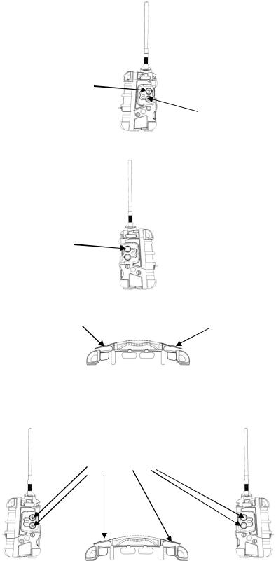
Antenna
RAEMet Meteorological Sensor (optional)
|
Alarm LEDs |
|
Alarm |
Alarm |
LEDs |
LED |
|
|
Display |
|
Charging and |
External filter |
USB ports |
And gas inlet |
(on side) |
|
Alarm buzzer |
[Y/+] key |
(on side) |
|
|
Alarm buzzer |
|
(on side) |
[N/-] key |
|
|
[MODE] key |
18 |
|
AreaRAE Plus & AreaRAE Pro User’s Guide
4 Connections
The AreaRAE Plus/Pro has six physical ports located on the left, right, and top sides. The rubber boot has integral caps for covering the ports when they are not in use.
USB for data transfer
Relay connector
RAEMet port
DC input for power and charging the internal battery
 Port for future features
Antenna port
IMPORTANT!
Keep all ports covered when they are not in use. This keeps moisture and debris out of the ports and contributes to the instrument’s intrinsic safety.
Cover all ports when they are not in use
19
AreaRAE Plus & AreaRAE Pro User’s Guide
5 User Interface
The AreaRAE Plus/Pro’s user interface consists of the display, alarm LEDs, an alarm buzzer, and three keys.
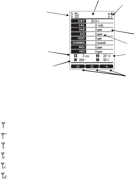
5.1 Display Overview
The LCD display provides visual feedback that includes the sensor types, readings, alarm status, battery condition, and other information.
Heading (changes with alarm, etc.)
Wireless radio on/off status, signal strength, active radio types and number, and GPS status
Installed, active  sensors
Wind speed
Wind direction (relative to 0° north orientation)
Status indicators ̶Datalog, battery
Pump, and “all sensors tested and calibrated according to policy” tick mark
 Reading
Alarm type (High, Low, etc.)
Unit of measure
Temperature
 Relative humidity
Soft keys (functions change by activity)
5.1.1Status Indicator Icons
Along the top of most screens are status indicators that tell you whether a function is operating and/or its strength or level.
Icon |
Function |
|
|
|
Wireless status: the ISM or Wi-Fi radio is on (blinks when it cannot find a network) |
|
|
|
Wireless status: the ISM or Wi-Fi radio is off |
|
|
|
ISM or Wi-Fi radio signal 0% to 19% |
|
|
|
ISM or Wi-Fi radio signal 20% to 39% |
|
|
|
ISM or Wi-Fi radio signal 40% to 79% |
|
|
|
ISM or Wi-Fi radio signal 80% to 100% |
|
|
ISM or |
Long-haul radio type (ISM or Wi-Fi) |
Wi-Fi |
|
|
|
RTR |
Number of Mesh Routers connected |
|
|
STD |
Number of standard mesh-radio devices connected |
|
|
|
20 |
AreaRAE Plus & AreaRAE Pro User’s Guide
GPS enabled and power is off
(flashing) Cannot find satellite
1 to 3 satellites
4 to 8 satellites
9 to 12 satellites
Pump operating normally (alternates between these two icons)
Pump blocked (blinks once per second)
Datalogging status (shown when datalogging is on, blank when off)
Battery voltage is ≥80%
Battery voltage is ≥50% and <80%
Battery voltage is ≥10% and <50%
Battery voltage is <10%
Battery error
Sensor due for calibration
Sensor due for a bump test
“All electrochemical sensors tested and calibrated to policy” tick mark (all sensors have been bump tested and calibrated; no sensor is overdue for a bump test or calibration according to the intervals configured on the instrument). This icon is not shown if any sensor is due for bump testing or calibration, or if policy enforcement is turned off
Wind speed
Wind direction
Temperature
Relative humidity
21

AreaRAE Plus & AreaRAE Pro User’s Guide
5.1.2Status Indicator Icons For Instruments Equipped with ISM Radio
or Wi-Fi
AreaRAE Plus/Pro instruments equipped with optional ISM radio or Wi-Fi use specific icons to indicate functionality.
Icon |
Description |
|
|
|
|
|
ISM or Wi-Fi power is off |
|
|
|
|
|
Cannot find network |
|
|
|
|
|
Received signal strength is |
|
|
>0 and <20% |
|
|
|
|
|
Received signal strength is |
|
|
≥20% and <40% |
|
|
|
|
|
Received signal strength is |
|
|
|
|
|
≥40% and <60% |
|
|
|
|
|
Received signal strength is |
|
|
≥60% and <80% |
|
|
|
|
|
Received signal strength is |
|
|
≥80% |
|
|
|
|
22
AreaRAE Plus & AreaRAE Pro User’s Guide
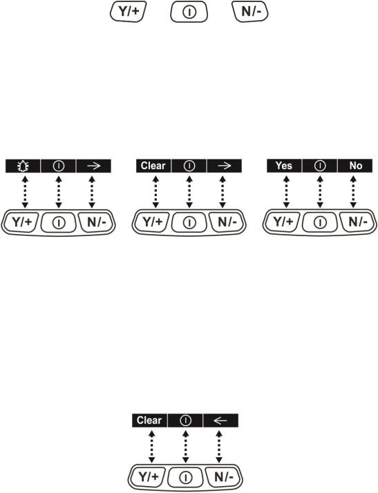
5.2 Keys And Interface
The AreaRAE Plus/Pro has three keys:
Y/+ |
MODE |
N/- |
In addition to their labeled functions, [Y/+], [MODE], and [N/-] act as “soft keys” that control different parameters and make different selections within the instrument’s menus. From menu to menu, each key controls a different parameter or makes a different selection.
Three panes along the bottom of the display are “mapped” to the keys. These change as menus change, but at all times the left pane corresponds to the [Y/+] key, the center pane corresponds to the [MODE] key, and the right pane corresponds to the [N/-] key. Here are examples that show the relationships of the keys and functions:
In addition to the functions described above, any of the keys can be used to manually activate display backlighting. Press any key when the backlighting is off to turn it on. A subsequent key press is required to carry out an actual function corresponding to that key.
5.2.1Reverse Direction
Sometimes you want to go back to a previous screen rather than advance through an entire set of screens before “wrapping around” to that screen again.
To reverse direction:
1.Press and hold [N/-] for 3 seconds.
2.When the arrow changes from pointing to the right to pointing to the left, release your finger.
Now when you press [N/-], you step back through the screens.
To change direction again: Press and hold [N/-] for 3 seconds and then release.
Note: Changing direction does not work with all screens. It works primarily in submenus.
23
AreaRAE Plus & AreaRAE Pro User’s Guide
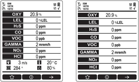
5.3 Screen Display For Various Numbers Of Active Sensors
The AreaRAE Plus/Pro can display readings from one to eight sensors, plus four meterology sensors (wind speed, wind direction, temperature, relative humidity) depending on the AreaRAE Plus/Pro’s configuration. In order to maximize readability and the amount of information shown, the display is automatically reconfigured, according to the number and types of sensors in the AreaRAE Plus/Pro.
8 Sensors with meteorology sensors |
8 sensors without meteorology sensors |
5.4 Glance Mode
Glance Mode allows you to get vital information without turning on the AreaRAE Plus/Pro. You can check information such as the instrument’s model and serial number, installed sensor types, wireless modules installed, etc., which may help when taking inventory of instruments and their sensors or when working with service or support personnel. Glance Mode can be enabled/disabled via ProRAE Studio II.
5.4.1Enter Glance Mode
Note: The instrument must be configured so that Glance Mode is turned on (the default mode is “Off”).
This can be done in ProRAE Studio II.
With the AreaRAE Plus/Pro turned off, press and hold [Y/+] to enter Glance Mode. The feature is latched, meaning that it runs even after you release the [Y/+] key. If you see the message “GLANCE DISABLED,” you must configure the instrument to use Glance Mode.
If Glance Mode is enabled, the first screen is displayed. After releasing [Y/+], other screens can be displayed by pressing the [N/-] Key. In ProRAE Studio II, Glance Mode can be enabled or disabled by checking or unchecking the box labeled “Enable Glance Mode.”
5.4.2Screens
Every screen displayed in sequence as configuration. Press [N/-] to advance to the next screen.
Press [MODE] to exit Glance Mode. The screens are shown in sequence.
5.4.3Exit Glance Mode
The AreaRAE Plus/Pro exits Glance Mode and turns off when you press the [MODE] key. In addition, if you do not press either key in 60 seconds, the AreaRAE Plus/Pro automatically exits Glance Mode.
24

AreaRAE Plus & AreaRAE Pro User’s Guide
5.5 Menus
The reading menus are easy to step through by pressing the [N/-] key.
Notes:
If the instrument is not equipped with a VOC sensor (PID), or is not equipped with an LEL sensor, then screens for those sensors (VOC Gas Status and LEL Gas Status, respectively) are not shown.
If ISM or Wi-Fi is not the primary modem, its menu is not displayed.
5.5.1Operation Mode Navigation
Note: Dashed line indicates automatic progression.
25
AreaRAE Plus & AreaRAE Pro User’s Guide
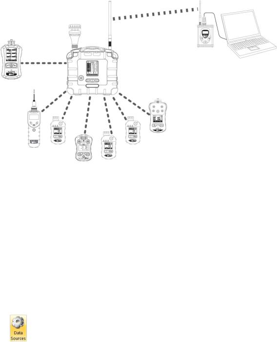
6 Wireless Operation
Depending on the wireless configuration of the instrument and which radio modules are active, the AreaRAE Plus/Pro can communicate directly through ISM-band radio to a RAELink3 wireless Host modem or via Wi-Fi to a Wi-Fi access point. In addition, the AreaRAE Plus/Pro is equipped with a Meshradio modem that communicates with Mesh-equipped instruments such as the MultiRAE, ToxiRAE Pro, etc., located up to 330 feet (100 meters) away. Up to eight of these instruments’ data can be relayed through the AreaRAE Plus/Pro to a PC running ProRAE Guardian to monitor them, as well as the AreaRAE Plus/Pro.
MultiRAE connected via Mesh radio to AreaRAE Plus/Pro
ISM
RAELink3 |
|
AreaRAE Plus/Pro Host |
PC running |
acts as access |
ProRAE |
point and relays data |
Guardian |
from connected |
|
wireless instruments |
|
MiniRAE 3000, QRAE 3, ToxiRAE Pro, and MicroRAE monitors connected via Mesh radio to AreaRAE Plus/Pro
Note: If the AreaRAE Pro or AreaRAE Plus is equipped with Wi-Fi, and Wi-Fi is used as the primary radio instead of ISM, then a Wi-Fi access point substitutes for the RAELink3 Host.
Note: The ISM radio acts as a repeater, providing extended range for other instruments operating with it.
Note: AreaRAE Plus/Pro can receive up to 10 different messages from a base station PC running ProRAE Guardian. The AreaRAE Plus/Pro can only receive a message from ProRAE Guardian when it is in Normal mode, and when no there are no active alarms.
6.1 Broadcast On Alarm And Remote Unit Sleep/Wakeup
Using ProRAE Guardian, you can control remote functions in the AreaRAE Plus/Pro.
1.Turn on your AreaRAE Plus/Pro.
2.Start ProRAE Guardian for your system.
3.Click “Data Sources.”
4.When the “Data Sources” window appears, check that the correct Serial Port is active.
26

AreaRAE Plus & AreaRAE Pro User’s Guide
5.Program the “Broadcast On Alarm” settings. Select “Broadcast on Alarm” to send a message to the entire system (via ISM or Wi-Fi) when an instrument goes into alarm. You can set the Alarm Interval to the time after each alert to be repeated (this is set in seconds; 2 seconds is the default value).
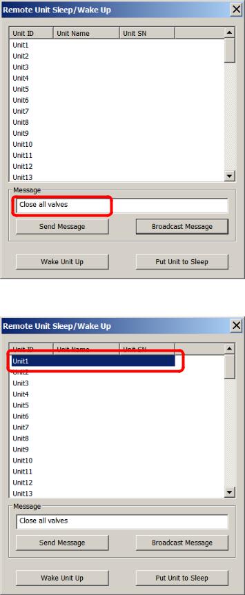
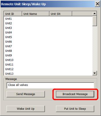
Click the “Remote Unit Sleep/Wakeup” button to access the screen with four buttons/functions:
Button |
Function |
Send Message |
Sends a message to a selected unit |
Broadcast Message |
Sends a message to all units on the same network |
Wake Unit Up |
Wakes up a selected unit that is currently in Sleep mode |
Put Unit To Sleep |
Puts a selected unit that is currently in Normal operation mode to sleep |
You can select specific units on the network to wake or put to sleep, as well as send a message that you type in the “Message” field.
27
AreaRAE Plus & AreaRAE Pro User’s Guide
6.1.1Send Message
Type a message that you want to send:
Click the name of an instrument that you want to send a message to:
28
AreaRAE Plus & AreaRAE Pro User’s Guide
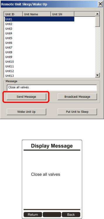
Click “Send Message.”
Any alarms (sound, lights) on the AreaRAE Plus/Pro will be triggered, and the message appears on its screen:
After 60 seconds, the message is cleared and the screen reverts to showing monitoring data.
Note: You can select multiple units to send to (Shift-Click to select sequential group, Control-Click to select individuals).
29
AreaRAE Plus & AreaRAE Pro User’s Guide
6.1.2Broadcast Message
From ProRAE Guardian, you can broadcast a message to all instruments on the network that accept messages.
1.Type a message into the “Message” field. Note: Each message is limited to 32 characters, including spaces.
2.Click “Broadcast Message.”
The message is broadcast to all instruments on the network that are capable of receiving messages.
30
 Loading...