


PS1201A00, PS1202A00 and PS2401A00 Replacement Power Supplies for Electronic Air Cleaners
INSTALLATION INSTRUCTIONS
APPLICATION
This power supply board has a selectable ionizer current output. Selection of the correct ionizer current is accomplished by moving the P5 shorting bar to the proper position. See table below.
Table 1.
|
|
|
|
|
Output Ionizer |
|
Input |
|
|
Output |
Current (mA) |
|
Voltage |
Input |
|
Ionizer |
(Selected by P5 |
Power |
Range |
Frequency |
Input |
Voltage |
shorting bar |
Supply |
(Vac) |
(Hz) |
Current (A) |
(Vdc) |
position) |
|
|
|
|
|
|
PS1201A00 |
102-132 Vac |
50 / 60 |
0.4 |
7500/ |
2.1/1.65/1.29/1.05*/ |
|
|
|
|
8150* |
0.9/0.25 |
|
|
|
|
|
|
PS1202A00 |
102-132 Vac |
50 / 60 |
0.4 |
7500/ |
2.1/1.65/1.29/1.05*/ |
|
|
|
|
8150* |
0.9/0.25 |
|
|
|
|
|
|
PS2401A00 |
204-264 Vac |
50 / 60 |
0.2 |
7500/ |
2.1/1.65/1.29/1.05*/ |
|
|
|
|
8150* |
0.9/0.25 |
|
|
|
|
|
|
*Default setting. |
|
|
|
|
|
69-2673EFS-01

PS1201A00, PS1202A00 AND PS2401A00 REPLACEMENT POWER SUPPLIES
Table 2.
|
|
|
|
|
|
|
|
Electronic Air Cleaner |
|
Nominal Size |
Ionizer |
Replacement |
|||
|
|
|
|
|
|
Current P5 |
Power Supply |
Model |
Voltage (Vac) |
|
In. |
Mm |
|||
|
Position (mA) |
|
|||||
|
|
|
|
|
|
|
|
|
|
|
|
|
|
|
|
F50F |
120 |
20 |
X 12.5 |
508 X 318 |
1.05* |
PS1201A00 |
|
|
|
|
|
|
|
|
|
|
|
16 |
X 20 |
406 |
X 508 |
1.29 |
|
|
|
|
|
|
|
|
|
|
|
16 x 25 |
406 |
X 635 |
1.65 |
|
|
|
|
|
|
|
|
|
|
|
|
20 x 20 |
508 |
X 508 |
1.65 |
|
|
|
|
|
|
|
|
|
|
|
|
20 x 25 |
508 |
X 635 |
2.1 |
|
|
|
|
|
|
|
|
|
|
|
240 |
20 |
X 12.5 |
508 X 318 |
1.05* |
PS2401A00 |
|
|
|
|
|
|
|
|
|
|
|
16 |
X 20 |
406 |
X 508 |
1.29 |
|
|
|
|
|
|
|
|
|
|
|
16 x 25 |
406 |
X 635 |
1.65 |
|
|
|
|
|
|
|
|
|
|
|
|
20 x 20 |
508 |
X 508 |
1.65 |
|
|
|
|
|
|
|
|
|
|
|
|
20 x 25 |
508 |
X 635 |
2.1 |
|
|
|
|
|
|
|
|
|
|
F300A,E |
120 |
20 |
X 12.5 |
508 X 318 |
1.05* |
PS1201A00 |
|
|
|
|
|
|
|
|
|
|
|
16 |
X 20 |
406 X 508 |
1.29 |
|
|
|
|
|
|
|
|
||
|
|
16 x 25 |
406 X 635 |
1.65 |
|
||
|
|
|
|
|
|
||
|
|
20 x 20 |
508 X 508 |
1.65 |
|
||
|
|
|
|
|
|
||
|
|
20 x 25 |
508 X 635 |
2.1 |
|
||
|
|
|
|
|
|
|
|
F300B |
240 |
20 |
X 12.5 |
508 X 318 |
1.05* |
PS2401A00 |
|
|
|
|
|
|
|
|
|
*Default setting. |
|
|
|
|
|
|
|
INSTALLATION
When installing this product…
1.Read these instructions carefully. Failure to follow them could damage the product or cause a hazardous condition.
2.Check the ratings given in the instructions and on the product to make sure the product is suitable for your application.
3.Installer must be a trained, experienced service technician.
4.After installation is complete, check out product operation as provided in these instructions.
CAUTION
Electric Shock Hazard. Can cause electrical shock or equipment damage. Disconnect power before installing replacement power supply.
69-2673EFS—01 |
2 |

PS1201A00, PS1202A00 AND PS2401A00 REPLACEMENT POWER SUPPLIES
STEP 1:
Remove old power supply and discard.
1 |
F50 |
2 |
|
M16638A
Fig. 1. Example
3 |
69-2673EFS—01 |

PS1201A00, PS1202A00 AND PS2401A00 REPLACEMENT POWER SUPPLIES
|
|
OR |
3 |
|
4 |
5 |
|
6 |
7 |
OR |
8 |
|
|
Fig. 2. Example
69-2673EFS—01 |
4 |

PS1201A00, PS1202A00 AND PS2401A00 REPLACEMENT POWER SUPPLIES
STEP 2:
Install new power supply.
BLACK COLLECTOR
|
|
|
|
|
|
|
RED IONIZER |
TEST |
|
|
|
|
|
|
|
|
BUTTON |
||
|
|
|
|
|
|
|
T1 |
RED |
|
BLACK |
P3 |
|
|
|
|
|
CONTACT |
||
|
|
|
|
|
|
|
|
||
|
|
|
|
|
|
|
|
|
BOARD |
4 |
|
|
|
|
|
|
|
BLACK |
|
|
|
|
U4 |
|
|
|
|
||
BLACK |
|
|
2 |
J8 |
|
|
|
||
|
|
7500V |
8150V |
0.9mA |
|
|
|||
|
|
|
|
|
|
|
|||
|
P4 |
|
|
|
|
P5 |
|
|
|
|
|
|
|
|
|
|
0.25mA |
|
|
|
7 |
P8 |
|
|
6 |
1.05mA |
|
|
|
|
|
|
1.29mA |
|
|
||||
|
J4 |
|
|
|
|
|
1.65mA |
|
|
|
|
|
|
|
|
2.1mA |
|
|
|
|
|
|
|
|
|
POWER SUPPLY |
|
|
|
|
5 |
|
3 |
|
|
|
P2 |
BROWN |
|
|
|
|
|
J4 |
|
|
|
||
|
R16 |
|
|
|
|
|
|||
|
J1 |
|
|
P1 |
|
|
|||
|
|
|
|
|
|
||||
|
|
|
|
|
|
|
BLACK |
|
|
|
JUMPER |
ORANGE |
|
|
|
|
|
|
|
GRAY |
|
|
|
|
|
|
|
|
|
|
|
|
|
|
|
|
|
|
VIOLET |
|
|
|
1 |
|
|
|
|
BLACK |
|
|
|
|
|
|
1 |
INTERLOCK SWITCH. |
|
|
|
|
|
|
|
|
|
|
|
|
|
|
||
2 |
SHORTING BAR FOR OZONE REDUCTION. |
W4 |
W2 |
W1 |
W3 |
BLACK |
BLACK |
|
|
|
|
BLACK |
WHITE |
||||
3 |
AIRFLOW SWITCH DISABLE JUMPER, R16. |
|
|
|
|
|
||
|
AIRFLOW SWITCH PLUG, J3. |
|
|
|
|
|
|
GREEN |
|
|
|
|
|
|
|
|
|
4 |
NEON LIGHT. |
|
|
|
|
|
|
|
5 |
|
AIRFLOW SWITCH BOARD |
|
|
|
|||
OPTIONAL W8600F AIR CLEANER MONITOR. |
|
|
|
|
|
|
||
GREEN
GROUND  CHOKE
CHOKE
6 JUMPER LOCATION FOR IONIZER CURRENT SELECTION.
7 JUMPER LOCATION FOR IONIZER VOLTAGE SELECTION. |
M32904A |
a.Position the P5 shorting bar for the size air cleaner you have.
b.Wire the power cord ground lead to the ground choke assembly using a wire nut. Secure ground connection to the green ground screw on the wiring compartment barrier.
CHECKOUT
With all components in place, turn on the air cleaner switch and energize the system blower. Check the following operation:
1.Be sure the neon light is on.
2.Turn off the system blower. The neon light should go off.
3.Turn the system blower back on. The neon light should come back on.
4.With the air cleaner energized, push the test button. A snapping sound indicates that collector section is energized.
5.With a multispeed blower, repeat steps 2 through 4.
6.If operation is not as described, refer to Troubleshooting and Service section.
5 |
69-2673EFS—01 |

PS1201A00, PS1202A00 AND PS2401A00 REPLACEMENT POWER SUPPLIES
TROUBLESHOOTING AND SERVICE
ELECTRONIC AIR CLEANER TROUBLESHOOTING GUIDE
START
MAKE SURE ELECTRONIC CELLS ARE CLEAN, DRY AND PROPERLY INSTALLED. MAKE SURE METAL PREFILTERS ARE POSITIONED ON THE SIDE WHERE
AIR ENTERS THE AIR CLEANER, AND THAT POST-FILTERS (IF ANY) ARE POSITIONED ON THE SIDE WHERE AIR LEAVES THE AIR CLEANER.
TURN THE POWER SWITCH ON THE AIR CLEANER ON, AND TURN THE HVAC FAN ON.
CHECK THE SYSTEM LIGHT |
OFF |
PUSH TEST BUTTON ON THE |
||||
ON THE AIR CLEANER. |
|
|
AIR CLEANER DOOR AND |
|||
ON |
|
|
|
LISTEN FOR SNAPPING SOUND. |
||
|
|
|
|
NO |
|
|
|
|
|
|
|
|
|
|
|
|
|
TURN OFF AIR CLEANER POWER |
||
PUSH TEST BUTTON ON THE |
NO |
|||||
SWITCH. REMOVE THE DOOR AND |
||||||
AIR CLEANER DOOR AND |
||||||
|
|
CHECK THAT THE CONTACTS ON |
||||
LISTEN FOR SNAPPING SOUND. |
|
|
||||
|
|
THE INSIDE OF THE TEST BUTTON |
||||
YES |
|
|
|
ARE OK. |
||
|
|
|
|
YES |
|
|
AIR CLEANER IS |
|
|
|
|||
FUNCTIONING PROPERLY. |
|
|
|
|
||
|
|
|
|
|||
TO USE THIS CHART:
1.FOLLOW THE STEPS IN ORDER; DO NOT SKIP AROUND.
2.EACH TIME A PROBLEM IS FIXED, GO BACK TO START.
3.REPEAT ALL THE STEPS UNTIL THE AIR CLEANER CHECKS OUT OK.
NOTE: IF A W8600F AIR CLEANER MONITOR IS CONNECTED TO THE AIR CLEANER, DISCONNECT THE AIR CLEANER FROM THE W8600F BEFORE STARTING THIS PROCEDURE. THE W8600F CAN BE CHECKED SEPARATELY. SEE W8600F INSTRUCTION SHEET.
YES
REPLACE LIGHT/SWITCH ASSEMBLY.
NO
REPAIR CONTACTS ON TEST BUTTON.
INSPECT THE CELLS FOR |
|
|
— BENT COLLECTOR PLATES |
|
|
— BROKEN IONIZER WIRES |
|
ON |
— DIRT ACCUMULATION ON |
|
|
THE INSULATORS |
|
|
|
|
|
— DAMAGED CONTACTS ON |
|
|
THE TERMINAL BOARD AT |
|
|
THE END OF THE CELL |
|
|
|
|
|
YES |
NO |
|
|
|
|
REPLACE OR |
|
|
REPAIR CELLS. |
|
|
|
|
|
|
|
|
WITH AN OHMMETER, CHECK
FOR SHORT BETWEEN:
—CELL FRAME AND IONIZER WIRES
—CELL FRAME AND COLLECTOR BLADES
|
|
|
|
|
|
|
SHORT |
|
|
NO |
|
|
|
DETECTED |
|
|
SHORT |
|
|
|
|
|
|
|
|
|
|
|
REPLACE |
|
CELLS OK. |
|||
|
CELLS. |
|
REPLACE AIR |
|||
|
|
|
|
CLEANER |
||
|
|
|
|
|||
|
|
|
|
POWER SUPPLY. |
||
REMOVE THE CELLS (LEAVE THE
PREFILTERS IN PLACE). CLOSE THE
ACCESS DOOR AND TURN ON THE
AIR CLEANER POWER SWITCH.
CHECK THE SYSTEM LIGHT
ON THE AIR CLEANER.
OFF
WARNING
THIS STEP EXPOSES
DANGEROUSLY HIGH VOLTAGE.
ONLY A QUALIFIED SERVICE
TECHNICIAN SHOULD ATTEMPT
THIS STEP.
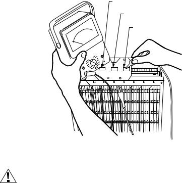
CHECK FOR CORRECT INPUT
VOLTAGE ACROSS P1 AND P2 NO FIX WIRING. TERMINALS ON POWER
SUPPLY BOARD.
YES
REPLACE AIR CLEANER
POWER SUPPLY.
THIS AIR CLEANER PRODUCES A TRACE LEVEL OF OZONE AS A BY-PRODUCT OF NORMAL OPERATION, WHICH IS WELL UNDER THE LIMIT PRESCRIBED BY THE U.S. F.D.A. PLEASE REFER TO YOUR OWNERS MANUAL FOR FURTHER INFORMATION. FOR A REPLACEMENT OWNERS MANUAL, CALL 1-800-468-1502 OR VISIT http://yourhome.honeywell.com
WARNING
INCORRECT CONVERSION TO MEDIA AIR CLEANER CAN CAUSE FIRE HAZARD.
WHEN CONVERTING AN ELECTRONIC AIR CLEANER TO A MEDIA AIR CLEANER THE POWER SUPPLY MUST BE REMOVED OR PERMANENTLY DISABLED.
M13656
69-2673EFS—01 |
6 |
PS1201A00, PS1202A00 AND PS2401A00 REPLACEMENT POWER SUPPLIES
Use an ohmmeter to check the electronic cells for short circuits.
COLLECTOR
TERMINAL
IONIZER
TERMINAL
COLLECTOR
TERMINAL
M6155A |
Modification to Reduce Ozone Odor
CAUTION
Electric Shock Hazard. Can cause personal injury.
Always disconnect power and open access door before opening power supply cover.
The electronic air cleaner generates a small amount of ozone in normal operation. During the first week or two of operation, the amount may be higher because of sharp edges on some of the new high voltage metal parts. Normal use quickly dulls these edges.
If desired, the ozone generated by the air cleaner can be reduced in one of two ways:
1.Install an activated carbon filter downstream from the air cleaner. Make sure particles from the air filter cannot fall into the air cleaner.
2.Move J8 shorting bar. This will reduce ozone production about 20 to 25 percent and reduce efficiency about seven to ten percent, depending on actual airflow delivered by the furnace blower.
a.Unplug or disconnect power supply to the air cleaner.
b.Open the access door.
c.Remove the power box cover.
d.Move J8 shorting bar. See figure below.
7 |
69-2673EFS—01 |

PS1201A00, PS1202A00 AND PS2401A00 REPLACEMENT POWER SUPPLIES
P3
J8 SHUNT |
J8 |
|
P4 |
||
IN OZONE |
||
|
||
REDUCTION |
|
|
POSITION |
|
|
|
J4 |
J8 IN
NORMAL
POSITION
J3
J1
P2

 P1
P1
M32906
Automation and Control Solutions
Honeywell International Inc. 1985 Douglas Drive North Golden Valley, MN 55422 customer.honeywell.com
® U.S. Registered Trademark
© 2013 Honeywell International Inc.
69-2673EFS—01 M.S. 09-13
Printed in United States
 Loading...