


 Loading...
N431X
Decoded Laser Scan Engine
User’s Guide
™

Disclaimer
Honeywell International Inc. (“HII”) reserves the right to make changes in specifications and other information contained in this document without prior notice, and the reader should in all cases consult HII to determine whether any such changes have been made. The information in this publication does not represent a commitment on the part of HII.
HII shall not be liable for technical or editorial errors or omissions contained herein; nor for incidental or consequential damages resulting from the furnishing, performance, or use of this material.
This document contains proprietary information that is protected by copyright. All rights are reserved. No part of this document may be photocopied, reproduced, or translated into another language without the prior written consent of HII.
© 2012 Honeywell International Inc. All rights reserved.
Web Address: www.honeywellaidc.com
Microsoft® Windows® and the Windows logo are trademarks or registered trademarks of Microsoft Corporation.
Other product names or marks mentioned in this document may be trademarks or registered trademarks of other companies and are the property of their respective owners.

Product Agency Compliance
Note: It is the OEM manufacturer’s responsibility to comply with applicable regulation(s) in regard to standards for specific equipment combinations.
Honeywell shall not be liable for use of our product with equipment (i.e., power supplies, personal computers, etc.) that is not CE marked and does not comply with the Low Voltage Directive.
For CE-related inquiries, contact:
Honeywell Imaging & Mobility Europe BV
Nijverheidsweg 9-13
5627 BT Eindhoven
The Netherlands
CB Scheme
IEC 60950-1:2005+Am1:2009
EN 60950-1:2006+A11:2009+A1:2010+A12:2011
 UL/C-UL (Recognized component)
UL 60950-1 Second Edition
CSA C22.2 No. 60950-1-07, 2nd Edition
LED Safety Statement
LEDs have been tested and classified as “EXEMPT RISK GROUP” to the standard IEC 62471:2006.
International
Laser Safety Statement
This device has been tested in accordance with and complies with IEC 60825-1 ed2.0.
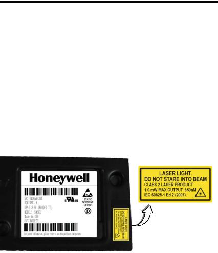
LASER LIGHT, DO NOT STARE INTO BEAM, CLASS 2 LASER PRODUCT, 1.0 mW MAX OUTPUT: 650nm.
Engine Laser Beam
Wavelength 650 nm
Max power output 1mW
The laser diode is considered an embedded laser. Intrabeam viewing of the laser shall be prevented.
Embedded Laser
Wavelength 650 nm
Max power output 10 mW
Caution - use of controls or adjustments or performance of procedures other than those specified herein may result in hazardous radiation exposure.
Patents
For patent information, please refer to www.honeywellaidc.com/patents.
Required Safety Labels
Shipping Container Labels
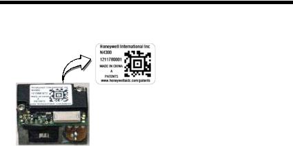
Product Label
ESD Precautions
The engine is shipped in ESD safe packaging. Use care when handling the scan engine outside its packaging. Be sure grounding wrist straps and properly grounded work areas are used.
Dust and Dirt
The engine must be sufficiently enclosed to prevent dust particles from gathering on the engine and lens. When stocking the unit, keep it in its protective packaging. Dust and other external contaminants will eventually degrade unit performance.
RoHS
The N43XX engine is in compliance with Directive 2002/95/EC, Restriction of the Use of Certain Hazardous Substances in Electrical and Electronic Equipment (RoHS), dated January, 2003.
 D-Mark Statement
Certified to EN 60950-1:2006+A11:2009+A1:2010+A12:2011 Information Technology Equipment product safety.


Table of Contents
Chapter 1 - Getting Started
Introduction ................................................................. |
1-1 |
About This Manual ...................................................... |
1-1 |
Unpacking Your Device............................................... |
1-1 |
Connecting the Development Engine to the PC.......... |
1-1 |
Reading Techniques ................................................... |
1-3 |
Menu Bar Code Security Settings ............................... |
1-4 |
Setting Custom Defaults ............................................. |
1-4 |
Resetting the Custom Defaults ................................... |
1-4 |
Resetting the Factory Defaults.................................... |
1-5 |
Chapter 2 - Programming the Interface |
|
Introduction ................................................................. |
2-1 |
Programming the Interface - Plug and Play ................ |
2-1 |
RS232 Serial Port.................................................. |
2-1 |
OPOS Mode .......................................................... |
2-1 |
USB IBM SurePos................................................. |
2-2 |
IBM Secondary Interface....................................... |
2-3 |
USB PC or Macintosh Keyboard ........................... |
2-3 |
USB HID................................................................ |
2-4 |
HID Fallback Mode................................................ |
2-4 |
USB Serial Commands ............................................... |
2-4 |
USB Serial Emulation............................................ |
2-4 |
CTS/RTS Emulation .............................................. |
2-5 |
ACK/NAK Mode..................................................... |
2-6 |
Communication Timeout ....................................... |
2-6 |
NAK Retries........................................................... |
2-7 |
Support BEL/CAN in ACK/NAK............................. |
2-7 |
Verifone® Ruby Terminal Default Settings .................. |
2-8 |
Gilbarco® Terminal Default Settings ........................... |
2-8 |
Wincor Nixdorf Terminal Default Settings ................... |
2-9 |
Wincor Nixdorf Beetle™ Terminal Default Settings..... |
2-9 |
Keyboard Country Layout ......................................... |
2-10 |
Keyboard Wedge Modifiers....................................... |
2-12 |
iii

ALT Mode ............................................................ |
2-12 |
Keyboard Style .................................................... |
2-12 |
Keyboard Conversion .......................................... |
2-13 |
Keyboard Modifiers.............................................. |
2-14 |
RS232 Modifiers ........................................................ |
2-16 |
RS232 Baud Rate................................................ |
2-16 |
RS232 Word Length: Data Bits, Stop Bits, |
|
and Parity ....................................................... |
2-17 |
RS232 Handshaking............................................ |
2-18 |
RS232 Timeout.................................................... |
2-19 |
XON/XOFF .......................................................... |
2-20 |
ACK/NAK ............................................................. |
2-20 |
Communication Timeout...................................... |
2-20 |
NAK Retries ......................................................... |
2-21 |
Support BEL/CAN in ACK/NAK ........................... |
2-22 |
RS232 Defaults.................................................... |
2-22 |
Chapter 3 - Input/Output Settings |
|
Power Up Beeper ........................................................ |
3-1 |
Beep on BEL Character............................................... |
3-1 |
Good Read and Error Indicators.................................. |
3-2 |
Beeper – Good Read............................................. |
3-2 |
Beeper Pitch – Good Read.................................... |
3-2 |
Beeper - Transmit Order........................................ |
3-3 |
Beeper Pitch – Error .............................................. |
3-3 |
Beeper Duration – Good Read .............................. |
3-3 |
Number of Beeps – Good Read ............................ |
3-4 |
Number of Beeps – Error....................................... |
3-4 |
LED Indicators ............................................................. |
3-4 |
LED Settings.......................................................... |
3-5 |
Activation Settings ....................................................... |
3-5 |
Activation Defaults ................................................. |
3-5 |
Presentation Modes............................................... |
3-6 |
Manual Activation Mode ........................................ |
3-6 |
End Manual Activation After Good Read ............... |
3-6 |
iv

Manual Activation Laser Timeout - |
|
External Trigger Settings ................................. |
3-7 |
CodeGate® ............................................................ |
3-8 |
Object Detection Mode.......................................... |
3-8 |
End Object Detection After Good Read ................ |
3-8 |
Object Detection Laser Timeout............................ |
3-9 |
Object Detection Distance..................................... |
3-9 |
Character Activation Mode........................................ |
3-10 |
Activation Character ............................................ |
3-10 |
End Character Activation After Good Read......... |
3-10 |
Character Activation Laser Timeout .................... |
3-11 |
Character Deactivation Mode.................................... |
3-11 |
Deactivation Character........................................ |
3-11 |
Reread Delay ............................................................ |
3-12 |
User-Specified Reread Delay.................................... |
3-12 |
Centering................................................................... |
3-13 |
Blinky Mode............................................................... |
3-13 |
Laser Scan Angle...................................................... |
3-14 |
Decode Security........................................................ |
3-14 |
Continuous Scan Mode............................................. |
3-14 |
Power Save Mode Timeout....................................... |
3-15 |
Power Save Mode..................................................... |
3-15 |
Aimer Control ............................................................ |
3-15 |
User-Specified Aimer Delays .............................. |
3-16 |
Output Sequence Overview ...................................... |
3-17 |
Require Output Sequence................................... |
3-17 |
Output Sequence Editor ...................................... |
3-17 |
To Add an Output Sequence............................... |
3-17 |
Other Programming Selections ........................... |
3-18 |
Output Sequence Editor ...................................... |
3-20 |
Sequence Timeout .............................................. |
3-20 |
Sequence Match Beeper..................................... |
3-20 |
Partial Sequence ................................................. |
3-20 |
Require Output Sequence................................... |
3-21 |
No Read .................................................................... |
3-22 |
v

Chapter 4 - Data Editing
Prefix/Suffix Overview.................................................. |
4-1 |
To Add a Prefix or Suffix:....................................... |
4-1 |
To Clear One or All Prefixes or Suffixes ................ |
4-2 |
To Add a Carriage Return Suffix to |
|
All Symbologies................................................ |
4-3 |
Prefix Selections .......................................................... |
4-3 |
Suffix Selections .......................................................... |
4-4 |
Transmit Alternate Extended ASCII Characters .......... |
4-4 |
Function Code Transmit .............................................. |
4-6 |
Communication Check Character................................ |
4-6 |
Intercharacter, Interfunction, and |
|
Intermessage Delays................................................. |
4-7 |
Intercharacter Delay .............................................. |
4-7 |
User Specified Intercharacter Delay ...................... |
4-7 |
Interfunction Delay................................................. |
4-8 |
Intermessage Delay............................................... |
4-9 |
Chapter 5 - Data Formatting |
|
Data Format Editor Introduction................................... |
5-1 |
Add a Data Format ...................................................... |
5-1 |
Other Programming Selections.............................. |
5-3 |
Terminal ID Table ........................................................ |
5-4 |
Data Format Editor Commands ................................... |
5-4 |
Move Commands................................................... |
5-8 |
Search Commands .............................................. |
5-10 |
Miscellaneous Commands................................... |
5-12 |
Data Formatter........................................................... |
5-15 |
Data Format Non-Match Error Tone .................... |
5-16 |
Primary/Alternate Data Formats ................................ |
5-17 |
Single Scan Data Format Change ....................... |
5-17 |
Chapter 6 - Symbologies |
|
All Symbologies ........................................................... |
6-1 |
Message Length Description ....................................... |
6-2 |
vi
Codabar ...................................................................... |
6-3 |
Codabar Concatenation ........................................ |
6-4 |
Code 39....................................................................... |
6-6 |
Code 32 Pharmaceutical (PARAF)........................ |
6-8 |
Full ASCII .............................................................. |
6-9 |
Interleaved 2 of 5 ...................................................... |
6-10 |
NEC 2 of 5................................................................. |
6-12 |
Code 93..................................................................... |
6-14 |
Straight 2 of 5 Industrial (three-bar start/stop) .......... |
6-15 |
Straight 2 of 5 IATA (two-bar start/stop).................... |
6-17 |
Matrix 2 of 5 .............................................................. |
6-18 |
Code 11..................................................................... |
6-20 |
Code 128................................................................... |
6-23 |
ISBT 128 ................................................................... |
6-24 |
GS1-128.................................................................... |
6-30 |
Telepen ..................................................................... |
6-32 |
UPC-A ....................................................................... |
6-34 |
UPC-A/EAN-13 with Extended Coupon Code........... |
6-37 |
UPC-A/Code 128 Coupon Code Output.............. |
6-37 |
UPC-A Number System 4 Addenda Required .... |
6-38 |
UPC-A Number System 5 Addenda Required .... |
6-38 |
UPC-E0 ..................................................................... |
6-40 |
EAN/JAN-13.............................................................. |
6-44 |
EAN-13 Beginning with 2 Addenda Required ..... |
6-45 |
EAN-13 Beginning with 290 Addenda Required . 6-46 |
|
EAN-13 Beginning with 378/379 Addenda |
|
Required ........................................................ |
6-46 |
EAN-13 Beginning with 414/419 Addenda |
|
Required ........................................................ |
6-47 |
EAN-13 Beginning with 434/439 Addenda |
|
Required ........................................................ |
6-48 |
EAN-13 Beginning with 977 Addenda Required . 6-49 |
|
EAN-13 |
Beginning with 978 Addenda Required . 6-49 |
|
EAN-13 |
Beginning with 979 Addenda Required . 6-50 |
|
ISBN Translate .................................................... |
6-52 |
|
ISSN Translate .................................................... |
6-53 |
|
EAN/JAN-8 |
................................................................ |
6-54 |
vii

MSI ............................................................................ |
6-57 |
Plessey Code............................................................. |
6-59 |
GS1 DataBar Omnidirectional ................................... |
6-61 |
GS1 DataBar Limited................................................. |
6-62 |
GS1 DataBar Expanded ............................................ |
6-63 |
Trioptic Code ............................................................. |
6-64 |
GS1 Emulation........................................................... |
6-65 |
Postal Codes ............................................................. |
6-65 |
China Post (Hong Kong 2 of 5)............................ |
6-66 |
Chapter 7 - Interface Keys |
|
Keyboard Function Relationships ................................ |
7-1 |
Supported Interface Keys ............................................ |
7-2 |
Chapter 8 - Utilities |
|
To Add a Test Code I.D. Prefix to All Symbologies ..... |
8-1 |
Show Software Revision.............................................. |
8-1 |
Show Data Format....................................................... |
8-1 |
Test Menu.................................................................... |
8-2 |
EZConfig-Scanning Introduction.................................. |
8-2 |
Installing EZConfig-Scanning from the Web.......... |
8-3 |
Chapter 9 - Serial Programming Commands |
|
Conventions................................................................. |
9-1 |
Menu Command Syntax .............................................. |
9-1 |
Query Commands........................................................ |
9-1 |
Responses............................................................. |
9-2 |
Serial Trigger Commands............................................ |
9-3 |
Read Time-Out ...................................................... |
9-4 |
Resetting the Standard Product Defaults .................... |
9-4 |
Menu Commands ........................................................ |
9-5 |
Chapter 10 - Maintenance |
|
Repairs ...................................................................... |
10-1 |
Maintenance .............................................................. |
10-1 |
viii

Inspecting Cords and Connectors ....................... |
10-1 |
Troubleshooting ........................................................ |
10-1 |
Chapter 11 - Customer Support |
|
Technical Assistance ................................................ |
11-1 |
Appendix A - Reference Charts |
|
Symbology Charts....................................................... |
A-1 |
Linear Symbologies............................................... |
A-1 |
Postal Symbologies............................................... |
A-3 |
ASCII Conversion Chart ............................................. |
A-3 |
Lower ASCII Reference Table ................................... |
A-5 |
Unicode Key Maps ...................................................... |
A-9 |
ix

x

1
Getting Started
Introduction
The N431X engine is designed for integration into a wide range of OEM devices. The engine’s compact mechanical design can drop into many existing applications, allowing OEMs and third-party manufacturers to integrate the benefits of laser-based scanning into a variety of devices, including hand held computers (PDTs, medical instrumentation, kiosks, diagnostic equipment, and robotics).
About This Manual
This User’s Guide provides demonstration, installation, and programming instructions for the N431X engine. Product specifications, dimensions, warranty, and customer support information are also included.
Honeywell’s bar code engines are factory programmed for the most common terminal and communications settings. If you need to change these settings, programming is accomplished by scanning the bar codes in this guide.
An asterisk (*) next to an option indicates the default setting.
Unpacking Your Device
After you open the shipping carton containing the OEM engine(s), take the following steps:
•Check for damage during shipment. Report damage immediately to the carrier who delivered the carton.
•Make sure the items in the carton match your order.
•Save the shipping container for later storage or shipping.
Connecting the Development Engine to the PC
The development OEM engine can connect to a PC for evaluation.
Note: The development board and the kit components are not intended for integration and should ONLY be used for evaluation of the engine.
1.Turn off power to the terminal/computer.
2.If using a USB connection, connect the included interface cable to the engine and to the matching USB port on the back of the computer. Skip to step 5.
Note: For additional USB programming and technical information, refer to Honeywell’s “USB Application Note,” available at www.honeywellaidc.com.
Note: For USB connection only: Connecting power to both the micro-B connector and the 10 pin RJ45 connector simultaneously could damage the PC and/or the engine.
1 - 1

3.If using an RS-232 connection, connect the serial interface cable to the engine and to the matching port on the back of the computer.
4.Connect the power supply connector to the serial interface cable. Plug in the power supply.
5.Turn the terminal/computer power back on. The engine beeps.
6.If connecting the Development engine using an RS-232 interface, all communication parameters between the engine and the terminal must
1 - 2

match for correct data transfer through the serial port using RS-232 protocol. Scan the RS-232 interface bar code below. This programs the Development engine for an RS-232 interface at 115,200 baud, parity-none, 8 data bits, 1 stop bit, and adds a suffix of a CR LF.
RS-232 Interface
7.Verify the engine operation by scanning a bar code from the Sample Symbols in the back of this manual. The engine beeps once when a bar code is successfully decoded.
To connect a N4313/N4315 engine to your host system, please refer to the Integration Manual.
Reading Techniques
The engine projects a bright red scan beam that corresponds to the engine’s scanning field of view. The scan beam should be centered horizontally over the bar code and must highlight all the vertical bars of the bar code. It will not read if the scan beam is in any other direction.
Good Read |
No Read |
The scan beam is smaller when the engine is closer to the code and larger when it is farther from the code. Symbologies with smaller bars or elements (mil size) should be read closer to the unit. Symbologies with larger bars or elements (mil size) should be read farther from the unit. To read a symbol (on a page or on an object), hold the engine at an appropriate distance from the target and center the scan beam on the symbol. If the code being scanned is highly reflective (e.g., laminated), it may be necessary to tilt the code up 15° to 18° to prevent unwanted reflection.
Note: At 254mm a double beam of up to 3mm is to be expected. A double beam will not affect scanning performance and is not a product defect.
1 - 3

Menu Bar Code Security Settings
Honeywell engines are programmed by scanning menu bar codes or by sending serial commands to the engine. If you want to restrict the ability to scan menu codes, you can use the Menu Bar Code Security settings. Please contact the nearest technical support office (see Limited Warranty on page 11-1) for further information.
Setting Custom Defaults
You have the ability to create a set of menu commands as your own, custom defaults. To do so, scan the Set Custom Defaults bar code below before each menu command or sequence you want saved. If your command requires scanning numeric codes from the back cover, then a Save code, that entire sequence will be saved to your custom defaults. Scan the Set Custom Defaults code again before the next command you want saved to your custom defaults.
When you have entered all the commands you want to save for your custom defaults, scan the Save Custom Defaults bar code.
Set Custom Defaults
Save Custom Defaults
You may have a series of custom settings and want to correct a single setting. To do so, just scan the new setting to overwrite the old one. For example, if you had previously saved the setting for Beeper Volume at Low to your custom defaults, and decide you want the beeper volume set to High, just scan the Set Custom Defaults bar code, then scan the Beeper Volume High menu code, and then Save Custom Defaults. The rest of the custom defaults will remain, but the beeper volume setting will be updated.
Resetting the Custom Defaults
If you want the custom default settings restored to your engine, scan the Activate Custom Defaults bar code below. This resets the engine to the custom default settings. If there are no custom defaults, it will reset the engine to the factory default settings. Any settings that have not been specified through the custom defaults will be defaulted to the factory default settings.
Activate Custom Defaults
1 - 4

Resetting the Factory Defaults
! |
This selection erases all your settings and resets |
the engine to the origi- |
nal factory defaults. It also disables all plugins. |
|
If you aren’t sure what programming options are in your engine, or you’ve changed some options and want to restore the engine to factory default settings, first scan the Remove Custom Defaults bar code, then scan Activate Defaults. This resets the engine to the factory default settings.
Remove Custom Defaults
Activate Defaults
The Serial Programming Commands, beginning on page 9-1 list the factory default settings for each of the commands (indicated by an asterisk (*) on the programming pages).
1 - 5

1 - 6
2
Programming the Interface
Introduction
This chapter describes how to program your system for the desired interface.
Programming the Interface - Plug and Play
Plug and Play bar codes provide instant set up for commonly used interfaces.
Note: After you scan one of the codes, power cycle the host terminal to have the interface in effect.
RS232 Serial Port
The RS232 Interface bar code is used when connecting to the serial port of a PC or terminal. The following RS232 Interface bar code also programs a carriage return (CR) and a line feed (LF) suffix, baud rate, and
data format as indicated below.
Option |
Setting |
Baud Rate |
115,200 bps |
Data Format |
8 data bits, no parity bit, 1 stop bit |
RS232 Interface
OPOS Mode
The following bar code configures your engine for OPOS (OLE for Retail Point of Sale) by modifying the following OPOS-related settings:
Option |
Setting |
Interface |
RS232 |
Baud Rate |
38400 |
RS232 |
Flow Control, No Timeout |
Handshaking |
XON/XOFF Off |
|
ACK/NAK Off |
Data Bits, Stop |
8 Data, 1 Stop, Parity None |
Bits, and Parity |
|
2 - 1

Option |
Setting |
Prefix/Suffix |
Clear All Prefixes and Suffixes |
|
Add Code ID and AIM ID Prefix |
|
Add CR Suffix |
Intercharacter |
Off |
Delay |
|
Symbologies |
Enable UPC-A with check digit and number system |
|
Enable UPC-E0 with check digit |
|
Enable EAN/JAN-8 with check digit |
|
Enable EAN/JAN-13 with check digit |
|
Enable Code 128 |
|
Enable Code 39 |
|
Enable OPOS with automatic disable off |
OPOS Mode
USB IBM SurePos
Scan one of the following “Plug and Play” codes to program the engine for an IBM SurePos (USB handheld scanner) or IBM SurePos (USB tabletop scanner) interface.
Note: After scanning one of these codes, you must power cycle the cash register.
USB IBM SurePos
(USB Handheld Scanner)
Interface
USB IBM SurePos
(USB Tabletop Scanner)
Interface
2 - 2

Each bar code above also programs the following suffixes for each symbology:
Symbology |
Suffix |
Symbology |
Suffix |
|
|
EAN 8 |
0C |
Code 39 |
00 |
0A |
0B |
EAN 13 |
16 |
Interleaved 2 of 5 |
00 |
0D 0B |
|
UPC A |
0D |
Code 128 |
00 |
18 |
0B |
UPC E |
0A |
Code 39 |
00 |
0A |
0B |
IBM Secondary Interface
On some older IBM cash registers, it may be necessary to disable the secondary or management interface. In particular, it has been found necessary on IBM registers using the 4690 V2R4 operating system. The following bar codes are used for this purpose. Default = Enable Secondary Interface.
*Enable Secondary Interface
Disable Secondary Interface
USB PC or Macintosh Keyboard
Scan one of the following codes to program the engine for USB PC Keyboard or USB Macintosh Keyboard. Scanning these codes also adds a CR and LF.
USB Keyboard (PC)
USB Keyboard (Mac)
USB Japanese Keyboard (PC)
2 - 3

USB HID
Scan the following code to program the engine for USB HID bar code scanners.
USB HID Bar Code Scanner
HID Fallback Mode
If you attempt to set a USB interface for your engine, but the setup fails on the host system, you can program the engine to fall back to a HID keyboard interface after a set length of time. For example, if the engine is configured for Serial Emulation Mode, but the host system does not have the correct driver, the engine would fail. If you set the HID Fallback Mode for a set length of time, for example, 5 minutes, the engine would change to a HID keyboard interface after 5 minutes of trying to configure as serial emulation.
A unique beep sequence indicates that this mode has been entered. While in HID Fallback Mode, the engine will not scan normal bar codes and sounds a unique beep sequence that indicates the engine is in Fallback Mode. Menu codes can still be scanned while in HID Fallback Mode, allowing you to change the engine’s programming.
Scan the bar code below, then set the length for the HID Fallback (from 0- 60 minutes) by scanning digits from the Programming Chart, then scanning
Save. Default = 5 minutes.
HID Fallback Mode
USB Serial Commands
USB Serial Emulation
Scan one of the following codes to program the engine to emulate a regular RS232-based COM Port. If you are using a Microsoft® Windows® PC, you will need to download a driver from the Honeywell website (www.honeywellaidc.com). The driver will use the next available COM Port number. Apple® Macintosh computers recognize the engine as a USB CDC class device and automatically uses a class driver.
2 - 4

Scanning either of these codes also adds a CR and LF.
USB Serial Emulation for Windows XP, Windows Server 2003, and later
USB Serial Emulation for Windows 2000
Note: No extra configuration (e.g., baud rate) is necessary.
CTS/RTS Emulation
CTS/RTS Emulation On
* CTS/RTS Emulation Off
2 - 5

ACK/NAK Mode
ACK/NAK Mode On
* ACK/NAK Mode Off
Communication Timeout
This allows you to set the length (in milliseconds) for a timeout for the host ACK/NAK response. Scan the bar code below, then set the timeout (from 0-65535 milliseconds) by scanning digits from the Programming Chart, then scanning Save. Default = 2000 ms.
Communication Timeout
Timeout Retries
This setting limits the number of Communication Timeout retries. If the Timeout Retries is set to 0, the transmission is terminated after the initial Communication Timeout. Scan the bar code below, then set the number of retries (from 0-255) by scanning digits from the Programming Chart, then scanning Save. (5 is the recommended setting.) Default = 0.
Timeout Retries
2 - 6

Communication Timeout Beeper
This selection programs the engine to issue an error beep when a communication timeout has occurred. The error beep sound is programmed using Number of Beeps – Error (page 3-4). Default = On.
Off
* On
NAK Retries
This selection limits the number of NAK retries that can occur in ACK/NAK mode. Scan the bar code below, then set the number of retries (from 0- 255) by scanning digits from the Programming Chart, then scanning Save. (5 is the recommended setting.) Default = 0, or disabled.
NAK Retries
Support BEL/CAN in ACK/NAK
This protocol responds to <BEL> and <CAN> commands when in ACK/ NAK mode. The engine sounds an error tone when a <BEL> command is sent from the host. <CAN> terminates the transmission. Default = BEL/ CAN Off.
BEL/CAN On
* BEL/CAN Off
2 - 7

Verifone® Ruby Terminal Default Settings
Scan the following Plug and Play code to program the engine for a Verifone Ruby terminal. This bar code sets the baud rate to 1200 bps and the data format to 8 data bits, Mark parity, 1 stop bit and RTS/CTS no timeout. It also adds a line feed (LF) suffix and programs the following prefixes for each symbology:
Symbology |
Prefix |
|
|
UPC-A |
A |
UPC-E |
A |
EAN-8 |
FF |
EAN-13 |
F |
Verifone Ruby Settings
Note: If you are having unexpected results with this programming code, scan the Activate Defaults bar code on page 1-5 first, then scan the programming code above.
Gilbarco® Terminal Default Settings
Scan the following Plug and Play code to program the engine for a Gilbarco terminal. This bar code sets the baud rate to 2400 bps and the data format to 7 data bits, even parity, 2 stop bits. It also adds a carriage return (CR) suffix and programs the following prefixes for each symbology:
Symbology |
Prefix |
|
|
UPC-A |
A |
UPC-E |
E0 |
EAN-8 |
FF |
EAN-13 |
F |
Gilbarco Settings
Note: If you are having unexpected results with this programming code, scan the Activate Defaults bar code on page 1-5 first, then scan the programming code above.
2 - 8

Wincor Nixdorf Terminal Default Settings
Scan the following Plug and Play code to program the engine for a Wincor Nixdorf terminal. This bar code sets the baud rate to 9600 bps and the data format to 8 data bits, no parity, 1 stop bit.
Wincor Nixdorf Terminal Settings
Note: If you are having unexpected results with this programming code, scan the Activate Defaults bar code on page 1-5 first, then scan the programming code above.
Wincor Nixdorf Beetle™
Terminal Default Settings
Scan the following Plug and Play code to program the engine for a Wincor Nixdorf Beetle terminal. The following prefixes are programmed for each symbology:
Symbology |
Prefix |
Symbology |
Prefix |
Code 128 |
K |
EAN-13 |
A |
Code 93 |
L |
GS1-128 |
P |
Codabar |
N |
Interleaved 2 of 5 |
I |
UPC-A |
A0 |
Plessey |
O |
UPC-E |
C |
Straight 2 of 5 IATA |
H |
EAN-8 |
B |
All other bar codes |
M |
Wincor Nixdorf Beetle Settings
Note: If you are having unexpected results with this programming code, scan the Activate Defaults bar code on page 1-5 first, then scan the programming code above.
2 - 9

Keyboard Country Layout
Scan the appropriate country code below to program the keyboard layout for your country or language. As a general rule, the following characters are supported, but need special care for countries other than the United States:
@ | $ # { } [ ] = / ‘ \ < > ~
* United States
Arabic
Belgium
Chinese
Finland
France
Germany
Hungary
IBM Financial
Italy
Japan ASCII
Korea
2 - 10
Loading...