


Honeywell
BUILDING NETWORK ADAPTER BNA-1C/2CS/2DN
Q7055A
BUILDING NETWORK ADAPTER BNA-1C/2CS/2DN
INSTALLATION INSTRUCTION & USER MANUAL
Quick Setup
In order to setup the BNA device properly, the following connections are prerequisite:
•Null-Modem cable connected to a PC running a VT100 terminal emulation program or a VT100 compatible terminal (refer to Table 6-1: Terminal settings)
•LAN connection either via UTP (RJ45 connector) or AUI.
•Power connection.
•An active FTP-Server machine on the LAN
The following BNA Bootloader commands are mandatory for setting up the BNA (for a detailed command description, refer to chapter 6.5 Command Description on Page 31):
np |
Basic network parameters |
dc |
Download configuration |
load |
Load executable from FTP server |
Before the application firmware is started it is recommended to add some users (user roles) using command um (refer to chapter
6.5.8 um - User management on Page 37).
After that the BNA device can be installed at its final operating location.

BUILDING NETWORK ADAPTER BNA-1C/2CS/2DN
BNA - 2DN |
|
|
Honeywell |
||
|
|
|
|
|
|
|
LAN |
Ch1 |
Ch2 |
|
|
|
Reset Mode Col Rx Tx Lnk |
Rx Tx |
Rx Tx |
Power |
|
1 2 3 4 5 6 7
Figure 1-1: Parts and Controls on the Front Side
8 9 10
14 |
13 |
12 |
11 |
Figure 1-2: Parts and Controls on the Rear Side
Technical Data
Supply Voltage |
18-24 VAC (50...60 Hz); |
|
18-24 VDC (external power |
|
supply required) |
Power Consumption |
5VA (connected via 10BaseT, |
|
twisted pair); 12VA |
|
(connected via 10Base5, AUI) |
Temperature Limits |
0...+50 °C (+32...+122 °F); |
|
5...95% rh, non condensing |
Ambient storage limits: |
-35...+70 °C (-31...+160 °F); |
|
5...95% rh, non condensing |
System Data |
|
Processor |
25 MHz, MC68EN360, 32 Bit |
|
Microprocessor (4.5MIPS) |
Data Transfers |
10Mbit/sec, 802.3 Ethernet |
LAN-Interfaces |
AUI or 10BaseT (RJ45) |
Field Bus |
(BNA-2DN) RS485 AC |
|
coupled Manchester encoded |
|
channels (L1-Bus compatible) |
|
(BNA-2CS/1C) RS485 DC |
|
coupled |
Device Interface |
Serial RS232 |
Memory |
4 MB SRAM, 2 MB Flash |
MTBF |
>100.000 h |
Weight |
800 g (1.76 lb) |
Dimensions (H x W x D) |
(76 x 158 x 200) mm |
|
(2.99 x 6.2 x 7.87) in. |
Safety |
|
Protection standard |
IP20 acc. to EN60529 |
Protection class |
II acc. to EN60730-1 |
Flame retardant |
V0 acc. to UL94 |
Agency Listings |
|
Electromagnetic compatibility (EMC) |
EN50081-1 and EN50082-2 |
Electromagnetic emission (EME) |
FCC Class A |
Energy management |
UL916 |
Fire protection and smoke control |
UL864 |
EN1B-0198GE51 R0801

BUILDING NETWORK ADAPTER BNA-1C/2CS/2DN
Table of Contents
1 |
About BNA |
........................................................... |
5 |
||
2 Location of Parts and Controls .......................... |
8 |
||||
|
2.1 |
Front Side.................................................... |
8 |
||
|
2.2 |
Rear Side ................................................... |
11 |
||
3 |
Before Installation............................................. |
13 |
|||
4 |
BNA Operating Positions................................. |
15 |
|||
|
4.1 |
Single Device ............................................ |
15 |
||
|
4.2 |
Stacked Devices........................................ |
16 |
||
|
4.3 |
Wall Mounting ......................................... |
16 |
||
5 |
Connections........................................................ |
19 |
|||
|
5.1 |
Power Connection.................................... |
19 |
||
|
5.2 |
Field Bus Connection (Ch1 / Ch2)......... |
20 |
||
|
5.3 |
Bus Termination Switch .......................... |
20 |
||
|
5.4 |
L1 Bus Termination.................................. |
22 |
||
6 |
BNA Bootloader................................................. |
23 |
|||
|
6.1 |
Startup Behavior ...................................... |
23 |
||
|
6.2 |
Operating Modes ..................................... |
25 |
||
|
6.3 |
Switching the Operating Mode .............. |
25 |
||
|
6.4 |
Device Setup ............................................. |
28 |
||
|
6.5 |
Command Description ............................ |
31 |
||
|
6.5.1 |
Help or ? ........................................................... |
32 |
||
|
6.5.2 |
np |
- Basic network parameters .................... |
32 |
|
|
6.5.3 |
dc |
- Download configuration....................... |
33 |
|
|
6.5.4 |
load |
- Load executable................................... |
36 |
|
|
6.5.5 |
ping |
- ping...................................................... |
37 |
|
|
6.5.6 |
ver |
- Show installed software....................... |
37 |
|
|
6.5.7 |
run - Execute installed software ................... |
37 |
||
|
6.5.8 |
um - User management ................................. |
37 |
||
|
6.5.9 |
whoami - Who am I........................................ |
40 |
||
|
6.5.10 |
login |
- Login as different user ....................... |
40 |
|
EN1B-0198GE51 R0801

BUILDING NETWORK ADAPTER BNA-1C/2CS/2DN |
|
|
7 Cables and Connectors ..................................... |
42 |
|
7.1 DB9F Null Modem Cable........................ |
42 |
|
7.2 |
Ethernet Connectors ................................ |
44 |
7.2.1 |
RJ45 Connector ............................................... |
44 |
7.2.1.1 |
Connecting a BNA to a Hub.......................... |
45 |
7.2.1.2 |
Connecting a BNA to a Workstation ............ |
46 |
7.2.2 |
AUI Connector................................................ |
47 |
Tips & Tricks............................................................. |
49 |
|
FAQs........................................................................... |
|
50 |
Glossary ..................................................................... |
|
51 |
4 |
EN1B-0198GE51 R0801 |
BUILDING NETWORK ADAPTER BNA-1C/2CS/2DN
1 About BNA
Honeywell
XBS
TCP/IP LAN
BNA-1C |
BNA-2CS |
BNA-2DN |
XCL5010
XCL5010
C
-
B u s
XCL5010
XCL5010
S-Bus
F&S Bus
L1 Bus
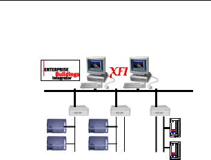
The Building Network Adapter (BNA) delivers exceptional price/performance to meet the requirements of both building owners and service providers. With its combination of scalable performance, density, and low per-port pricing, the Building Network Adapter allows network-layer capabilities to be extended to a much wider range of network configurations and environments.
Customers can now gain the advantages of highperformance network and services, including traffic management to more locations throughout the network.
The Building Network Adapter is using the LANconnection to provide a seamless communication to
EN1B-0198GE51 R0801 |
5 |

BUILDING NETWORK ADAPTER BNA-1C/2CS/2DN
the requesting device. Status information like LAN communication activity, field bus traffic communication and system heartbeat of the Building Network Adapter is indicated by LEDs on the front of the device.
Technically, the Building Network Adapter provides an interface from various Honeywell controller busses that use RS232/RS485 signals to a local area network using 802.3 Ethernet protocol. This allows data to be used by high-level building management systems such as Enterprise Buildings Integrator (EBI), Excel Building Supervisor (XBS), and Excel Facility Integrator (XFI).
This Installation Instruction and User Manual cover all BNA device types listed below.
BNA-1C provides a single RS485 DC coupled C- Bus-compatible communication channel for XL5000 family devices with up to 76.8 kbps.
BNA-2CS provides two RS485 DC coupled C- / S- / FS-90-Bus compatible communication channels for different applications, like Excel IRC and Excel Classic as well as XL5000 family devices with up to 76.8 kbps.
BNA-2DN provides two RS485 AC coupled Manchester encoded L1-Bus (DeltaNet Peer bus) compatible communication channels.
6 |
EN1B-0198GE51 R0801 |

BUILDING NETWORK ADAPTER BNA-1C/2CS/2DN
Additionally, each BNA type is equipped with AUI and RJ45 10Base T connectors plus a RS232 interface.
EN1B-0198GE51 R0801 |
7 |

BUILDING NETWORK ADAPTER BNA-1C/2CS/2DN
2 Location of Parts and Controls
The numbering for the parts and controls in this section is referring to the pictures on the rear side of the title page. In order to have a reference between the numbering here and the device pictures, it is possible to fold this page out.
2.1Front Side
Differences between the various BNA types are explicitly noted in the concerning element description.
1Reset
Hardware reset button. Located directly behind the small hole in the front panel. To reach this button, a pointed object like a sharp pen or an unfolded paper clip is necessary. Pressing this button resets the BNA device immediately. This operation is similar to power on the BNA device.
2Mode
Mode switch button. This button is needed to change the bootloader modes. For a detailed description about BNA operation modes, please refer to chapter 6.2 Operating Modes on Page 25.
3LAN
Local Area Network (LAN) activity display.
8 |
EN1B-0198GE51 R0801 |

BUILDING NETWORK ADAPTER BNA-1C/2CS/2DN
Shows the actual LAN traffic using 4 LEDs.
Col |
Collision indicator |
|
|
(Red) |
|
|
If this LED is on, then two or more |
||||
|
devices on the network are |
||||
|
transmitting at the same time. This is |
||||
|
not a fault, but a normal occurrence |
||||
|
on an Ethernet network. However, |
||||
|
when the Collision LED remains on |
||||
|
for all transmission attempts, it may |
||||
|
indicate an abnormal condition such |
||||
|
as an open end-of-line termination. |
||||
Rx |
Receive indicator |
|
(Green) |
||
|
on means that data is received by the |
||||
|
BNA over the Ethernet. |
|
|
||
Tx |
Transmit indicator |
|
(Green) |
||
|
If this LED is lit up, then the BNA |
||||
|
device sends data to the Ethernet. |
||||
|
When data is transmitted, the Rx |
||||
|
indication |
LED |
is |
lit |
up |
|
simultaneously. |
|
|
|
|
Lnk |
Link indicator |
|
|
(Green) |
|
|
shall always be on when the BNA is |
||||
|
connected via the RJ45 connector to |
||||
|
the Ethernet. If this LED is off under |
||||
|
this circumstance, then it will not be |
||||
|
possible to send or receive any data. |
||||
|
If an AUI transceiver is used to hook |
||||
|
up the BNA to the network, then this |
||||
|
LED will be off in most cases because |
||||
|
|
|
|
|
|
EN1B-0198GE51 R0801 |
|
|
|
|
9 |

BUILDING NETWORK ADAPTER BNA-1C/2CS/2DN
the transceiver shows by itself that it is linked properly to the LAN.
4Ch1
Bus Channel 1 activity display. This display contains two green LEDs, one showing the BNA receive activity (Rx) and the other showing the BNA transmit activity (Tx).
5Ch2
Bus Channel 2 activity display. This display
contains two green LEDs, one showing the BNA receive activity (Rx) and the other showing the BNA transmit activity (Tx).
Note: Ch2 indication is available on two channel devices only. It is not available on a BNA 1C device.
6Heartbeat
System heartbeat display. During BNA system runtime, this LED flashes continuously. This LED is a two-color LED. A red flashing LED means that the BNA bootloader is currently active. A green flashing LED means that an application firmware is running.
7Power
Power indicator. This LED lights up when power is connected to the BNA device.
10 |
EN1B-0198GE51 R0801 |
BUILDING NETWORK ADAPTER BNA-1C/2CS/2DN
2.2Rear Side
Differences between the various BNA types are explicitly noted in the corresponding element description.
8Ch2
3-pin connector for field bus channel 2 connection electrically isolated meets the EMC-and FCC-requirements.
Field Bus wiring is described in chapter 5.2 Field Bus Connection (Ch1 / Ch2) on Page 20.
Note: The Ch2 field bus connector is available on two-channel devices only. It is not available on a BNA 1C device.
9Ch1/Ch2 Bus Termination Switches
These switches are used to select between different field bus terminations. For a detailed description of the different Bus Termination
Switch positions, please refer to chapter
5.3 Bus Termination Switch on Page 20.
Note: The Bus Termination Switch option is available on BNA 1C and BNA 2CS devices only.
The Bus Termination Switch near the Ch2 field bus connector is available on twochannel devices only. It is not available on a BNA 1C device.
EN1B-0198GE51 R0801 |
11 |

BUILDING NETWORK ADAPTER BNA-1C/2CS/2DN
10Ch1
3-pin connector for field bus channel 1 connection electrically isolated meets the EMC-and FCC-requirements. Field Bus wiring is described in chapter 5.2 Field Bus Connection (Ch1 / Ch2) on Page 20.
11AC/DC IN 18-24V
Power connector for 18-24V AC (50...60Hz) or 18-24V DC power supplies.
Power consumption is 5VA (connected via 10BaseT, twisted pair) or 12VA (connected via AUI, 10Base5). An external power supply is required. See also chapter 5.1 Power Connection on Page 19.
12RS232
9-pin SUB-D male RS232 connector, electrically isolated, PC pin compatible, protected against spikes.
This interface is used for initial device set-up and requires a standard Null-Modem cable when interfacing to a PC.
13LAN-AUI
15-pin Attachment Unit Interface female Ethernet LAN connector for coaxial or fiber optic linkage (with AUI transceiver).
1410BaseT
10BaseT RJ-45 Ethernet LAN-connector, meets the requirements of ANSI/TIA/EIA 586 Category 5, for unshielded twisted pair connections.
12 |
EN1B-0198GE51 R0801 |

BUILDING NETWORK ADAPTER BNA-1C/2CS/2DN
3 Before Installation
Please pay attention to the steps listed below prior to installing the Building Network Adapter device.
1Verify that the product has been received without damage.
2Verify that the correct BNA type has been delivered.
3Check package contents. The following items are included in each product package:
Pieces Item
1 Building Network Adapter device
1 |
Building |
Network |
Adapter |
|
Installation |
Instruction |
& User |
|
Manual |
|
|
1 |
Small bag with installation material |
||
The small installation material bag contains the following parts:
Pieces Item
1 2 pole Phoenix power connector
EN1B-0198GE51 R0801 |
13 |

BUILDING NETWORK ADAPTER BNA-1C/2CS/2DN
Pieces Item
23 pole Phoenix controller bus channel connectors
4 Optional wall mounting clips
4 Small inserts
4 Screws
4Please read chapter 5 Connections on page 19 carefully prior to connecting any power and data interface cables to the BNA.
5Please refer to the installation instruction manuals of each component that shall be connected to the BNA, like 95-7545 XLS1000 Installation Instructions, 95-7421 FS90 Installation Instructions, and 95-7551 LAN Installation Instructions, etc.
WARNING:
Do not remove the cover of a BNA device.
There are no user serviceable parts inside.
Any unauthorized modification of this equipment may result in the revocation of the owner’s authority to continue its operation.
14 |
EN1B-0198GE51 R0801 |
BUILDING NETWORK ADAPTER BNA-1C/2CS/2DN
4 BNA Operating Positions
4.1Single Device
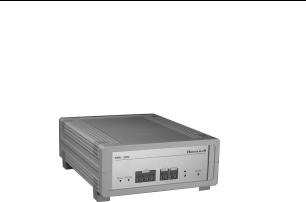
Figure 4-1: Single device operating position
Figure 4-1 shows the normal BNA device operating position e.g. on a desk.
EN1B-0198GE51 R0801 |
15 |
BUILDING NETWORK ADAPTER BNA-1C/2CS/2DN
4.2Stacked Devices
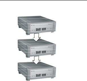
Figure 4-2: Stacked Devices
BNA Devices may also be stacked. Because of stability issues, it is recommended not to stack more than 3 devices.
4.3Wall Mounting
It is also possible to mount the BNA device to a wall. The following sequence describes how the
16 |
EN1B-0198GE51 R0801 |
BUILDING NETWORK ADAPTER BNA-1C/2CS/2DN
device has to be prepared prior to mounting it to a wall.
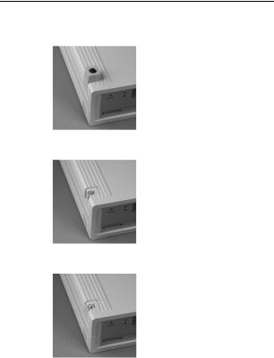
Put the BNA-adapter with the topside down on the desk (Figure 4-3).
Figure 4-3
Remove the four feet (Figure 4-3) from the bottom of the BNA by pushing them horizontally away from the housing with a flat screwdriver (Figure 4-4).
Figure 4-4
Push the four inserts (included) fully and horizontally into the housing (Figure 4-5).
Figure 4-5
EN1B-0198GE51 R0801 |
17 |
 Loading...