


 Loading...
MS3780 Fusion™
Omni/Single Line Scanner
User’s Guide
Disclaimer
Honeywell International Inc. (“HII”) reserves the right to make changes in specifications and other information contained in this document without prior notice, and the reader should in all cases consult HII to determine whether any such changes have been made. The information in this publication does not represent a commitment on the part of HII.
HII shall not be liable for technical or editorial errors or omissions contained herein: nor for incidental or consequential damages resulting from the furnishing, performance, or use of this manual.
This document contains propriety information that is protected by copyright. All rights reserved. No part of this document may be photocopied, reproduced, or translated into another language without the prior written consent of HII.
© 2004 - 2012 Honeywell International Inc. All rights reserved.
Web Address: www.honeywellaidc.com
Trademarks
Metrologic, Quantum, CodeGate, MetroSelect and MetroSet are trademarks or registered trademarks of Metrologic Instruments, Inc. in the United States and/or other countries.
Microsoft, Windows 95, and Windows are registered trademarks of Microsoft Corporation.
IBM is a trademark of International Business Machines Corporation.
Checkpoint is a registered trademark of Checkpoint Systems, Inc.
Other product names mentioned in this manual may be trademarks or registered trademarks of their respective companies and are the property of their respective owners.
Patents
For patent information, please refer to www.honeywellaidc.com/patents.

TABLE OF CONTENTS
Introduction |
|
Product Overview ............................................................................................. |
1 |
Scanner and Accessories................................................................................. |
2 |
Scanner Components....................................................................................... |
4 |
Caution and Serial Number Labels................................................................... |
5 |
Stand Specifications......................................................................................... |
5 |
Cable Removal................................................................................................. |
6 |
Cable Connection Warning............................................................................... |
6 |
Maintenance..................................................................................................... |
6 |
Installation |
|
RS232 or Light Pen .......................................................................................... |
7 |
RS485 or OCIA ................................................................................................ |
8 |
Keyboard Wedge.............................................................................................. |
9 |
Stand-Alone Keyboard Wedge ....................................................................... |
10 |
Full Speed or Low Speed USB (Integrated) ................................................... |
11 |
EAS Deactivation ........................................................................................... |
12 |
Scanner Operation |
|
The Scan Pattern Mode Select Button ........................................................... |
13 |
How to Use CodeGate and the Manual Activation Mode ............................... |
14 |
Indicators |
|
Audible ....................................................................................................... |
15 |
Visual.......................................................................................................... |
16 |
Failure ........................................................................................................ |
17 |
Depth of Field Specifications |
|
Normal Scan Zone ..................................................................................... |
18 |
Reduced Scan Zone................................................................................... |
19 |
Depth of Field by Bar Code Element Width |
|
Normal Scan Zone ..................................................................................... |
20 |
Reduced Scan Zone................................................................................... |
21 |
IR Activation Range........................................................................................ |
22 |
ii |
|

TABLE OF CONTENTS
Troubleshooting Guide ....................................................................................... |
23 |
Design Specifications ......................................................................................... |
27 |
Applications and Protocols ................................................................................. |
29 |
Configuration Modes .......................................................................................... |
30 |
Upgrading the Firmware..................................................................................... |
31 |
Scanner and Cable Terminations ....................................................................... |
32 |
Regulatory Compliance ...................................................................................... |
36 |
Limited Warranty ................................................................................................ |
39 |
Index................................................................................................................... |
41 |
Customer Support .............................................................................................. |
43 |
Technical Assistance...................................................................................... |
43 |
Product Service and Repair............................................................................ |
43 |
iii

INTRODUCTION
The MS3780 Fusion™ is a hand-held, omnidirectional bar code scanner with optional single-line scanning capabilities. It utilizes the powerful Honyewell QuantumE scan engine to provide an outstanding scan performance on all standard 1D bar code symbologies, including GS1 DataBar™ (RSS). Designed for retail applications, the Fusion includes additional key product features like:
•Fully Automatic Scanning Operation
•Single-Line Mode for Menu Reading
•Custom Configurable Scan Pattern
•User-Replaceable Single-Cable Interface to Host (PowerLink Compatible)
•User Configurable Depth of Field
•Easy Bar Code Configuration
•Data Editing
•7 Beeper Tones
•Firmware updates are easily loaded into Flash memory
•OPOS and JPOS System Compatible
•CodeGate™
•Sunrise 2005 Compliant
SCANNER |
INTERFACE |
|
MS3780-9 |
OCIA and RS232 Transmit/Receive |
|
|
|
|
MS3780-11 |
RS485 and Full RS232 |
|
|
|
|
MS3780-38 |
RS232 Low Speed USB*, |
|
Keyboard Emulation Mode or USB Serial Emulation Mode |
||
|
||
|
|
|
MS3780-40 |
Full Speed USB |
|
|
|
|
MS3780-41 |
RS232/Light Pen Emulation |
|
|
|
|
MS3780-47 |
Keyboard Wedge, Stand-Alone Keyboard and |
|
RS232 Transmit/Receive |
||
|
||
|
|
|
MS3780-48 |
Stand Alone Keyboard and RS232 Transmit/Receive |
|
|
|
|
MS3780-120 |
USB and RS232 Transmit/Receive with EAS |
|
|
|
*Configurable for Keyboard Emulation Mode or Serial Emulation Mode. The default setting is Keyboard Emulation Mode.
Applicable for IBM® Host applications.
1

INTRODUCTION
Scanner and Accessories
|
BASIC KIT COMPONENTS |
|
|
||
Part No. |
Description |
|
|
|
|
MS3780 |
Fusion Scanner |
|
|
|
|
00-02269 |
MS3780 User’s Guide * |
|
|
|
|
00-02407 |
MetroSelect™ Configuration Guide * |
|
* Guides also available for download at www.honeywellaidc.com. |
||
|
|
|
|
OPTIONAL ACCESSORIES |
|
Part No. |
Description |
|
|
|
|
AC to DC Power Transformer - Regulated 5.2VDC @ 1A output. |
||
|
|
|
46-00525 |
90VAC – 255VAC United States, Canada and Japan |
|
|
|
|
46-00526 |
90VAC – 255VAC Continental European |
|
|
|
|
46-00527 |
90VAC – 255VAC United Kingdom |
|
|
|
|
46-00528 |
90VAC – 255VAC Australia |
|
|
|
|
46-00529 |
90VAC – 255VAC China |
|
|
|
|
46-00530 |
90VAC – 255VAC India |
|
|
|
|
The following cables are for Fusion models not equipped with EAS. |
||
53-53000x-3 |
RS232 PowerLink Cable with Built in Power Jack |
|
coiled cord, long strain relief, black |
||
|
||
|
|
|
53-53002x-3 |
Keyboard Wedge PowerLink cable with Adapter Cable |
|
coiled cord, long strain relief, black |
||
|
||
|
|
|
53-53020x-3 |
Stand Alone Keyboard PowerLink Cable |
|
coiled cord, long strain relief, black |
||
|
||
|
|
|
MVC-3MPC-IB9 |
Voltage Converter Cable, ±12VDC to +5.2VDC |
|
For IBM Applications |
||
|
||
|
|
|
Other items may be ordered for the specific protocol being used. To order additional items, contact the dealer, distributor or customer service. See page 43 for contact information.
2

INTRODUCTION
Scanner and Accessories
|
OPTIONAL ACCESSORIES |
|
Part No. |
Description |
|
|
|
|
MVC-3MNC-N7052 |
Voltage Converter Cable, ±12VDC to +5.2VDC |
|
For OCIA Applications |
||
|
||
53-53213x-N-3 |
USB Full Speed Cable, Locking Plus-Power™Type A |
|
straight cord, short strain relief |
||
|
||
|
USB Full Speed Cable, Locking Plus-Power™Type A |
|
53-53214x-N-3 |
straight cord, short strain relief |
|
This cable is for use with full speed |
||
|
||
|
USB (-40) interface only. |
|
|
|
|
|
USB Low Speed Communication Cable, |
|
53-53235x-N-3 |
Type A (Non-Locking) Connector |
|
|
straight cord, short strain relief |
|
|
|
|
The following cables are for Fusion models equipped with EAS. |
||
|
RS232 PowerLink Cable with Built in Power Jack and |
|
59-59000x-E-3 |
EAS Connection Wire |
|
|
long strain relief, straight cable, black |
|
|
|
|
|
RS485 PowerLink Cable with Built in Power Jack and |
|
59-59006x-E-3 |
EAS Connection Wire |
|
|
long strain relief, straight cable, black |
|
|
|
|
55-55809x-N-E-3 |
USB, Keyed, Type A, EAS Connection Wire |
|
Long strain relief, straight cable, black |
||
|
||
|
|
|
|
|
|
46-00225 |
Stand |
|
|
|
|
Other items may be ordered for the specific protocol being used. To order additional items, contact the dealer, distributor or customer service. See page 43 for contact information.
Applicable for IBM® Host applications.
3
INTRODUCTION
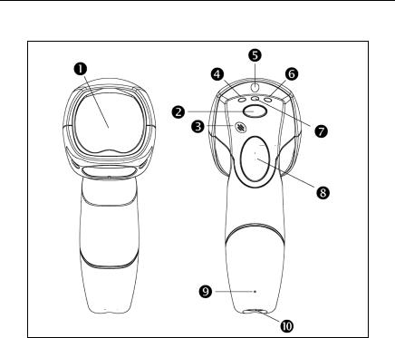
Scanner Components
|
Figure 1. Scanner Components |
|
|
|
|
ITEM NO. |
DESCRIPTION |
|
1 |
Red Output Window, Laser Aperture (See page 36) |
|
|
|
|
2 |
Mode Select Button (See page 13) |
|
|
|
|
3 |
Beeper (See page 15) |
|
|
|
|
4 |
Blue LED, Single-Line Mode / Menu Reading (See page 15) |
|
|
|
|
5 |
White LED (See page 15) |
|
|
|
|
6 |
Blue LED, |
|
All Scan Lines On / Omnidirectional Reading (See page 15) |
||
|
||
|
|
|
7 |
Amber LED, CodeGate (See page 15) |
|
|
|
|
8 |
CodeGate Button (See page 14) |
|
|
|
|
9 |
Pin Hole for Cable Release (See page 6) |
|
|
|
|
10 |
10-Pin RJ45, Female Socket (See page 32) |
|
|
|
4

INTRODUCTION
Caution and Serial Number Labels
Figure 2. Caution and Serial Labels
Caution:
To maintain compliance with applicable standards, all circuits connected to the scanner must meet the requirements for SELV (Safety Extra Low Voltage) according to EN/IEC 60950-1.
To maintain compliance with standard CSA C22.2 No. 60950-1/UL 60950-1 and norm EN/IEC 60950-1, the power source should meet applicable performance requirements for a limited power source.
Stand Specifications
Figure 3. Stand Specifications
5
INTRODUCTION
Maintenance
Smudges and dirt on the unit's window can interfere with the unit's performance. If the window requires cleaning, use only a mild glass cleaner containing no ammonia. When cleaning the window, spray the cleaner onto a lint free, nonabrasive cleaning cloth then gently wipe the window clean.
If the unit's case requires cleaning, use a mild cleaning agent that does not contain strong oxidizing chemicals. Strong cleaning agents may discolor or damage the unit's exterior.
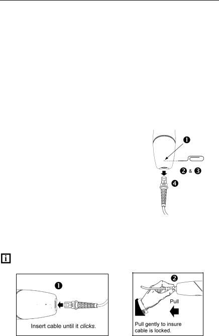
Cable Removal
Disconnect the power supply from the PowerLink cable and turn off power to the host system before removing the cable from the scanner.
1. |
Locate the small ‘pin-hole’ beneath |
|
|
|
the Fusion logo on the front side of |
|
|
|
the scanner near the end of the |
|
|
|
handle. |
|
|
2. |
Bend an ordinary paperclip into the |
|
|
|
shape shown in figure 4. |
|
|
3. |
Insert the paperclip (or other small |
|
|
|
metallic pin) into the small ‘pin-hole’. |
|
|
|
There will be a faint ‘click’ when the |
|
|
|
connector’s lock releases. |
|
|
4. |
Pull gently on the cable’s strain-relief |
|
|
Figure 4. |
|||
|
to remove the cable. |
Cable Connection Warning
Important: If the PowerLink cable is not fully latched the unit can power intermittently.
Figure 5. |
Figure 6. |
6
INSTALLATION
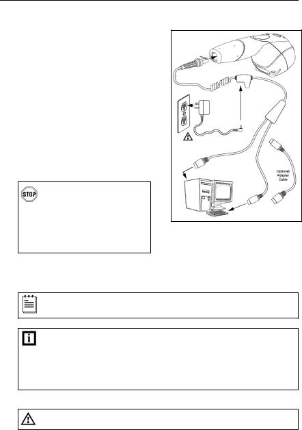
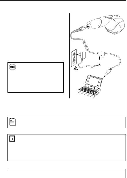
RS232 or Light Pen
1.Turn off the host device.
2.Plug the male 10-pin RJ45 end of the PowerLink cable into the 10-pin socket on the MS3780.
3.Connect the 9-pin female end of the PowerLink cable to the appropriate communication port on the host device
4.Plug the external power supply into the power jack on the PowerLink cable.
Check the AC input requirements of the power supply to make sure the voltage matches the AC outlet. The outlet must be located near the equipment and be easily accessible.
Figure 7.
5. Connect AC power to the transformer.
6. Turn on the host device.
When the scanner first receives power the white LED will flash, one blue LED will turn on and the scanner will emit one beep.
Plugging the scanner into the serial port of the PC does not guarantee that scanned information will appear at the PC. A software driver and correct configuration setting are also required for proper communication to occur.

 See Caution statement on page 5.
7
INSTALLATION
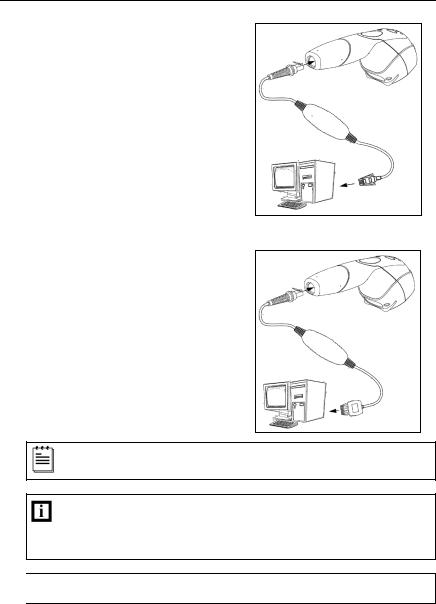
RS485 or OCIA
1.Turn off the host device.
2.Plug the male 10-pin RJ45 end of the MVC cable into the 10-pin socket on the MS3780.
3.For RS485:
Connect the other end of the MVC cable to Port 9 of the host device.
For OCIA:
Connect the other end of the MVC cable to the appropriate
communication port on the host Figure 8. RS485 (above), OCIA (below) device.
4.Turn on the host device.
When the scanner first receives power the white LED will flash, one blue LED will turn on and the scanner will emit one beep.
Plugging the scanner into the serial port of the PC does not guarantee that scanned information will appear at the PC. A software driver and correct configuration setting are also required for proper communication to occur.

 See Caution statement on page 5.
Applicable for IBM® Host applications.
8
INSTALLATION
Keyboard Wedge
1.Turn off the host device.
2.Plug the male 10-pin RJ45 end of the PowerLink cable into the 10-pin socket on the MS3780.
3.Disconnect the keyboard from the host device.
4.Connect the “Y” end of the PowerLink cable to the keyboard and the keyboard port on the host PC. If necessary use the male/female adapter cable supplied with the scanner for proper connections.
5.Plug the external power supply into the power jack on the PowerLink cable.
Check the AC input requirements of the power supply to make sure the voltage matches the AC
outlet. The outlet must be
located near the equipment Figure 9. and be easily accessible.
6.Connect AC power to the transformer.
7.Turn on the host device.
When the scanner first receives power the white LED will flash, one blue LED will turn on and the scanner will emit one beep.
Powering the MS3780 directly from the host device can sometimes cause interference with the operation of the scanner or the computer. Not all computers supply the same current through the keyboard port. For this reason, Honeywell recommends using an external power supply. For additional information contact a customer service representative.
See Caution statement on page 5.
9
INSTALLATION
Stand-Alone Keyboard
1.Turn off the host device.
2.Plug the male 10-pin RJ45 end of the PowerLink cable into the 10-pin socket on the MS3780.
3.Connect the other end of the PowerLink cable to the keyboard port on the host device.
4.Plug the external power supply into the power jack on the PowerLink cable.
Check the AC input |
|
requirements of the power |
|
supply to make sure the |
|
voltage matches the AC |
|
outlet. The outlet must be |
|
located near the equipment |
|
and be easily accessible. |
|
5. Connect AC power to the |
Figure 10. |
transformer. |
|
6. Turn on the host device. |
|
When the scanner first receives power the white LED will flash, one blue LED will turn on and the scanner will emit one beep.
Powering the MS3780 directly from the host device can sometimes cause interference with the operation of the scanner or the computer. Not all computers supply the same current through the keyboard port. For this reason, Honeywell recommends using an external power supply. For additional information contact a customer service representative.

 See Caution statement on page 5.
10
INSTALLATION
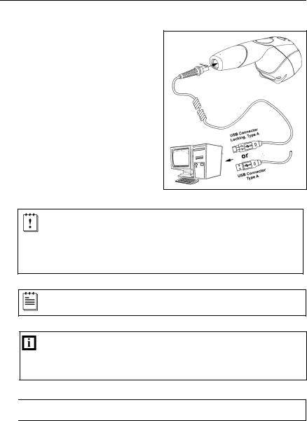
Full Speed or Low Speed USB (Integrated)
1.Turn off the host device.
2.Plug the male 10-pin RJ45 end of the USB PowerLink cable into the 10-pin socket on the MS3780.
3.Plug the other end of the USB interface cable into the host device’s USB port.
4.Turn on the host device.
Figure 11.
As a default, the MS3780-38 leaves the factory with USB Keyboard Emulation Mode enabled.
For information on configuring the MS3780-38 for USB Serial Emulation Mode, please refer to the USB: Low Speed section of the MetroSelect Configuration Guide (PN 00-02407).
When the scanner first receives power the white LED will flash, one blue LED will turn on and the scanner will emit one beep.
Plugging the scanner into the USB port of the PC does not guarantee that scanned information will appear at the PC. A software driver and correct configuration setting are also required for proper communication to occur.

 See Caution statement on page 5.
11
INSTALLATION
EAS Deactivation
SW1 and SW2 are the switch banks inside the Checkpoint Device that set the deactivation range. The following is a list of Checkpoint recommended switch bank settings.
Checkpoint Recommended Switch Bank Settings
For RS232 and IBM
SW1 |
|
SW2 |
|
Switch 1 and 6 |
ON |
Switch 1 and 6 |
ON |
Switch 2, 3, 4, and 5 |
OFF |
Switch 2, 3, 4, and 5 |
OFF |
Checkpoint Recommended Switch Bank Settings
For USB
SW1 |
|
SW2 |
|
Switch 1 |
ON |
Switch 1 |
ON |
Switch 2, 3, 4, 5, and 6 |
OFF |
Switch 2, 3, 4, 5, and 6 |
OFF |
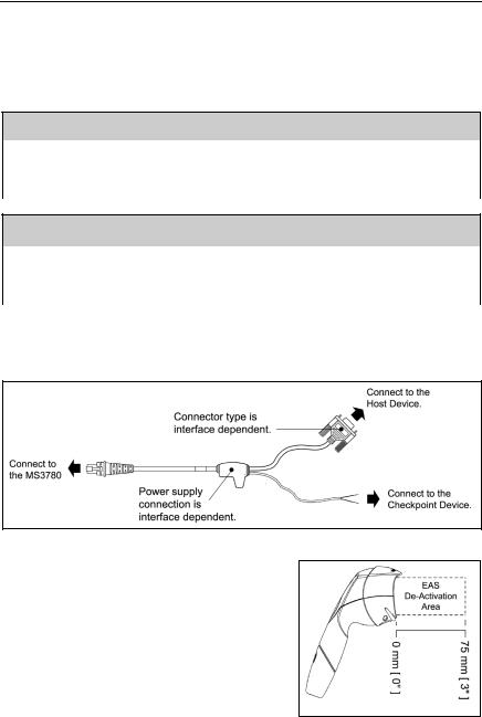
All Fusion models equipped with EAS capabilities have an EAS designation in their model numbers. The cable supplied with these units will have additional wires for connection to the Checkpoint Device.
Figure 12. EAS Cable
Figure 13 shows the location of the EAS deactivation area for Fusion.
It is important to pass the entire tag through this area to deactivate the security tag.
Figure 13. EAS Deactivation Area
12
Loading...