


 Loading...
MS2420 / MS2430
Bar Code Scanner / Diva Scale
Installation and User’s Guide

Disclaimer
Honeywell International Inc. (“HII”) reserves the right to make changes in specifications and other information contained in this document without prior notice, and the reader should in all cases consult HII to determine whether any such changes have been made. The information in this publication does not represent a commitment on the part of HII.
HII shall not be liable for technical or editorial errors or omissions contained herein: nor for incidental or consequential damages resulting from the furnishing, performance, or use of this manual.
This document contains propriety information that is protected by copyright. All rights reserved. No part of this document may be photocopied, reproduced, or translated into another language without the prior written consent of HII.
© 2006 - 2012 Honeywell International Inc. All rights reserved. Web Address: www.honeywellaidc.com
Trademarks
Stratos, MetroSet, and MetroSelect are a trademarks or registered trademarks of Metrologic Instruments, Inc. in the United States and/or other countries.
Microsoft, Windows, and Windows 95 are trademarks or registered trademarks of Microsoft Corporation. IBM is a trademark of International Business Machines Corporation.
Other product names mentioned in this manual may be trademarks or registered trademarks of their respective companies and are the property of their respective owners.
Patents
For patent information, please refer to www.honeywellaidc.com/Patents.

Table of Contents |
|
Introduction |
|
Manual Scope.............................................................................................................................................. |
1 |
Product Overview ........................................................................................................................................ |
1 |
Base Kit Components .................................................................................................................................. |
2 |
Optional Accessories ................................................................................................................................... |
2 |
Replacement Parts ...................................................................................................................................... |
5 |
General Precautions .................................................................................................................................... |
6 |
Design Specifications |
|
Operational .................................................................................................................................................. |
7 |
Mechanical .................................................................................................................................................. |
7 |
Electrical...................................................................................................................................................... |
8 |
Scale Capacities .......................................................................................................................................... |
8 |
Environmental.............................................................................................................................................. |
8 |
Base Model Characteristics |
|
MS2420/MS2430 Scanner/Diva Scale Components .................................................................................... |
9 |
MS2420 Dimensions.................................................................................................................................. |
11 |
MS2430 Dimensions.................................................................................................................................. |
11 |
Connector Panel........................................................................................................................................ |
12 |
Caution and Serial Number Labels ............................................................................................................ |
13 |
Installation |
|
Quick Installation Outline ........................................................................................................................... |
15 |
Site Requirements ..................................................................................................................................... |
15 |
Vertical Clearance ........................................................................................................................... |
15 |
Ventilation and Spacing................................................................................................................... |
15 |
Service Access................................................................................................................................ |
16 |
Power Installation ............................................................................................................................ |
16 |
Checkout Counter Layout Consideration ......................................................................................... |
16 |
Unpacking the Unit .................................................................................................................................... |
17 |
MS2420/MS2430 Package Warning................................................................................................ |
18 |
Installing the Unit in the Counter ................................................................................................................ |
18 |
Lifting the Unit by the Finger Recesses ........................................................................................... |
18 |
MS2420 Mounting Diagram............................................................................................................. |
19 |
MS2430 Mounting Diagram (Two Point Support)............................................................................. |
20 |
MS2430 Mounting Diagram (Three Point Support) .......................................................................... |
21 |
Cable Installation (Interface Specific)......................................................................................................... |
22 |
RS232 ............................................................................................................................................. |
22 |
Full Speed USB............................................................................................................................... |
24 |
IBM OEM.................................................................................................................................. |
25 |
Serial Emulation Mode ............................................................................................................. |
25 |
Keyboard Emulation Mode ....................................................................................................... |
25 |
RS485 ............................................................................................................................................. |
27 |
Cable Installation (Secondary Honeywell Scanner).................................................................................... |
29 |
EAS Deactivation....................................................................................................................................... |
31 |
iii

Scanner Operation |
|
Scan Zone ................................................................................................................................................. |
33 |
Wake Activation Area (Photocell LED Output) ........................................................................................... |
35 |
Changing the Wake Area Sensitivity Level ...................................................................................... |
36 |
Audible Indicators ...................................................................................................................................... |
37 |
Visual Indicators ........................................................................................................................................ |
38 |
Failure Modes............................................................................................................................................ |
39 |
Diagnostic Indicator Display; Error Codes.................................................................................................. |
40 |
Power Save Modes.................................................................................................................................... |
43 |
Beeper Options and Button Functions ....................................................................................................... |
44 |
Beeper Tone and Volume Control ................................................................................................... |
44 |
The Multi-Function Button ............................................................................................................... |
44 |
Startup....................................................................................................................................................... |
45 |
Power-Up Test Mode................................................................................................................................. |
45 |
Configuration Mode ................................................................................................................................... |
45 |
Scale Operation |
|
Scale Zeroing ............................................................................................................................................ |
47 |
Calibration ................................................................................................................................................. |
48 |
Tools Required................................................................................................................................ |
48 |
Scale Calibration Methods............................................................................................................... |
48 |
Priming the Scale for Calibration (lbs. & kg) .................................................................................... |
49 |
Scale Calibration Procedure (lbs. & kg) with Remote Display .......................................................... |
50 |
Bar Code Calibration Procedure without Remote Display................................................................ |
53 |
Calibration Verification............................................................................................................................... |
58 |
U.S. Pounds (lbs.) ........................................................................................................................... |
58 |
Kilograms (kg) ................................................................................................................................. |
59 |
Security Seal Installation............................................................................................................................ |
60 |
Pressure Sensitive Security Seal..................................................................................................... |
60 |
Wire Security Seal (Conversion Kit 46-00359)................................................................................. |
61 |
Maintenance |
|
Horizontal Scan Window Replacement ...................................................................................................... |
63 |
Daily Maintenance ..................................................................................................................................... |
64 |
Troubleshooting |
|
Troubleshooting Symptom / Solution Chart................................................................................................ |
65 |
Scanner and Cable Terminations |
|
Scanner Pinout Connections...................................................................................................................... |
69 |
Cable Connector Configurations ................................................................................................................ |
71 |
Regulatory Compliance |
|
Safety ........................................................................................................................................................ |
73 |
EMC .......................................................................................................................................................... |
74 |
Weights & Measures.................................................................................................................................. |
75 |
Limited Warranty ........................................................................................................................................... |
77 |
Index............................................................................................................................................................... |
79 |
Customer Support ......................................................................................................................................... |
81 |
Technical Assistance ................................................................................................................................. |
81 |
Product Service and Repair ....................................................................................................................... |
81 |
iv |
|

 Introduction
Manual Scope
This guide provides information on the installation, setup, and operation of Honeywell’s MS2420 and MS2430 scanner/Diva scale unit. It is designed to be used in conjunction with MetroSelect™ Configuration Guide
(PN 00-02407x) and the MS2x20 Stratos™ Series Scanner/Diva Scale Configuration Addendum (PN 00-02272x).
Product manuals are also available for download in Adobe® Acrobat® file format at www.honeywellaidc.com.
Product Overview
MS2420 and MS2430 scanner is designed to meet the demanding needs of high volume supermarket and point-of-sale applications. With advanced features like 5-sided, 360° scanning, 5400 scans per second, a comprehensive scan zone and advanced decoding software, this high performance series of in-counter scanner/Diva scale products guarantees fast customer checkouts with minimal operator fatigue and stress. The MS2420 and MS2430 scanner is equipped with a multitude of standard features including:
StratosSCAN – 5-sided, 360° scanning that minimizes product orientation
StratosSPHERE – Decoding software that reads poor quality and damaged bar codes
StratosSYNC – Horizontal and vertical scanning zones operate independently from one another
GS1 DataBar Decoding – Decodes GS1 DataBar, GS1 DataBar Limited, and GS1 DataBar Expanded symbologies
Flash ROM – Upgrade latest software enhancements on site
Powered Aux Port – Connect hand-held scanner for large or bulky items
Integrated Scale – Factory integrated Mettler Toledo Diva scale
Loud Speaker – 3 volume/7 tone settings can be heard in all environments
Easy Configuration – Windows® based utility or simple bar code setup
Fully Automatic – “No touch” wake up from power save modes
EAS Deactivation – Electronic Article Surveillance (EAS) equipped (EAS cable is an optional purchase)
Field Replaceable Vertical Window – Quickly remove vertical window for cleaning or replacement
StratosSCOPE – Visual diagnostic indicator for easy to read feedback on scanner condition
StratosSWAP – Modular optics engine technology – small, pre-aligned, field replaceable modules
StratosSCHOOL – Operator training software
1

Base Kit Components
Part # |
|
|
Description |
MS24x0-105Kz |
Scanner/Diva Scale |
||
|
|
|
|
|
x |
2 |
MS2420; 399 mm (15.7") |
|
|
|
|
|
3 |
MS2430; 508 mm (20.0") |
|
|
|
||
|
|
|
|
|
z |
D |
Diamonex Horizontal Window |
|
|
|
|
|
S |
Sapphire Horizontal Window |
|
|
|
||
|
|
|
|
00-02407* |
MetroSelect Configuration Guide |
||
|
|
||
00-02272* |
MS2x20 Stratos Series Scanner/Diva Scale Configuration Addendum |
||
|
|
||
00-05310* |
MS2420/MS2430 Scanner/Diva Scale Installation and User’s Guide |
||
|
|
|
|
* Guides also available for download at www.honeywellaidc.com.
Other items may be ordered for the specific protocol being used. To order additional items, contact the dealer, distributor or call the customer service department.
Optional Accessories
Part # |
Description |
|
57-57210-N-3 |
RS232 Interface Cable, Straight Cord with Short Strain Relief |
|
|
|
|
57-57212-N-3 |
RS485 Port 9 Cable, Straight Cord |
|
|
|
|
57-57201-N-3 |
USB Full Speed Communication Cable, Straight Cord, Type A (Non-Locking) |
|
Connector |
||
|
||
|
|
|
57-57227-N-3 |
USB Full Speed Communication Cable, Straight Cord, |
|
Locking 12V Plus-Power™ Type A |
||
|
||
|
|
|
57-57000-N-3 |
Dual Interface Cable, Straight Cord with Short Strain Relief |
|
|
|
|
57-57008-N-3 |
Aux Program Cable, Straight Cord with Short Strain Relief |
|
|
|
|
57-57099-3 |
LSO RS232 PowerLink AUX Cable w/ power jack Straight Cord with Short Strain Relief |
|
|
|
|
57-57099-3-12 |
RS232 AUX, Straight Cord, 3.7 m (12') (for 95xx, 5145 and 7580 scanners) |
|
|
|
|
CBL-420-300-C00 |
RS232 AUX, Coiled Cord (for 1200, 1300 and 1900 Series scanners) |
|
|
|
|
52-52511 |
EAS cable, 24" |
|
|
|
|
52-52556 |
EAS cable, 6' |
|
|
|
Applicable for IBM® Host applications.
2

Optional Accessories
Part # |
|
|
|
|
Description |
|
|
|
AC to DC Power Transformer - Regulated |
||
|
|
Output: |
+5.2V @ 4A |
+12V @ 1.5A |
|
70-74868 |
120V |
United States and Canada |
|
||
70-74882 |
220V |
– 240V Continental European |
|
||
70-74880 |
220V |
– 240V |
United Kingdom |
|
|
70-74884 |
220V |
– 240V |
China |
|
|
70-74886 |
220V |
– 240V |
Australia |
|
|
70-74888 |
220V |
– 240V India |
|
|
|
3
Optional Accessories
Part # |
Description |
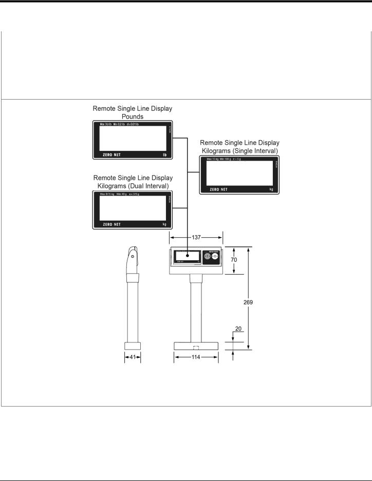
46-00375 |
Remote Single Line Scale Display (lb.) (See Figure 1) |
46-00376 |
Remote Single Line Scale Display (kg.) Dual Interval (See Figure 1) |
46-01075 |
Remote Single Line Scale Display (kg.) Single Interval (See Figure 1) |
Other Four Line Scale Display currency lens overlay stickers are available. To order additional items or replacement parts, contact the dealer, distributor or call the customer service department.
Figure 1
* All dimensions are shown in mm (millimeters).
Specifications are subject to change without notice.
4

Replacement Parts
Part # |
Description |
|
Window types (Diamonex and Sapphire) are not interchangeable due to laser safety |
|
and/or scanner performance differences. |
Caution |
To change window type, the scanner must be returned to the manufacturer for |
|
reconfiguration. |
|
|
46-00296 |
Diamonex Platter – Full Size with Product Weight Roll Bar / Platter Lift Handle |
|
|
46-00297 |
Sapphire Platter – Full Size with Product Weight Roll Bar / Platter Lift Handle |
|
|
46-01084 |
Sapphire Platter – 508 mm with Product Weight Roll Bar / Platter Lift Handle |
|
|
46-01085 |
Diamonex Platter – 508 mm with Product Weight Roll Bar / Platter Lift Handle |
|
|
Other items may be ordered for the specific protocol being used. To order additional items, contact the dealer, distributor or call the customer service department.
5
General Precautions
The following are some general precautions to remember when handling your MS2420/MS2430 series scanner.
Do not turn the unit upside down with the platter in place.
Do not press on the window in the replacement platter or the vertical window frame.
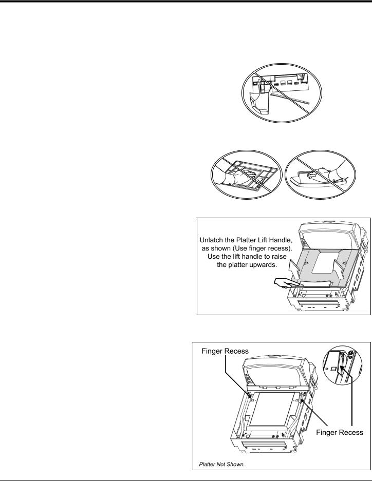
Platter Removal
No hardware or tools are required to remove the platter (see Figure 4). Refer to the Maintenance section of this manual for additional information on platter replacement.
Note: See caution statement on page 5.
Finger Recesses
Rest both thumbs against the vertical window frame for added stability when lifting the unit by the finger recesses.
Figure 2
Figure 3
Figure 4
Figure 5
6
 Design Specifications
Operational
Light Source: |
VLD 650 nm |
|
|
|
|
|
|
|
|
Peak Laser Power: |
<1.5 mW |
|
|
|
|
|
|
|
|
Embedded Laser: |
Max Optical Power: |
10 mW |
|
|
|
|
|
|
|
Wavelength: |
650 nm |
|
||
|
|
|||
|
|
|
|
|
Horizontal Depth of Field: |
0 mm – 100 mm (0"- 4") for 0.33 mm (13 mil) Bar Code |
|||
|
|
|
|
|
Vertical Depth of Field: |
0 mm - 216 mm (0"- 8.5") for 0.33 mm (13 mil) Bar Code |
|||
|
|
|
|
|
Scan: |
(Scan) Speed: 5400 Scan Lines per Second |
(Scan) Zone: 360° |
||
|
|
|
|
|
No. of Scan Lines: |
54 (38 Horizontal / 16 Vertical) |
|
||
|
|
|
|
|
Motor Speed: |
6000 / 6000 RPM (Horizontal / Vertical ) |
|
||
|
|
|
|
|
Min Bar Width: |
0.114 mm (4.5 mil) |
|
|
|
|
|
|
||
Decode Capability: |
All Standard 1-D Bar Codes, GS1 DataBar, GS1 DataBar Expanded, and |
|||
GS1 DataBar Limited Bar Codes |
|
|||
|
|
|
|
|
System Interfaces: |
RS232, Aux RS232, RS485, and USB |
|
||
|
|
|
|
|
Print Contrast: |
35% Minimum Reflectance Difference |
|
||
|
|
|
||
No. Characters Read: |
Up to 80 data characters. Maximum number will vary based on symbology |
|||
and density. |
|
|
|
|
|
|
|
|
|
Beeper Operation: |
7 Tones or No Beep; 3 Volume Settings |
|
||
|
|
|
|
|
|
Blue |
|
Blue Flash |
Amber |
Indicators (LED): |
|
|
|
|
Laser ON, Ready to |
|
Good Read, Decoding |
Scale at Zero |
|
|
|
|||
|
Scan |
|
||
|
|
|
|
|
|
|
|
|
|
Mechanical
MS2420 L x W x H: |
399 mm (15.7") [L] |
292 mm (11.5") [W] |
130 mm (5.12") [Tower Height] |
|
|
|
|
|
|
MS2430 L x W x H: |
508 mm (20.0") [L] |
292 mm (11.5") [W] |
130 mm (5.12") [Tower Height] |
|
|
|
|
|
|
Depth (Below Counter): |
100 mm (3.9") |
|
|
|
|
|
|
|
|
Weight (with Platter): |
MS2420: |
9.97 kg (22 lbs.) |
|
|
|
|
|
|
|
MS2430: |
10.8 kg (24 lbs.) |
|
||
|
|
|||
|
|
|
|
|
Specifications are subject to change without notice.
7

Electrical
Voltage Supply: |
4A @ +5V / 1.5A @ +12V |
|||
|
|
|
||
Power: |
Operating: |
11.9 Watts |
||
|
|
|
||
Standby: |
3.25 Watts |
|||
|
||||
|
|
|
|
|
Current: |
Operating: |
1.7A |
@ 5.2V / 0.2A @ 12V |
|
|
|
|
||
Standby: |
0.6A |
@ 5.2V / 0.07A @ 12V |
||
|
||||
|
|
|
||
DC Transformers: |
Class I; 5.2VDC @ 4A; 12VDC @ 1.5A |
|||
|
|
|||
For Regulatory Compliance Information, refer to pages 73 - 75. |
||||
|
|
|
|
|
Scale Capacities
Capacity: |
kg unit |
6.0 / 15.0 kg |
lb. unit |
15.0 / 30.0 lb. |
|
|
|
|
|
Minimum Increments: |
kg unit |
0.002 / 0.005 kg |
lb. unit |
0.005 / 0.01 lb. |
|
|
|
|
|
Maximum Static Weight: |
kg unit |
75.0 kg |
lb. unit |
150.0 lb. |
|
|
|
|
|
Adjustments required: |
Calibration only. |
|
|
|
|
|
|
|
|
Environmental
Operating Temperature: |
0°C to 40°C (32°F to 104°F) |
|
|
IP Rating: |
IP 55 |
|
|
Light Levels: |
4842 Lux (450 foot-candles) |
|
|
Storage Temperature: |
-40°C to 60°C (-40°F to 140°F) |
|
|
Humidity: |
5% to 95% Relative Humidity, Non-Condensing |
|
|
Contaminants: |
Sealed to resist airborne particulate contaminants. |
|
|
Ventilation: |
None Required |
|
|
Specifications are subject to change without notice.
8

 Base Model Characteristics
MS2420/MS2430 Scanner / Mettler-Toledo DIVA Scale Components*
Figure 6. Components*
*MS2420 shown
9

MS2420/MS2430 Scanner / Mettler-Toledo DIVA Scale Components
Item No. |
Description of Item in Figure 7 |
|
1 |
Scale Zero Button (see page 47) |
|
|
|
|
2 |
Amber LED, Scale Zero Indicator (see page 47) |
|
|
|
|
3 |
Volume/Tone Multi-Function Button (see page 44) |
|
|
|
|
4 |
Blue LED Indicators (see page 38) |
|
|
|
|
5 |
Photocell Window |
|
|
|
|
6 |
Speaker |
|
|
|
|
7 |
Finger Recesses for Lifting (Located Under Platter) |
|
|
|
|
8 |
Replaceable Stainless Steel Platter with Diamonex or Sapphire Horizontal Window |
|
(Laser Aperture) |
||
|
||
|
|
|
9 |
Flow Direction Indicator |
|
|
|
|
|
Sealed Calibration Switch/Button Cover (Located Under Platter) |
|
10 |
On a fully installed unit the calibration switch cover should be sealed with a lead wire or paper |
|
seal. This seal indicates the appropriate Federal, State, and Local Weights and Measures |
||
|
||
|
authorities have calibrated the scale. See the Scale Operation: Calibration section of this |
|
|
guide for further information. |
|
|
|
|
11 |
Produce Weigh Flip Up Bar |
|
|
|
|
12 |
Leveling Bubble for Scale Arms |
|
|
|
|
13 |
Diagnostic Indicator Display (see page 40 for Error Codes) |
|
|
|
|
14 |
Interface, Aux Scanner and EAS Connectors ( see page 12 ) |
|
|
|
|
15 |
Power and Scale Connectors ( see page 12 ) |
|
|
|
|
16 |
Leveling Feet |
|
|
|
Note: Scanner/Diva Scale label information can be found on page 13.
10
MS2420/MS2430 Scanner / Mettler-Toledo DIVA Scale
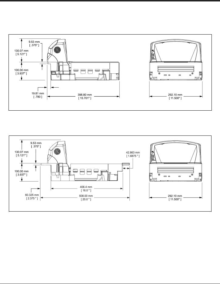
MS2420 Dimensions
Figure 7. MS2420 Dimensions
MS2430 Dimensions
Figure 8. MS2430 Dimensions
Specifications are subject to change without notice.
11
MS2420/MS2430 Scanner / Mettler-Toledo DIVA Scale
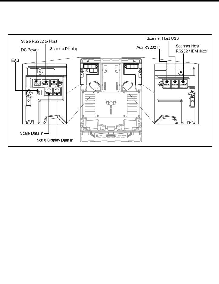
Connector Panel
Figure 9. MS2420/MS2430 Connector Panel
12

MS2420/MS2430 Scanner/Diva Scale
Caution and Serial Number Labels
Figure 10. MS2420/MS2430 Label Locations (Top) and Examples (Bottom)
Caution: To maintain compliance with applicable standards, all circuits connected to the imager must meet the requirements for SELV (Safety Extra Low Voltage) according to EN/IEC 60950-1.
To maintain compliance with standard CSA C22.2 No. 60950-1/UL 60950-1 and norm EN/IEC 60950-1, the power source should meet applicable performance requirements for a limited power source.
13

14

 Installation
Quick Installation Outline
The following is a quick preview of the steps required for first time installations. Each item is discussed in detail later in this section.
Determine clearance, ventilation and service access requirements.
Determine checkout counter layout taking into account package flow, cable routing, and power requirements.
Choose the mounting option which provides the best cable/power access and unit stability.
Unpack the unit.
Make the appropriate countertop cutouts and install all support brackets.
Place the unit in the counter.
Install the platter.
Follow the steps under the correct interface to connect the cables and power supply.
Configure the unit for the correct interface.
Calibrate the Diva scale.
Site Requirements
Before installing your MS2420/MS2430 scanner/Diva scale, please consider the following items.
Vertical Clearance
A minimum clearance height of 5.25" from the checkout counter surface is needed for the vertical 'hood' on all of the scanner models.
Ventilation and Spacing
All MS2420 and MS2430 models have a die-cast housing to dissipate heat allowing the unit to operate without a ventilation fan. The temperature surrounding the unit is recommended not to exceed 40°C (104°F). There should be adequate convection and minimal heat producing equipment in close proximity of the unit.
A cooling fan with a filter is recommended if there will be a conveyor motor or other heat producing equipment close to the unit that will create a high temperature environment.
Adequate spacing between the unit and the checkout counter opening is required for proper operation of the scale. When the scanner/Diva scale model is mounted properly, the scale platter should be able to move up and down freely without hitting the edges of the checkout counter cutout. Refer to Installing the Unit in the Counter beginning on page 18 of this guide for detailed cutout dimensions and mounting instructions.
15

Site Requirements
Service Access
When routing and installing the cable(s) and power supply, make sure you leave access that these components may be swapped easily without the need to remove the unit from the checkout counter.
When changing the StratosSWAP optics engine modules, removing the unit completely from the checkout counter is recommended.
When calibrating or zeroing the scale, do not remove the unit from the checkout counter. Refer to the Scale Operation Section beginning on page 47 of this guide for detailed instructions on zeroing and calibration.
Power Installation
The Power Supply (AC/DC) should be connected to an AC Outlet that is free of electrical noise (clean). A qualified electrician can determine the amount of electrical noise on the AC line. See additional information on power installation and restrictions under the Installation: Interface section of this manual.
Note: A switched AC outlet is recommended. The switch should be located on the operator’s side of the checkout counter in close proximity to the MS2420/MS2430 to facilitate calibration and service of the unit.
Checkout Counter Layout Considerations
When placing a scanner in a checkout counter, the following factors should be considered.
Items should flow at a distance to the operator that maximizes comfort. The operator should not need to stretch or strain to reach for and scan packages.
The MS2420 and MS2430 can scan a bar code on five sides of a package. The packages should flow into the scan area that provides the maximum reading performance. No lifting or orientation of the items is necessary. A properly placed item diverter can maximize the flow of packages.
In what direction are the packages flowing? Most checkout counters are designed for left-handed takeaway. If the operator is facing the vertical window of the scanner, packages flow from the operator's right to left. The packages are in queue on the conveyor to the right and the bagging is to the left.
16
Unpacking the Unit
1.Make sure the shipping box is topside up before opening.
2.Remove the accessories box and check the box’s content for the following items.
Product Manuals
Power Supply
Communication Cables
Remote Scale Display (Optional)
3.Carefully remove the platter and store it in a safe location until the unit is properly installed into the checkout counter.
4.Lift the MS2420/MS2430 scanner out of the box by carefully grasping both sides near the center of the unit and lifting directly up. Refer to Figure 12 for hand placement.
Important! Do not remove the MS2420/MS2430 scanner from the box by grabbing the shipping foam. This can result in the unit falling!
5.Carefully remove the shipping foam from around the MS2420/MS2430 scanner.
Figure 11
Figure 12
Figure 13
17
Unpacking the Unit
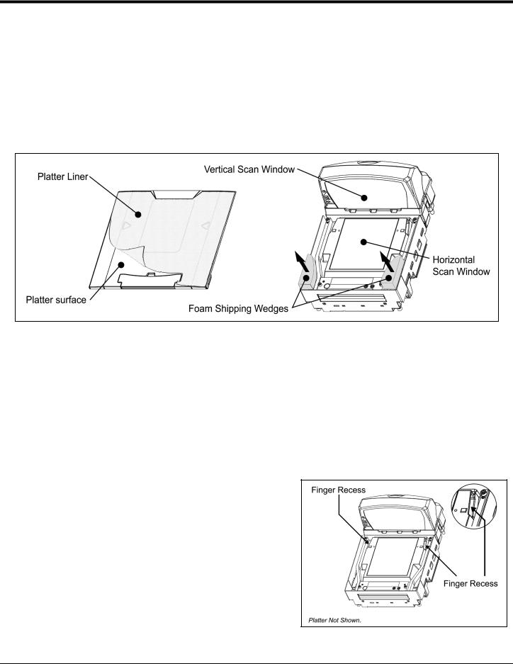
MS2420/MS2430 Package Warning
There is a protective film located on the topside platter surface, vertical scan windows outer surface, and the horizontal scan windows top surface. These protective films must be removed prior to performing any scanner operation (see Figure 14).
Both foam wedges securing the scale arms during shipping must be removed or the scale will not function (see Figure 14)!
Figure 14. Protective shipping foam and lining.
Note: Do not discard these instructions and shipping foam wedges! If the unit is going to be reshipped at any time this foam must be reinstalled prevent damage to the scale arms during shipping.
Installing the Unit in the Counter
Before starting to mount the MS2420/MS2430 determine:
the scanner's orientation in reference to the operator and the direction of package flow,
the mounting method that provides the most stability for the scanner, and
if any additional materials or tools are required for installation.
Lifting the Unit by the Finger Recesses
There are two finger recesses located under the removable platter near the base of the vertical window. These finger recesses are provided to assist in installation when placing the unit in the checkout counter cutout (see Figure 15).
To decrease the risk of dropping the unit during installation, rest both thumbs against the vertical window frame for added stability when lifting the unit by the finger recesses. The unit may tilt forward when lifted by the finger recesses if it is not stabilized making installation in
the countertop cutout difficult. Figure 15. Lifting the Unit by the Finger
Recesses
18
Installing the Unit in the Counter
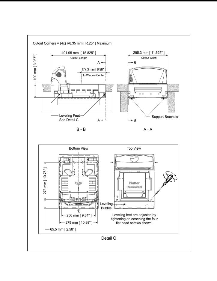
MS2420 Mounting Diagram
Figure 16. MS2420 Mounting Diagram
Specifications are subject to change without notice.
19
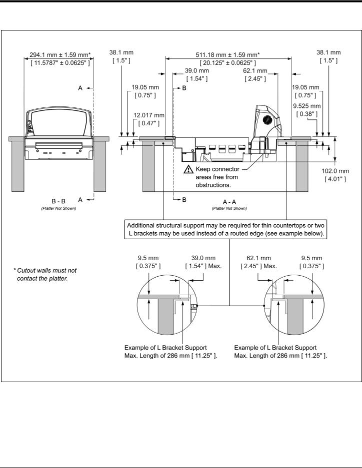
MS2430 Mounting Diagram (Two Point Support)
Figure 17. MS2430 Mounting Diagram, Two Point Support
Specifications are subject to change without notice.
20
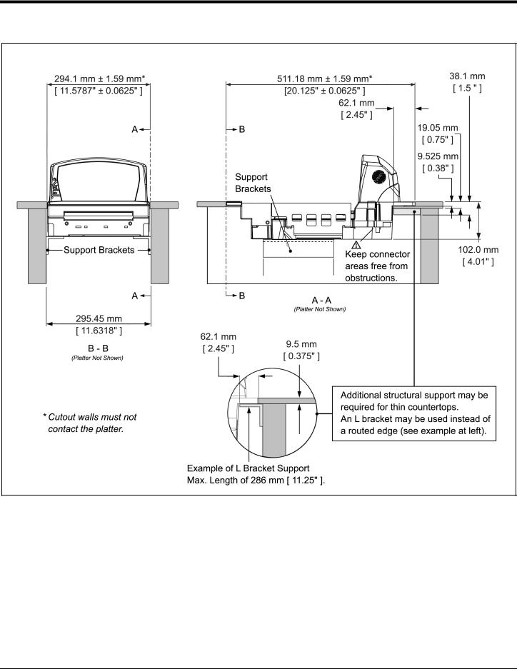
MS2430 Mounting Diagram (Three Point Support)
Figure 18. MS2430 Mounting Diagram, Three Point Support
Specifications are subject to change without notice.
21

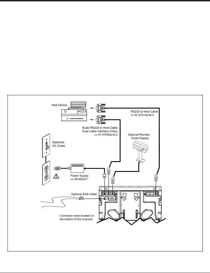
Cable Installation (Interface Specific)
RS232
The following steps describe how to properly install the cables for an RS232 application. The scanner/Diva scale must then be configured to match the host’s RS232 parameters. Cable installation alone does not guarantee that the scanner will communicate properly with the host system.
Note: Configuration bar codes are located in the MetroSelect Configuration Guide (PN 00-02407x) and the MS2x20 Stratos Series Scanner/Diva Scale Configuration Addendum (PN 00-02272x).
1.Turn off the host system.
2.Plug the 10-pin RJ45 end of the RS232 interface cable (PN 57-57210x-N-3) into the 10-pin socket labeled ‘Scanner Host RS232’ on the bottom of the scanner. Refer to the figure on page 23.
3.Connect the other end of the RS232 cable to the proper communication port on the host device.
Stop: Before continuing, verify that the RS232 interface cable is connected to the appropriate interface socket on the scanner. An incorrect cable connection can cause communication problems or potential damage to the scanner and/or terminal.
Steps 4 and 5 are for dual cable interfaces where the scale and the scanner connect to the host with their own separate communication cables. Skip to step 6 for a single cable interface where the scale and scanner connect to the host with a single cable.
4.Plug the dual interface cable (PN 57-57000x-N-3) into the 10-pin socket labeled ‘Scale RS232 to Host’ on the bottom of the scanner.
5.Connect the other end of the dual interface cable (PN 57-57000x-N-3) to the appropriate communication port on the host’s scale device.
6.Plug the optional remote scale display cable (PN 46-00375, 46-00376, or 46-00377) into the 10-pin socket labeled ‘Scale to Display’ on the bottom of the scanner.
7.Plug the external power supply (PN 46-002xx) into the 3-pin Molex socket labeled ‘DC Power In’ on the bottom of the scanner.
Note: Check the AC input requirements of the power supply to make sure the voltage matches the AC outlet. The outlet should be located near the equipment and be easily accessible.
Using a switched AC outlet is recommended. The switch should be located on the operator’s side of the checkout counter in close proximity to the scanner to facilitate calibration and service of the unit.
8. Connect AC power to the transformer. If the AC outlet is equipped with an on/off switch, turn the power on.
22
Cable Installation (Interface Specific)
RS232
9.Turn on the host system.
10.Scan the Recall Defaults bar code.
Note: The Recall Defaults bar code is located in the MetroSelect Configuration Guide, under Need to Start Over (PN 00-02407x).
11. Configure the scanner to match the host system’s RS232 parameters.
Note: Refer to the MetroSelect Configuration Guide (PN 00-02407x) under Section G: RS232 for enabling RS232 Mode (scan the recall defaults bar code first).
Refer to the MS2x20 Stratos Series Scanner/Diva Scale Configuration Addendum (PN 00-02272x) for scale, dual cable and single cable configuration bar codes.
xx** Specifies international connection. See the Base Kit Components and Optional Accessories section of this guide for a complete listing.
 See power source caution statement on page 13 of this manual.
Figure 19. RS232 Interface Cable Installation Schematic
23
Loading...