


Dampers, Actuators and Valves
control your environment with honeywell DAMPERS, valves and actuators
Application And Selection Guide

How to use this guide
All pages in this literature are constructed in one of two ways:
For unassembled product:
As a reference, pictures will represent the valves and actuators separately; and part numbers are highlighted in blue. To order a complete product one OS# must be chosen from each blue box.
For factory assembled product:
The complete assembled OS# will be displayed in the body of the chart (except for cartridge cage valves, both an actuator and valve must be chosen). Pictures will also reference the factory assembled configuration.
Additional product information
To find more detailed information on the individual products included in this document, go to: http://customer.honeywell.com and use the search text box to quickly locate product specific content.
Support
Contact Information |
Phone |
Fax |
Commercial Components |
|
|
Technical Hotline |
888-516-9347 |
|
Customer Care |
|
|
Order Entry |
888-793-8193 |
800-356-0149 |
Product Drop-Ship Team |
763-954-4140 |
800-356-0149 |
Butterfly & Flanged Control Ball Valve Ordering |
|
|
Take-Off Service |
888-664-4092 |
877-880-3386 |
Let Honeywell Take-Off Service provide a complete |
|
|
job schedule for your projects for dampers, actuators, |
|
|
valves and VFDs. |
|
|
Online Resources |
|
|
Honeywell Customer Web Site |
http://customer.honeywell.com |
|
A web site with a large amount of information, |
|
|
literature, pricing, and product selection tools |
|
|
that is available to you at any time. |
|
|
Honeywell Consulting Engineer Web Site |
http://specifyhoneywell.com |
|
A website developed for consulting engineers. Get |
|
|
product guide specs, wiring diagrams and more. |
|
|
Honeywell eLearning |
http://customer.honeywell.com/learning |
|
A convenient and smart way of learning about our |
|
|
products with 10 to 20 minute training modules. |
|
|
Register at the Honeywell customer website above for access. |
|
|

Table Of Contents
Section 1: DCA & Damper Selection |
|
Dampers....................................................................................... |
8 |
DCA............................................................................................ |
12 |
Fire and Smoke.......................................................................... |
14 |
Resilient Seat Butterfly Valves |
|
2-Way Electrically-Actuated Control....................................... |
66 |
3-Way Electrically-Actuated Control....................................... |
68 |
2-Way Pneumatically-Actuated Control................................. |
72 |
3-Way Pneumatically-Actuated Control................................. |
74 |
Section 2: Valve Selection |
|
Control Valve Applications .......................................................... |
17 |
Control Valve Selection Criteria .................................................. |
18 |
2-Way.................................................................................... |
18 |
3-Way.................................................................................... |
20 |
Fan Coil and Zone Valves........................................................... |
22 |
Cartridge Cage Valves................................................................ |
24 |
Cartridge Globe Valves............................................................... |
26 |
Control Ball Valves ½ - 3” |
|
2-Way NPT NEMA 2.............................................................. |
28 |
2-Way NPT NEMA 3R........................................................... |
30 |
Control Ball Valves ½ - 2 ½” |
|
3-Way NPT NEMA 2.............................................................. |
32 |
3-Way NPT NEMA 3R.......................................................... |
33 |
Flanged Control Ball Valves 4”- 6” |
|
2-Way Flanged NEMA 2+3R.................................................. |
34 |
3-Way Flanged NEMA 2+3R.................................................. |
35 |
NPT Globe Valves ½-3” |
|
With Dedicated Valve Actuators............................................. |
36 |
With Direct Coupled Actuators.............................................. |
38 |
Flanged Globe Valves 2 ½ -3” |
|
With Direct Coupled Actuators.............................................. |
42 |
Threaded and Flanged Globe Valves 2”-3” |
|
With Tandem Linked Direct Coupled Actuators.................... |
46 |
Flanged Globe Valves 2 ½ - 3” |
|
With Dedicated Valve Actuators............................................. |
48 |
Flanged Globe Valves 4”-6” |
|
With Tandem Linked Direct Coupled Actuators..................... |
52 |
With Dedicated Valve Actuators............................................. |
54 |
Flanged Cage Valves 2 ½ - 6”.................................................... |
55 |
NPT Globe Valves ½ -3” |
|
With Pneumatic Actuators..................................................... |
56 |
Flanged Globe Valves 2 ½ - 3” |
|
With Pneumatic Actuators..................................................... |
60 |
Flanged Globe Valves 4”- 6” |
|
With Pneumatic Actuators..................................................... |
64 |
Section 3: Submittal Sheets |
|
Rectangular Volume Control Dampers |
|
D1 Series.............................................................................. |
78 |
D2 and D3 Series.................................................................. |
79 |
Round Volume Control Dampers |
|
D690...................................................................................... |
80 |
DM7600................................................................................ |
81 |
Spring Return Direct Coupled Actuator |
|
S03 Series (MS4103; MS4603; MS7403; MS7503; MS8103).... |
82 |
S05 Series (MS4105; MS4605; MS7105; MS7405; MS7505; |
|
MS8105)................................................................... |
83 |
S05 Series (MS4105; MS7505; MS8105)................................... |
84 |
S10 Series (MS4110; MS7510; MS8110)................................... |
85 |
S20 Series (MS4120; MS7520; MS8120) .................................. |
86 |
ML4125; ML8125................................................................. |
87 |
Non-Spring Return Direct Coupled Actuator |
|
ML6161; ML7161.................................................................. |
88 |
ML6174; ML7174.................................................................. |
89 |
N05 Series (MN6105; MN7505)............................................. |
90 |
N10 Series (MN6110; MN7510)............................................. |
91 |
N20 Series (MN6120; MN7220)............................................. |
92 |
N34 Series (MN6134; MN7234)................................................. |
93 |
Fire And Smoke Actuators |
|
ML4115; ML8115 ................................................................. |
94 |
MS4209F; MS4309F; MS4709F; MS4809F; MS8209F; |
|
MS8309F............................................................................... |
95 |
MS4120F; MS4620F; MS8120F............................................ |
96 |
Pneumatic Damper Actuator |
|
MP909D................................................................................ |
97 |
MP909E, H............................................................................ |
98 |
MP913................................................................................... |
99 |
MP918A, B.......................................................................... |
100 |
MP920................................................................................. |
101 |
Pneumatic Valve Actuator |
|
MP953C, D.......................................................................... |
102 |
MP953E, F........................................................................... |
103 |
|
3 |

Table Of Contents
Section 3: Submittal Sheets (CONT.) |
|
MP958................................................................................. |
104 |
Modutrol IV Motor |
|
M4185; M8185.................................................................... |
105 |
M6184; M6194.................................................................... |
106 |
M6285 for slaving applications............................................ |
107 |
M6284; M6294 for slaving applications............................... |
108 |
M6274; M6284; M6285; M6294 Motors with |
|
Linear 10K Feedback........................................................... |
109 |
M7164 ................................................................................ |
110 |
M7274; M7284; M7285; M7286; M7294................................. |
111 |
M9164; M9174; M9182; M9184; M9194............................ |
112 |
M9175; M9185; M9186....................................................... |
113 |
Q7130; Q7230; Q7330........................................................ |
114 |
Unitary Valve Actuator |
|
VU443; VU444; VU843; VU844........................................... |
115 |
VC Series Two-position........................................................ |
116 |
VC Series Proportional......................................................... |
117 |
VC Series Fail Safe Proportional........................................... |
118 |
M6410; M7410.................................................................... |
119 |
M6435; M7435.................................................................... |
120 |
Direct Coupled Valve Actuator |
|
ML6420; ML7420................................................................ |
121 |
ML6421; ML7421................................................................ |
122 |
ML6425; ML7425................................................................ |
123 |
ML6984 .............................................................................. |
124 |
ML7984............................................................................... |
125 |
Unitary Valve |
|
VU52; VU53......................................................................... |
126 |
VU54................................................................................... |
127 |
VCZA; VCZB........................................................................ |
128 |
VCZM; VCZN....................................................................... |
129 |
V5852; V5862...................................................................... |
130 |
V5853; V5863...................................................................... |
131 |
Control Ball Valve |
|
VBN2................................................................................... |
132 |
VBN3................................................................................... |
133 |
VBF2.................................................................................... |
134 |
VBF3.................................................................................... |
135 |
NPT Globe Valve |
|
V5011F, G............................................................................ |
136 |
V5011N............................................................................... |
137 |
V5013N............................................................................... |
138 |
Flanged Cage Valve |
|
V5051A................................................................................ |
139 |
Flanged Globe Valve |
|
V5011A, B........................................................................... |
140 |
V5013B, C........................................................................... |
141 |
VGF2................................................................................... |
142 |
VGF2 Pressure Balanced..................................................... |
143 |
VGF3................................................................................... |
144 |
Resilient Seat Butterfly Valves |
|
VFF1.................................................................................... |
145 |
VFF2.................................................................................... |
146 |
VFF3.................................................................................... |
147 |
VFF6.................................................................................... |
148 |
Damper Linkage |
|
Q605................................................................................... |
149 |
Valve Linkage |
|
Q5001................................................................................. |
150 |
Q5020................................................................................. |
151 |
Q5022................................................................................. |
152 |
Section 4: Wiring Diagrams |
|
Actuator Wiring Diagrams ........................................................ |
154 |
Section 5: Guide Specifications |
|
Guide Specifications ............................................................... |
170 |
Section 6: Accessories |
|
Ball Joints, Push Rod Accessories............................................ |
186 |
Control, Positioning, Feedback Accessories............................. |
186 |
Mounting Accessories.............................................................. |
187 |
Rotational Limiters, Position Indicators..................................... |
188 |
Crankarms................................................................................ |
189 |
Shaft Adaptor Accessories....................................................... |
189 |
Enclosure Accessories.............................................................. |
190 |
Q7002 Interface Modules......................................................... |
190 |
Miscellaneous Accessories....................................................... |
190 |
Accessories for Obsolete Actuators.......................................... |
191 |
Valve Actuator Accessories....................................................... |
192 |
VU Series Fan Coil Actuator Accessories.................................. |
192 |
Pneumatic Damper Actuator Parts and Accessories................ |
193 |
4

Table Of Contents
Pneumatic Valve Actuator Parts and Accessories..................... |
196 |
Foot Mounted Motor Accessories............................................. |
198 |
Damper and Valve Linkage Accessories................................... |
200 |
Section 8: Competitive Cross Reference |
|
Direct Coupled Actuator........................................................... |
202 |
Control Ball Valve |
|
2-Way Valve ........................................................................ |
220 |
2-Way Valve + Non-Spring Return Floating Actuator........... |
221 |
2-Way Valve + Non-Spring Return Modulating Actuator...... |
222 |
2-Way Valve + Spring Return, 2-Position Actuator............... |
223 |
2-Way Valve + Spring Return Floating Actuator................... |
224 |
2-Way Valve + Spring Return Modulating Actuator.............. |
225 |
Threaded Globe Valves............................................................. |
226 |
Flanged Globe Valves............................................................... |
227 |
Pneumatics............................................................................... |
228 |
Modutrol IV Motor..................................................................... |
231 |
Section 8: |
|
APPENDIX A: |
|
Valve Selection & Sizing............................................................ |
244 |
APPENDIX B: |
|
NEMA Standard Classification Code for Enclosures ................ |
263 |
APPENDIX C: |
|
Best Practices for Low Power Control Signal Wiring................. |
264 |
Notes........................................................................................ |
265 |
Warranty................................................................................... |
267 |
5

6

GU Selection
Section 1: DCA & Damper Selection |
|
Dampers....................................................................................... |
8 |
DCA............................................................................................ |
12 |
Fire and Smoke.......................................................................... |
14 |
7
Damper And Actuator Sizing
Use the following guidelines to determine the actuator quantity and torque requirements for your damper configuration.
Determine Damper Actuator Locations
Use the following configuration to determine the amount of actuator locations your damper will require.
Single Section ≤ 48 x 74 D2, D3 ≤ 60 x 74 D1
Dampers will never ship more than 2 sections wide and one section high.
Configuration
A single section damper will have one actuator location.
A damper that is ≥ 48 x 74 ≤ 96 x 74 will have one actuator location. This is a two section damper jackshafted together.
A damper that is ≥ 96 x 74 ≤ 144 x 74 will have two actuator locations. This is a two section damper jackshafted together and a single section damper.
Exception: 3 section wide ≤ 42 SFT damper will have one actuator location.
If damper exceeds 74” height a second row is necessary. Apply same logic above to each row of dampers.
For dampers larger than 144 x 144, please contact the Take-Off Service (takeoff.service@honeywell.com) for a quote and actuator location.
Mounting
Internal Mount: Blade drive lever bracket provided only. Customer is responsible for providing mounting hardware.
External Mount: Actuator shaft will be provided as extension pin kit to be mounted on side or with jackshaft pre-mounted on damper.
Determining Damper Actuator Torque
Requirements
Use the following procedure to determine the required torque for your damper.
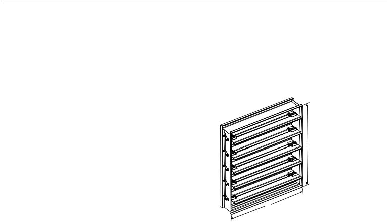
NOTE: Damper area is measured using the H and W dimensions.
H
W
M20587
Measuring Damper Area
1.Calculate the damper area in square feet by multiplying the H dimension by the W dimension.
2.Multiply the damper area by the lb-in. per square foot value from Table 2 on page 9.
NOTE: The minimum lb-in. per square foot value that can accommodate tight closeoff and no leakage applications is 5, regardless of the value shown in the table.
3.Select the highest actuator torque value than the calculated value.
EXAMPLE:
Low leakage, parallel blade damper: H dimension = 48 in.
W dimension = 96 in.
Static pressure (in. w.c.) = 2 in. w.c. Face Velocity = 1000 fpm
48 in. x 96 in. ÷ 144 = 32 sq. ft.
32 sq. ft. x 7 lb-in./sq. ft. = 244 lb-in. where 7 lb-in./sq. ft = value from Table 2.
In this case you would need an actuator with a minimum nominal torque of 224 lb-in.
8

DD&CA
Damper And Actuator Sizing
Table 2. Approximate industry standard damper lb-in. per sq ft value.
|
|
|
Face Velocity (fpm)/ |
|
||
|
|
|
Static Pressure (in. wc |
|
||
|
|
|
|
|
|
|
Leakage |
Damper |
500/ |
1000/ |
1500/ |
2000/ |
2500/ |
|
Blades |
1 |
2 |
3 |
4 |
5 |
|
|
|
|
|
|
|
Low |
Parallel |
4 |
7 |
10.5 |
12 |
14 |
|
|
|
|
|
|
|
Low |
Opposed |
3 |
5 |
7.5 |
8.5 |
10 |
|
|
|
|
|
|
|
Standard |
Parallel |
3 |
4.5 |
6.5 |
7 |
8 |
|
|
|
|
|
|
|
Standard |
Opposed |
2 |
3 |
4.5 |
5 |
6 |
|
|
|
|
|
|
|
Damper Sizing
Dampers can be sized using two different methods; actual sizing and nominal sizing. When actual sizing is used the damper dimensions will be the same as the sizes ordered. For example, when a 24 inch x 24 inch D640 damper is ordered, it will be made such that the height is 24 inches and the width is 24 inches. When nominal sizing is used, the damper dimensions will be ¼ inch smaller than the sizes ordered. For example, when a 24 inch x 24 inch D640 is ordered, it will be made such that the height is 23.75 inches and the width is 23.75 inches. No special allowances are required for dampers that are constructed of multiple sections. For example, a damper that is 24 inch x 60 inch will be constructed of two sections. When ordered using nominal sizing, the damper size will be 23.75 inches high by 59.75 inches wide.
Actual sizing is commonly used when the exact size of the opening is known or if the damper is not meant to be installed inside an opening or duct. Nominal sizing, with its ¼ inch undersizing is commonly used when the damper will be installed inside an opening or duct and space is needed for positioning or seal material.
Honeywell’s sizing default is nominal sizing. If actual sizing is required, please make sure this is specified on the order. For more information on ordering Honeywell dampers, please contact your local Honeywell distributor or sales representative.
9
Damper And Actuator Sizing
HVAC performance depends largely upon airflow, and Honeywell Volume Control Dampers are built for both improved airflow and heavy-duty use. Honeywell has long been the leading source for airflow
control, with Volume Control Dampers that meet AMCA-certified Air Performance Standards, the highest established standards for commercial control dampers. Designed to minimize leakage, Honeywell dampers will give you efficient, trouble-free operation for years to come.
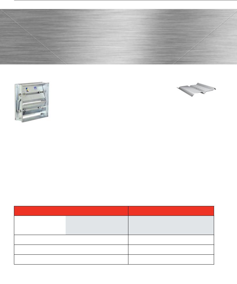
Standard Rectangular Dampers
Durable construction details are the cornerstone of Honeywell D1, D2 and D3 Volume Control Dampers. They feature heavy-duty hat channel frames for dependable operation inside ductwork. And all models have low-profile top and bottom frames, creating more free area while reducing pressure loss and reducing actuator torque.
The Right Choice
There’s a Honeywell Volume Control Damper that’s just right for your application. The D1 airfoil extremely low leakage damper presents a lower resistance to airflow typically used in high pressure systems.
The D2 ultra-low leakage damper keeps leakage to a minimum with blade and jamb seals, and is designed for mediumto high-pressure and velocity systems. The D3 low leakage damper is ruggedly built for applications in medium pressure and velocity systems.
3-V Blades - D2 and D3 Dampers
Honeywell Volume Control Dampers feature a 3-V design that’s proven to
meet higher-level system requirements
while minimizing flow-through system loss. Blades are fabricated from a single thickness of 16-gauge galvanized steel with three horizontal structural V-grooves running the length of the blade.
Applications And Operation
Honeywell Volume Control Dampers are designed to control airflow volume in mediumto high-pressure and velocity HVAC systems. Typical applications include volume control of airflow in zoning, air handler unit or economizer applications. Dampers are designed to operate with a wide range of Honeywell electric and pneumatic actuators. Operating range is from 2000 to 4000 fpm, and 2.5 to 6
inch wg. Spring return and non-spring return actuators are available with a wide range of output torque ratings to deliver the precise power needed for your damper application.
Blade Design
Airfoil Blades - D1 Dampers
Honeywell Airfoil Volume Control Dampers feature blades constructed of double skin galvanized steel. This design presents a lower resistance
to airflow and has strength that is typically used in high pressure systems.
Certified Performance
Honeywell certifies that models D2 and D3 are licensed to bear the AMCA Seal. The ratings shown are based on tests and procedures performed in accordance with AMCA Publication 511 and comply with the requirements of the AMCA Certified Ratings Programs. The AMCA Certified Ratings Seal applies to air performance ratings only.
|
|
Material |
|
|
Frame |
|
Blade |
||||||
|
|
|
|
Gauge |
|
Seals |
|||||||
|
|
|
|
|
|
|
|
||||||
|
Galvanized |
|
Stainless |
|
Aluminum |
|
|
|
|
|
Vinyl |
|
Silicone |
S — Standard |
|
|
16 |
|
14 |
|
12 |
|
|||||
|
|
|
|
|
|
|
|
|
|
|
|
|
|
O — Optional |
|
|
|
|
|
|
|
|
|
|
|
|
|
|
|
|
|
|
|
|
|
|
|
|
|
|
|
D1 Airfoil Extremely Low Leakage |
S |
|
O |
|
n/a |
S |
|
O |
|
O |
n/a |
|
S |
Volume Control Damper |
|
|
|
|
|
||||||||
|
|
|
|
|
|
|
|
|
|
|
|
|
|
D2 Ultra-Low Leakage |
S |
|
O |
|
O |
S |
|
O |
|
O |
S |
|
O |
Volume Control Damper |
|
|
|
|
|
||||||||
|
|
|
|
|
|
|
|
|
|
|
|
|
|
D3 Low Leakage Volume |
S |
|
O |
|
O |
S |
|
O |
|
O |
n/a |
|
n/a |
Control Damper |
|
|
|
|
|
||||||||
|
|
|
|
|
|
|
|
|
|
|
|
|
|
|
|
|
|
|
|
|
|
|
|
|
|
|
|
|
Bearings |
Axles |
Linkage |
|
|
Flange |
|
|
|||||||||
|
Material |
|
|
|
|
||||||||||||
|
|
|
|
|
|
|
|
|
|
|
|
|
|
|
|||
Synthetic |
|
Bronze |
|
Stainless |
Steel |
|
Stainless |
Steel |
|
Stainless |
None |
|
Single |
|
Double |
|
Reverse |
|
|
|
|
|
|
|
|||||||||||
S |
O |
|
O |
S |
|
O |
S |
|
O |
S |
|
O |
|
O |
|
O |
|
S |
O |
|
O |
S |
|
O |
S |
|
O |
S |
|
O |
|
O |
|
O |
|
S |
O |
|
O |
S |
|
O |
S |
|
O |
S |
|
O |
|
O |
|
O |
|
|
|
|
|
|
|
|
|
|
|
|
|
|
|
|
|
|
|
For a copy of the specification sheet the D1 (63-2671) or D2 and D3 (63-2398), visit customer.honeywell.com.
10
DD&CA
Damper And Actuator Sizing
Standard Round Dampers |
Custom Dampers |
D690 and DM7600 Round Dampers. The 6” to 16” round dampers are used in zoning systems to control airflow in a round duct. These dampers come with neoprene and silicone seals for tight close off and low leakage. The DM7600 includes an actuator that is already attached to the round damper.
Need a custom damper? Contact the Take-Off Service. Below is a sample list of the products we frequently quote.
Custom Rectangular Dampers
Number |
Description |
|
|
VCD34 |
Galvanized Insulated Airfoil Damper |
|
|
VCD40 |
Aluminum Narrow Frame Airfoil Damper |
|
|
VCD42 |
Aluminum Airfoil Damper (Galvanized Frame) |
|
|
VCD43 |
Aluminum Airfoil Damper |
|
|
VCD45 |
Aluminum thermally broken insulated Damper |
|
|
Custom Round Dampers
Number |
Description |
|
|
VCDR53 |
Galvanized Round Damper – to 24 inches |
|
|
VCDRM53 |
Galvanized Round Multi-Blade Damper – |
|
to 36 inches |
|
|
Specification Take-Off Service
1.Submit your information in one of the following ways:
a)Email to takeoff.service@honeywell.com (preferred)
b)Fax toll-free to 1-877-880-3386 (local: 1-612-951-1238)
2.Include your desired turn-around time.
3.Take-Off Service staff will send you a confirmation that your email or fax was received.
We always attempt to have your request finished as soon as possible. Please note, however, that the quality of the submitted information largely determines the turn-around time. We will work closely with you to ensure that we have enough information to move forward as quickly as possible.
4.A final product schedule document will be returned to you following take-off completion.
Included In the Final Take-Off Document
We send a comprehensive spreadsheet, which contains:
•A complete product schedule
•Base price
•Directions on how to order Honeywell products
•Links to product submittals
•Quote identification number
Questions
Don’t see what you need?
Take-Off Service Contact Information: Toll-free: 1-888-664-4092
Local: 1-612-951-1027
If you have questions about the Honeywell Take-Off Service, please call the dedicated Take-Off Service phone number or email us at takeoff.service@honeywell.com.
Direct Coupled Actuators
Spring Return,
Low Torque
Spring Return,
High Torque
Non-Spring Return,
Low Torque
Non-Spring Return,
High Torque
Direct coupled actuators quick selection guide
Precise, reliable performance. Lasting value. Ease of installation. Everything you look for in directcoupled actuators hinges on quality. And quality engineering is what makes Honeywell’s complete line of actuators the top performers in the industry. Our global engineering team designs and tests our direct-coupled actuators to exceed rigorous global standards — and to meet Honeywell’s own demanding life testing.
But we don’t stop there. Thanks to our continuous improvement process, Honeywell actuators are now easier than ever to install. You’ll also benefit from consistent wiring regardless of signal type, common accessories and a simplified selection process.
Honeywell’s complete line of building control products, including valves and actuators, are already proven in more than three million buildings worldwide. So when you need spring or nonspring return actuators for your damper and valve applications, specify Honeywell. We make precision easy.
Easy-to-select MODEL numbers
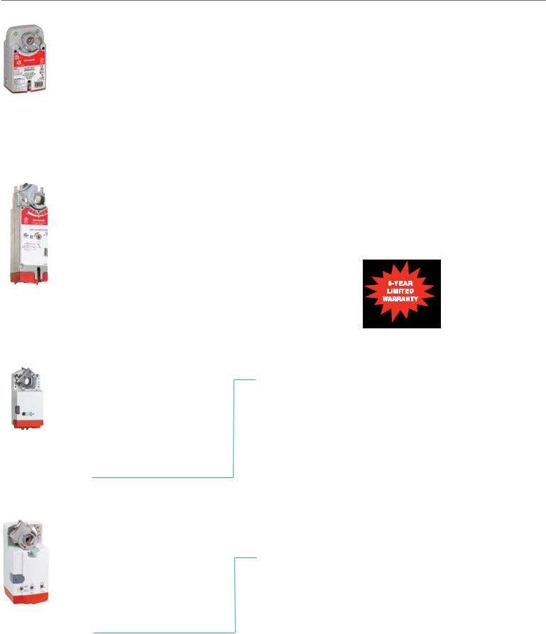
MS and MN Families
Improve Installation Time
•Self-centering shaft adapter provides mounting flexibility and greater clamping force.
•Common wiring among families for every signal saves installation time.
Decrease Material Cost
•Detachable access cover allows direct wiring without a junction box.
Reduce Inventory
•Signal mode switch adapts models to twoposition, floating (tri-state), or modulating (proportional) applications.
Increase Control and Accuracy
•More than 200 reposition steps for modulating models provide precise control.
MS 75 10 A 2 2 XX
Fail Safe Mode |
|
|
|
|
|
|
|
|
|
|
|
System Controlled Numbers |
||
• MS Spring Return |
|
|
|
|
|
Auxiliary Switches |
|
|||||||
• MN Non-Spring Return |
|
|
|
|
|
|||||||||
Input Signal Type |
|
|
|
|
|
|
|
|
|
• 0 No Internal Switches |
||||
|
|
|
|
• 2 Two Internal Switches |
||||||||||
• 41 Two-Position, 100-250 Vac |
|
|
|
|
|
|
Feedback |
|
||||||
• 61 Floating, 24 Vac/dc |
|
|
|
|||||||||||
• 75 Modulating/Floating, 24 Vac/dc |
|
|
|
• 1 No Feedback |
||||||||||
• 81 Two-Position, 24 Vac/dc |
|
|
• 2 Voltage Feedback |
|||||||||||
Torque |
|
|
Application Type |
|
||||||||||
• 03 Nm = 27 in-lb |
|
• A Standard Model |
||||||||||||
• 05 Nm = 44 in-lb |
|
• H Enhanced Model |
||||||||||||
• 10 Nm = 88 in-lb |
|
|
|
|
||||||||||
• 20 Nm = 175 in-lb |
|
|
|
|
||||||||||
• 34 Nm = 300 in-lb |
|
|
|
|
||||||||||
ML Family
ML 61 61 B 2 XXX |
|||||||||||
Fail Safe Mode |
|
|
|
|
|
|
|
|
|
System Controlled Numbers |
|
• ML Non-Spring Return |
|
|
|
|
|
|
|
Declutch |
|
||
|
|
|
|
|
|
|
|
|
|||
Input Signal Type |
|
|
|
|
|
|
|
• 1 Standard |
|||
• 61 Floating, 24 Vac |
|
|
|
|
|
|
|
• 2 Includes Declutch Function |
|||
• 71 Modulating, 24 Vac |
|
|
|
|
|
|
|
Feedback & Conduit |
|
||
|
|
|
|
|
|
|
|
|
|||
Torque |
|
|
|
|
|
|
|
• A Feedback w/Accessory |
|||
• 61 (4 Nm) = 35 in-lb |
|
|
|
|
|
|
|
• B Standard |
|||
• 74 (8 Nm) = 70 in-lb |
|
|
|
|
|
|
|
• C Feedback w/Accessory and |
|||
Cover w/Conduit Connections
• D Cover w/Conduit Connections
12
Direct Coupled Actuators
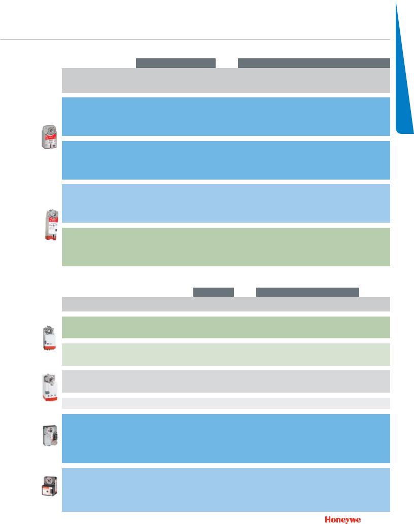
spring return
|
|
|
Running Time |
Power Supply |
|
|
Control Input/Output |
|
Auxiliary Knob |
|||||
|
|
|
|
|
|
|
|
|
|
|
|
|
|
|
|
|
|
|
|
|
|
|
|
|
|
|
Adj. |
|
Internal |
|
Order |
Approximate |
|
Spring |
|
|
|
|
0/2-10 |
3 kOhm |
Feedback |
Zero |
SPDT |
Minimum |
|
Specification |
Area of Damper |
Drive |
Return |
24 |
120-230 |
VA Rating |
|
Vdc, |
NTC, |
(0/2-10 |
and |
Auxiliary |
Position |
|
Number |
(4.5 lb-in/sq. ft.) |
(seconds) |
(seconds) |
Vac/dc |
Vac |
(Running) |
On/Off |
Floating |
3-Position |
Vdc) |
Span |
Switches |
Potentiometer |
|
|
|
|
|
|
|
|
|
|
|
|
|
|
|
|
S03 Series (3 Nm, |
27 lb-in) |
|
|
|
|
|
|
|
|
|
|
|
|
|
MS8103A1030 |
6 |
45 |
<25 |
• |
|
|
• |
|
|
|
|
0 |
|
|
MS8103A1130 |
6 |
45 |
<25 |
• |
|
|
• |
|
|
|
|
1 |
|
|
MS4103A1030 |
6 |
45 |
<25 |
|
• |
|
• |
|
|
|
|
0 |
|
|
MS4103A1130 |
6 |
45 |
<25 |
|
• |
|
• |
|
|
|
|
1 |
|
|
MS7503A2030 |
6 |
90 |
<25 |
• |
|
|
|
• |
|
• |
|
0 |
|
|
MS7503A2130 |
6 |
90 |
<25 |
• |
|
|
|
• |
|
• |
|
1 |
|
|
MS7403A2030 |
6 |
90 |
<25 |
• |
|
|
|
• |
• |
• |
|
0 |
• |
|
S05 Series (5 Nm, |
44 lb-in) |
|
|
|
|
|
|
|
|
|
|
|
|
|
MS8105A1030 |
10 |
45 |
<25 |
• |
|
|
• |
|
|
|
|
0 |
|
|
MS8105A1130 |
10 |
45 |
<25 |
• |
|
|
• |
|
|
|
|
1 |
|
|
MS4105A1030 |
10 |
45 |
<25 |
|
• |
|
• |
|
|
|
|
0 |
|
|
MS4105A1130 |
10 |
45 |
<25 |
|
• |
|
• |
|
|
|
|
1 |
|
|
MS7505A2030 |
10 |
90 |
<25 |
• |
|
|
|
• |
|
• |
|
0 |
|
|
MS7505A2130 |
10 |
90 |
<25 |
• |
|
|
|
• |
|
• |
|
1 |
|
|
MS7405A2030 |
10 |
90 |
<25 |
• |
|
|
|
|
• |
• |
|
0 |
• |
|
S10 Series (10 Nm, |
88 lb-in) |
|
|
|
|
|
|
|
|
|
|
|
|
|
MS8110A1008 |
20 |
45 |
<25 |
• |
|
|
• |
|
|
|
|
0 |
|
|
MS8110A1206 |
20 |
45 |
<25 |
• |
|
|
• |
|
|
|
|
2 |
|
|
MS4110A1002 |
20 |
45 |
<25 |
|
• |
|
• |
|
|
|
|
0 |
|
|
MS4110A1200 |
20 |
45 |
<25 |
|
• |
|
• |
|
|
|
|
2 |
|
|
MS7510A2008 |
20 |
90 |
<25 |
• |
|
|
|
• |
|
• |
|
0 |
|
|
MS7510A2206 |
20 |
90 |
<25 |
• |
|
|
|
• |
|
• |
|
2 |
|
|
MS7510H2209 |
20 |
90 |
<25 |
• |
|
|
|
|
|
• |
• |
2 |
|
|
S20 Series (20 Nm, |
175 lb-in) |
|
|
|
|
|
|
|
|
|
|
|
|
|
MS8120A1007 |
39 |
45 |
<25 |
• |
|
|
• |
|
|
|
|
0 |
|
|
MS8120A1205 |
39 |
45 |
<25 |
• |
|
|
• |
|
|
|
|
2 |
|
|
MS4120A1001 |
39 |
45 |
<25 |
|
• |
|
• |
|
|
|
|
0 |
|
|
MS4120A1209 |
39 |
45 |
<25 |
|
• |
|
• |
|
|
|
|
2 |
|
|
MS7520A2007 |
39 |
90 |
<25 |
• |
|
|
|
• |
|
• |
|
0 |
|
|
MS7520A2205 |
39 |
90 |
<25 |
• |
|
|
|
• |
|
• |
|
2 |
|
|
MS7520H2208 |
39 |
90 |
<25 |
• |
|
|
|
|
|
• |
• |
2 |
|
non-spring return
|
|
|
|
|
Power Supply |
|
|
Control Input/Output |
|
|
|
|
|
|
|||
|
|
|
|
|
|
|
|
|
|
|
|
|
|
||||
|
Order Specification |
|
Approximate Area of |
Running |
|
|
VA Rating |
On/Off, |
|
|
|
Feedback |
SPDT Auxiliary |
||||
|
Number |
|
Damper (4.5 lb-in/sq. ft.) |
Time |
24 Vac/dc |
24 Vac |
(Running) |
Floating |
0/2-10 Vdc |
2-10 Vdc |
|
(0/2-10 Vdc) |
|
|
|
Switches |
|
|
|
|
|
|
|
|
|
|
|
|
|
|
|
|
|
|
|
|
N05 Series (5 Nm, 44 lb-in) |
|
|
|
|
|
|
|
|
|
|
|
|
|
|
|
|
|
MN6105A1011 |
|
10 |
90 |
• |
|
|
• |
|
|
|
|
0 |
||||
|
MN6105A1201 |
|
10 |
90 |
• |
|
|
• |
|
|
|
|
2 |
||||
|
MN7505A2001 |
|
10 |
90 |
• |
|
|
|
|
|
|
• |
0 |
||||
|
MN7505A2209 |
|
10 |
90 |
• |
|
|
|
|
|
|
• |
2 |
||||
|
N10 Series (10 Nm, 88 lb- |
in) |
|
|
|
|
|
|
|
|
|
|
|
|
|
|
|
|
MN6110A1003 |
|
20 |
90 |
• |
|
|
• |
|
|
|
|
0 |
||||
|
MN6110A1201 |
|
20 |
90 |
• |
|
|
• |
|
|
|
|
2 |
||||
|
MN7510A2001 |
|
20 |
90 |
• |
|
|
• |
• |
|
|
• |
0 |
||||
|
MN7510A2209 |
|
20 |
90 |
• |
|
|
• |
• |
|
|
• |
2 |
||||
|
N20 Series (20 Nm, 175 lb |
-in) |
|
|
|
|
|
|
|
|
|
|
|
|
|
|
|
|
MN6120A1002 |
|
39 |
90 |
• |
|
|
• |
|
|
|
|
0 |
||||
|
MN6120A1200 |
|
39 |
90 |
• |
|
|
• |
|
|
|
|
2 |
||||
|
MN7220A2007 |
|
39 |
90 |
• |
|
|
|
• |
|
|
• |
0 |
||||
|
MN7220A2205 |
|
39 |
90 |
• |
|
|
|
• |
|
|
• |
2 |
||||
|
N34 Series (34 Nm, 300 lb |
-in) |
|
|
|
|
|
|
|
|
|
|
|
|
|
|
|
|
MN6134A1003 |
|
67 |
90 |
• |
|
|
• |
|
|
|
|
0 |
||||
|
MN7234A2008 |
|
67 |
90 |
• |
|
|
|
• |
|
|
|
2 |
||||
|
ML6161/7161 (4 Nm, 35 lb |
-in) |
|
|
|
|
|
|
|
|
|
|
|
|
|
|
|
|
ML6161A2009 |
|
8 |
90 |
|
• |
1.8 |
• |
|
|
|
w/ accessory |
0 |
||||
|
ML6161A2017 |
|
8 |
420 |
|
• |
1.8 |
• |
|
|
|
w/ accessory |
0 |
||||
|
ML6161A2025 |
|
8 |
180 |
|
• |
1.8 |
• |
|
|
|
w/ accessory |
0 |
||||
|
ML6161B2024 |
|
8 |
90 |
|
• |
1.8 |
• |
|
|
|
|
0 |
||||
|
MS6161B2032 |
|
8 |
420 |
|
• |
1.8 |
• |
|
|
|
|
0 |
||||
|
ML6161B2073 |
|
8 |
180 |
|
• |
1.8 |
• |
|
|
|
|
0 |
||||
|
ML6161C2007 |
|
8 |
90 |
|
• |
1.8 |
• |
|
|
|
w/ accessory |
0 |
||||
|
ML6161D2006 |
|
8 |
90 |
|
• |
1.8 |
• |
|
|
|
|
0 |
||||
|
MS7161A2008 |
|
8 |
90 |
|
• |
5.4 |
|
|
• |
|
|
0 |
||||
|
ML6174/7174 (8 Nm, 70 lb |
-in) |
|
|
|
|
|
|
|
|
|
|
|
|
|
|
|
|
ML6174A2002 |
|
16 |
90 |
|
• |
2.4 |
• |
|
|
|
w/ accessory |
0 |
||||
|
ML6174A2010 |
|
16 |
180 |
|
• |
2.4 |
• |
|
|
|
w/ accessory |
0 |
||||
|
ML6174B2019 |
|
16 |
90 |
|
• |
2.4 |
• |
|
|
|
|
0 |
||||
|
ML6174B2035 |
|
16 |
420 |
|
• |
2.4 |
• |
|
|
|
|
0 |
||||
|
ML6174D2009 |
|
16 |
90 |
|
• |
2.4 |
• |
|
|
|
|
0 |
||||
|
ML6174E2008 |
|
16 |
90 |
|
• |
2.4 |
• |
|
|
|
|
0 |
||||
|
ML7174A2001 |
|
16 |
90 |
|
• |
5.4 |
• |
|
|
|
|
0 |
||||
|
ML7174E2007 |
|
16 |
90 |
|
• |
5.4 |
• |
|
|
|
|
0 |
||||
1 Consult Tradeline catalog for additional models. |
|
|
|
|
|
|
|
|
|
|
|
|
|
13 |
|||
|
|
|
|
|
|
|
|
|
|
|
|
|
|||||
2 Assumes standard 1000 fpm system with parallel blade damper. Approximate square foot. |
|
|
|
|
|
|
|
|
|
|
|||||||
|
|
|
|
|
|
|
|
||||||||||
SelectionDCA

Fire & Smoke Actuators
Honeywell’s complete line of two-position, fast-acting springreturn actuators meet all of your needs for fire and smoke control applications. All models are designed to meet the UL-555 and UL-555S high temperature requirements for fire dampers and combined fire and smoke dampers.
Safety First
As a life safety system component Honeywell is dedicated to meeting the UL-555 and UL-555S requirements. The elevated temperature test can be performed at the temperature ratings of 250ºF or 350ºF. Honeywell only offers models at 350ºF to
meet UL-555 and UL-555S for fire and combined fire and smoke applications to support the highest level of safety for building occupants.
Largest Torque Range in the Industry
Honeywell’s fire and smoke actuators are available in 30, 80 and 175 lb-in with the 175 lb-in being the highest torque commercial fire and smoke actuator available on the market today.
Key Features and Benefits
•Integral spring return that ensures the proper level of torque
•Patented design that eliminated limit switches, reducing power consumption
•Reliable service in smoke control systems requiring
Underwriter’s Laboratories Inc. UL-555 and UL-555S
•Robust die-cast aluminum housing ensures
•Full life of two-position spring return fire and smoke actuators rated up to 350ºF for all critical applications
•Fast acting with a maximum spring return timing of 15 seconds
•No audible noise during holding
|
Torque |
Voltage |
Spring Direction |
Description |
Number of internal |
Model Number |
|
|
Auxiliary Switch |
||||||
|
|
|
|
|
|
|
|
|
|
|
|
|
|
|
|
|
|
|
120 Vac |
CCW |
|
External* |
ML4115A1009 |
|
|
|
CW |
Fire and smoke, fast acting, |
External* |
ML4115B1008 |
|
|
|
|
|
||||
|
|
|
|
CCW |
External* |
ML4115C1007 |
|
|
30 lb-in (3.4 Nm) |
230 Vac |
two position spring return, UL-555 |
||||
|
CW |
External* |
ML4115D1006 |
||||
|
|
|
|
and UL-555S ratings up to 350ºF |
|||
|
|
|
24 Vac |
CCW |
External* |
ML8115A1005 |
|
|
|
|
|
||||
|
|
|
CW |
|
External* |
ML8115B1004 |
|
|
|
|
|
|
|||
|
|
|
120 Vac |
CW |
|
External* |
MS4209F1007 |
|
|
|
CCW |
Fire and smoke, fast acting, |
External* |
MS4309F1005 |
|
|
|
|
|
||||
|
|
|
|
CW |
External* |
MS4709F1014 |
|
|
80 lb-in |
(9 Nm) |
230 Vac |
two position spring return, UL-555 |
|||
|
CCW |
External* |
MS4809F1012 |
||||
|
|
|
|
and UL555S ratings up to 350ºF |
|||
|
|
|
24 Vac |
CW |
External* |
MS8209F1003 |
|
|
|
|
|
||||
|
|
|
CCW |
|
External* |
MS8309F1001 |
|
|
|
|
|
|
|||
|
|
|
|
|
|
|
|
|
|
|
120 Vac |
|
|
0 |
MS4120F1006 |
|
|
|
|
Fire and smoke, fast acting, |
2 SPST |
MS4120F1204 |
|
|
|
|
|
|
|||
|
|
|
|
|
0 |
MS4620F1005 |
|
|
175 lb-in |
(20 Nm) |
230 Vac |
Reversible Design |
two position spring return, UL-555 and |
||
|
2 SPST |
MS4620F1203 |
|||||
|
|
|
|
|
UL-555S ratings up to 350ºF |
||
|
|
|
24 Vac |
|
0 |
MS8120F1002 |
|
|
|
|
|
|
|||
|
|
|
|
|
2 SPST |
MS8120F1200 |
|
|
|
|
|
|
|
||
Note: Honeywell's spring return fire and smoke actuators are designed to pass UL-555 and UL-555S 350ºF requirements. They are not designed for HVAC applications. UL-555 and UL-555S requires that all new construction fire and smoke damper jobs have the actuator assembled and tested at the damper manufacturer. A like for like retrofit replacement or technically equal UL-555 and UL-555S approved device is recommended.
14

Section 2: Valve Selection |
|
Control Valve Applications .......................................................... |
17 |
Control Valve Selection Criteria .................................................. |
18 |
2-Way.................................................................................... |
18 |
3-Way.................................................................................... |
20 |
Fan Coil and Zone Valves........................................................... |
22 |
Cartridge Cage Valves................................................................ |
24 |
Cartridge Globe Valves............................................................... |
26 |
Control Ball Valves ½ - 3” |
|
2-Way NPT NEMA 2.............................................................. |
28 |
2-Way NPT NEMA 3R........................................................... |
30 |
Control Ball Valves ½ - 2 ½” |
|
3-Way NPT NEMA 2.............................................................. |
32 |
3-Way NPT NEMA 3R.......................................................... |
33 |
Flanged Control Ball Valves 4”- 6” |
|
2-Way Flanged NEMA 2+3R.................................................. |
34 |
3-Way Flanged NEMA 2+3R.................................................. |
35 |
NPT Globe Valves ½-3” |
|
With Dedicated Valve Actuators............................................. |
36 |
With Direct Coupled Actuators.............................................. |
38 |
Flanged Globe Valves 2 ½ -3” |
|
With Direct Coupled Actuators.............................................. |
42 |
Threaded and Flanged Globe Valves 2”-3” |
|
With Tandem Linked Direct Coupled Actuators.................... |
46 |
Flanged Globe Valves 2 ½ - 3” |
|
With Dedicated Valve Actuators............................................. |
48 |
Flanged Globe Valves 4”-6” |
|
With Tandem Linked Direct Coupled Actuators..................... |
52 |
With Dedicated Valve Actuators............................................. |
54 |
Flanged Cage Valves 2 ½ - 6”.................................................... |
55 |
NPT Globe Valves ½ -3” |
|
With Pneumatic Actuators..................................................... |
56 |
Flanged Globe Valves 2 ½ - 3” |
|
With Pneumatic Actuators..................................................... |
60 |
Flanged Globe Valves 4”- 6” |
|
With Pneumatic Actuators..................................................... |
64 |
Resilient Seat Butterfly Valves |
|
2-Way Electrically-Actuated Control....................................... |
66 |
3-Way Electrically-Actuated Control....................................... |
68 |
2-Way Pneumatically-Actuated Control................................. |
72 |
3-Way Pneumatically-Actuated Control................................. |
74 |
Selection Valve
15

16

Control Valve Applications
Control Valve Applications |
Selection Valve |
17 |

Control Valve Selection Criteria
2-Way
|
|
|
|
|
|
Unitary |
|
|
|
Globe |
|
|
||
|
|
|
|
Fan Coil |
|
Cartridge |
Cartridge |
|
Threaded |
|
|
Flanged |
|
|
|
|
|
|
|
Cage |
Globe |
|
|
|
|
||||
|
|
|
|
|
|
|
|
|
|
|
|
|
||
Attribute |
Specification |
VU52 |
|
VU53 |
VCzA/B |
V58x2 |
V5011N... |
V5011F |
V5011G |
V5011A |
V5011B |
VGF2xS |
||
|
1/2" |
[DN15] |
• |
|
• |
• |
• |
• |
|
|
|
|
|
|
|
3/4" |
[DN20] |
• |
|
• |
• |
• |
• |
|
|
|
|
|
|
|
|
1" |
[DN25] |
• |
|
• |
• |
|
• |
|
|
|
|
|
|
1 1/4" |
[DN32] |
|
|
|
• |
|
• |
|
|
|
|
|
|
|
1 1/2" |
[DN40] |
|
|
|
|
|
• |
|
|
|
|
|
|
Pipe Size |
|
2" |
[DN50] |
|
|
|
|
|
• |
|
|
|
|
|
2 1/2" |
[DN65] |
|
|
|
|
|
|
• |
• |
• |
|
• |
||
|
|
|
|
|
|
|
|
|||||||
|
|
3" |
[DN80] |
|
|
|
|
|
|
• |
• |
• |
|
• |
|
|
4" |
[DN100] |
|
|
|
|
|
|
|
|
• |
• |
• |
|
|
5" |
[DN125] |
|
|
|
|
|
|
|
|
• |
• |
• |
|
|
6" |
[DN150] |
|
|
|
|
|
|
|
|
• |
• |
• |
|
Other |
(maximum size) |
|
|
|
|
|
|
|
|
|
|
|
|
|
|
Sweat |
• |
|
• |
• |
• |
|
|
|
|
|
|
|
Pipe Fittings |
NPT Internal Thread |
• |
|
• |
• |
• |
• |
• |
• |
|
|
|
||
Inverted Flare |
• |
|
• |
• |
|
|
|
|
|
|
|
|||
|
|
|
|
|
|
|
|
|
||||||
|
|
ANSI Flange |
|
|
|
|
|
|
|
|
• |
• |
• |
|
|
ANSI 125/150 |
|
|
|
|
|
• |
• |
• |
• |
• |
• |
||
Static Pressure |
ANSI 250/300 |
|
|
|
|
|
|
|
|
|
|
• |
||
|
|
|
Other |
300 psi |
|
300 psi |
230 psi |
|
|
|
|
|
|
|
|
|
Chilled Water |
• |
|
• |
• |
• |
• |
• |
• |
• |
• |
• |
|
Media |
|
Hot Water |
• |
|
• |
• |
• |
• |
• |
• |
• |
• |
• |
|
Low Pressure Steam |
|
|
|
|
|
N1, N3 |
• |
• |
• |
• |
• |
|||
|
|
|
|
|
|
|||||||||
|
High Pressure Steam |
|
|
|
|
|
N2 |
|
• |
|
|
• |
||
Flow Capacity, Cv |
Multiple ratings per pipe size |
• |
|
• |
• |
• |
• |
• |
• |
|
|
|
||
One rating/size above 1/2" |
|
|
|
|
|
• |
• |
• |
• |
• |
• |
|||
|
|
|
|
|
|
|||||||||
|
Direct Acting **** |
|
|
|
|
|
N1, N2 |
• |
• |
• |
|
• |
||
Valve Action |
Reverse Acting ***** |
|
|
|
• |
• |
N3 |
|
|
|
• |
|
||
|
Rotary N.O. |
• |
|
|
|
|
|
|
|
|
|
|
||
|
|
|
|
|
|
|
|
|
|
|
|
|||
|
|
Rotary N.C. |
|
|
• |
|
|
|
|
|
|
|
|
|
|
Equal Percentage |
|
|
|
|
• |
• |
• |
|
• |
• |
• |
||
Flow Characteristic |
Modified Equal Percentage |
|
|
|
• |
|
|
|
|
|
|
|
||
|
Linear |
|
|
|
• |
|
• |
|
• |
|
|
• |
||
|
|
|
|
|
|
|
|
|
||||||
|
|
Quick Open |
• |
|
• |
• |
|
|
|
|
|
|
|
|
Close-off |
High** |
(100 psid minimum) |
|
|
|
|
• |
|
|
|
|
|
|
|
Medium |
(40 psid minimum) |
|
|
|
• |
• |
|
|
|
|
|
|
||
pressure*** |
|
|
|
|
|
|
|
|
|
|||||
Varies with actuator |
• |
|
• |
|
|
• |
• |
• |
• |
• |
• |
|||
|
|
|
|
|||||||||||
|
ANSI Class III (0.10% Cv max.) |
|
|
|
|
0.02% |
0.05% |
|
|
|
|
• |
||
Maximum Seat |
ANSI Class IV (0.01% Cv max.) |
|
|
|
|
|
|
|
|
• |
• |
|
||
Leakage |
Bubble-tight design |
|
|
|
• |
|
|
|
|
|
|
|
||
|
Other (see product data literature) |
33 mL/m |
|
|
|
|
0.5% |
0.5% |
|
|
|
|||
|
High |
|
(50:1 minimum) |
|
|
|
|
• |
• |
• |
• |
• |
• |
• |
Rangeability |
Medium* |
(15~50:1) |
N/A |
|
• |
|
|
|
|
|
|
|
||
|
Low |
|
(under 15:1) |
|
|
|
|
|
|
|
|
|
|
|
|
Brass, plated brass, bronze |
|
|
|
|
|
N3 |
• |
|
• |
• |
|
||
Trim |
Brass plug /Stainless seat |
|
|
|
|
|
N1 |
|
|
|
|
|
||
Stainless Steel |
|
|
|
|
|
N2 |
|
• |
|
|
• |
|||
|
|
|
|
|
|
|
|
|
||||||
|
Resilient materials |
• |
|
• |
• |
• |
|
|
|
|
|
|
||
In-line |
|
Cartridge |
• |
|
• |
• |
• |
|
|
|
|
|
|
|
|
Packing |
|
|
|
|
|
• |
• |
• |
• |
• |
• |
||
Serviceability |
|
|
|
|
|
|
||||||||
|
Rebuild |
|
|
|
|
|
• |
• |
• |
• |
• |
|
||
|
|
|
|
|
|
|
|
|||||||
|
Electronic Modulating |
|
|
|
• |
• |
• |
• |
• |
• |
• |
• |
||
|
Tri-state floating |
|
|
|
• |
• |
• |
• |
• |
• |
• |
• |
||
|
Pulse Width Modulation |
|
|
|
• |
|
|
|
|
|
|
|
||
|
2-position low voltage |
• |
|
• |
• |
o |
• |
• |
• |
• |
• |
• |
||
Actuation Options |
2-position line voltage |
• |
|
• |
• |
|
• |
• |
• |
• |
• |
• |
||
Electric Spring Return |
• |
|
• |
|
• |
• |
• |
• |
• |
• |
• |
|||
|
|
|
||||||||||||
|
Electronic Fail Safe |
|
|
|
• |
|
|
|
|
|
|
|
||
|
Pneumatic, low pressure |
|
|
|
|
• |
• |
• |
• |
• |
• |
• |
||
|
Pnuematic bidirectional (Hi-Pr) |
|
|
|
|
|
|
|
|
|
|
|
||
|
Pnuematic spring return (Hi-Pr) |
|
|
|
|
|
|
|
|
|
|
|
||
Notes |
* Best used with supply water reset from outdoor air temperature. |
|
|
|
|
|
|
|
|
|||||
|
** Can dead-head pumps. Use with VFD-controlled pumps with maximum pressure cut-out |
|
|
|
|
|
|
|||||||
|
*** Maximum operating differential pressure. Static close-off pressure may be higher. Maximum pressure for quiet service may be less. |
|
|
|
||||||||||
18 |
**** Stem down to close |
|
|
|
|
|
|
|
|
|
|
|
||
***** Stem up to close |
|
|
|
|
|
|
|
|
|
|
|
|||

Control Valve Selection Criteria
2-Way
|
|
|
|
Globe |
Control Ball |
|
Butterfly |
|
||||||||
|
|
|
|
Pressure-Balanced |
Threaded |
Flanged |
Resilient Seat |
|
||||||||
|
|
|
|
|
|
|
|
|
|
|||||||
Attribute |
Specification |
V5862A3 |
VGF2xP |
VBN2 |
VBF2 |
VFF1 |
|
VFF2 |
|
|
|
|
|
|||
|
1/2" |
[DN15] |
|
|
• |
|
|
|
|
|
|
|
|
|
|
|
|
3/4" |
[DN20] |
|
|
• |
|
|
|
|
|
|
|
|
|
|
|
|
|
1" |
[DN25] |
• |
|
• |
|
|
|
|
|
|
|
|
|
|
|
1 1/4" |
[DN32] |
• |
|
• |
|
|
|
|
|
|
|
|
|
|
|
|
1 1/2" |
[DN40] |
• |
|
• |
|
|
|
|
|
|
|
|
|
|
|
Pipe Size |
|
2" |
[DN50] |
|
|
• |
|
• |
|
|
• |
|
||||
2 1/2" |
[DN65] |
|
• |
• |
|
• |
|
|
• |
|
|
|
|
|
||
|
|
|
|
|
|
|||||||||||
|
|
3" |
[DN80] |
|
• |
• |
|
• |
|
|
• |
|
||||
|
|
4" |
[DN100] |
|
• |
|
• |
• |
|
|
• |
|
||||
|
|
5" |
[DN125] |
|
• |
|
• |
• |
|
|
• |
|
||||
|
|
6" |
[DN150] |
|
• |
|
• |
• |
|
|
• |
|
||||
|
Other |
(maximum size) |
|
|
|
|
|
20" [DN500] |
|
|||||||
|
|
Sweat |
|
|
|
|
|
|
|
|
|
|
|
|
|
|
Pipe Fittings |
NPT Internal Thread |
• |
|
• |
|
|
|
|
|
|
|
|
|
|
||
Inverted Flare |
|
|
|
|
|
|
|
|
|
|
|
|
|
|||
|
|
|
|
|
|
|
|
|
|
|
|
|
|
|||
|
|
ANSI Flange |
|
• |
|
• |
• |
|
|
• |
|
|||||
|
ANSI 125/150 |
|
• |
|
• |
|
|
|
|
|
|
|
|
|
||
Static Pressure |
ANSI 250/300 |
|
|
|
|
|
|
|
|
|
|
|
|
|
||
|
|
|
Other |
230 psi |
360 psi |
|
|
250 psi |
|
|||||||
|
|
Chilled Water |
• |
• |
• |
• |
• |
|
|
• |
|
|||||
Media |
|
Hot Water |
• |
• |
• |
• |
• |
|
|
• |
|
|||||
Low Pressure Steam |
|
• |
|
|
|
|
|
|
|
|
|
|
|
|||
|
|
|
|
|
|
|
|
|
|
|
|
|
||||
|
High Pressure Steam |
|
• |
|
|
|
|
|
|
|
|
|
|
|
||
Flow Capacity, Cv |
Multiple ratings per pipe size |
• |
|
• |
• |
|
|
|
|
|
|
|
|
|
||
One rating/size above 1/2" |
|
• |
|
|
• |
|
|
• |
|
|
|
|
|
|||
|
|
|
|
|
|
|
||||||||||
|
Direct Acting **** |
• |
• |
|
|
|
|
|
|
|
|
|
|
|
||
Valve Action |
Reverse Acting ***** |
|
|
|
|
|
|
|
|
|
|
|
|
|
||
|
Rotary N.O. |
|
|
o |
o |
• |
|
|
o |
|
|
|
|
|
||
|
|
|
|
|
|
|
||||||||||
|
|
Rotary N.C. |
|
|
• |
• |
|
|
|
• |
|
|||||
|
Equal Percentage |
|
• |
|
|
|
|
|
|
|
|
|
|
|
||
Flow Characteristic |
Modified Equal Percentage |
|
|
• |
• |
• |
|
|
• |
|
||||||
|
Linear |
• |
• |
|
|
|
|
|
|
|
|
|
|
|
||
|
|
|
|
|
|
|
|
|
|
|
|
|
||||
|
|
Quick Open |
|
|
|
|
|
|
|
|
|
|
|
|
|
|
Close-off |
High** |
(100 psid minimum) |
• |
• |
• |
• |
• |
|
|
• |
|
|||||
Medium |
(40 psid minimum) |
|
|
|
|
• |
|
|
• |
|
|
|
|
|
||
pressure*** |
|
|
|
|
|
|
|
|||||||||
Varies with actuator |
|
|
|
|
|
|
|
|
|
|
|
|
|
|||
|
|
|
|
|
|
|
|
|
|
|
|
|
|
|||
|
ANSI Class III (0.10% Cv max.) |
|
|
|
|
|
|
|
|
|
|
|
|
|
||
Maximum Seat |
ANSI Class IV (0.01% Cv max.) |
• |
• |
• |
• |
• |
|
|
• |
|
||||||
Leakage |
Bubble-tight design |
|
|
|
|
• |
|
|
• |
|
||||||
|
Other (see product data literature) |
|
|
|
|
|
|
|
|
|
|
|
|
|
||
|
High |
|
(50:1 minimum) |
• |
• |
• |
• |
|
|
|
|
|
|
|
|
|
Rangeability |
Medium* |
(15~50:1) |
|
|
o |
|
|
|
|
|
|
|
|
|
|
|
|
Low |
|
(under 15:1) |
|
|
|
|
• |
|
|
• |
|
||||
|
Brass, plated brass, bronze |
|
|
• |
|
|
|
|
|
|
|
|
|
|
||
Trim |
Brass plug /Stainless seat |
|
|
|
|
|
|
|
|
|
|
|
|
|
||
Stainless Steel |
• |
• |
• |
• |
|
|
|
|
|
|
|
|
|
|||
|
|
|
|
|
|
|
|
|
|
|||||||
|
Resilient materials |
|
|
|
|
• |
|
|
• |
|
||||||
In-line |
|
Cartridge |
|
|
|
|
|
|
|
|
|
|
|
|
|
|
|
Packing |
• |
• |
• |
• |
|
|
|
|
|
|
|
|
|
||
Serviceability |
|
|
|
|
|
|
|
|
|
|
||||||
|
Rebuild |
|
|
|
• |
|
|
|
|
|
|
|
|
|
||
|
|
|
|
|
|
|
|
|
|
|
|
|
|
|||
|
Electronic Modulating |
• |
• |
• |
• |
• |
|
|
• |
|
||||||
|
Tri-state floating |
• |
• |
• |
• |
• |
|
|
• |
|
||||||
|
Pulse Width Modulation |
|
|
|
|
|
|
|
|
|
|
|
|
|
||
|
2-position low voltage |
|
• |
• |
• |
|
|
Limited |
|
|||||||
Actuation Options |
2-position line voltage |
|
• |
o |
o |
• |
|
|
• |
|
||||||
Electric Spring Return |
• |
• |
• |
• |
|
|
Limited |
|
|
|
|
|
||||
|
|
|
|
|||||||||||||
|
Electronic Fail Safe |
|
|
|
|
|
|
|
|
|
|
|
|
|
||
|
Pneumatic, low pressure |
|
• |
|
|
|
|
Limited |
|
|||||||
|
Pnuematic bidirectional (Hi-Pr) |
|
|
|
|
• |
|
|
• |
|
||||||
|
Pnuematic spring return (Hi-Pr) |
|
|
|
|
• |
|
|
• |
|
||||||
Notes |
* Best used with supply water reset from outdoor air temperature. |
|
|
|
|
|
|
|
|
|
|
|
||||
|
** Can dead-head pumps. Use with VFD-controlled pumps with maximum pressure cut-out |
|
|
|
|
|
|
|
|
|
||||||
|
*** Maximum operating differential pressure. Static close-off pressure may be higher. Maximum pressure for quiet service may be less. |
|||||||||||||||
|
**** Stem down to close |
|
|
|
|
|
|
|
|
|
|
|
|
19 |
||
|
***** Stem up to close |
|
|
|
|
|
|
|
|
|
|
|
|
|||
|
|
|
|
|
|
|
|
|
||||||||
Selection Valve

Control Valve Selection Criteria
3-Way
|
|
|
|
|
|
Unitary |
|
|
|
Globe |
|
|
||
|
|
|
|
|
Fan Coil |
Cartridge |
Cartridge Globe |
Threaded |
|
Flanged |
|
|||
|
|
|
|
|
Cage |
|
|
|||||||
|
|
|
|
|
|
|
|
|
|
|
|
|
|
|
Attribute |
Specification |
|
VU54 |
VCzM/N |
V58x3 |
V5863A3 |
V5013N... |
V5013B |
V5013C |
|
VGF3xLD |
VGF3xEM |
||
|
1/2" |
[DN15] |
|
• |
• |
• |
|
• |
|
|
|
|
|
|
|
3/4" |
[DN20] |
|
• |
• |
• |
|
• |
|
|
|
|
|
|
|
|
1" |
[DN25] |
|
• |
• |
|
• |
• |
|
|
|
|
|
|
1 1/4" |
[DN32] |
|
|
• |
|
• |
• |
|
|
|
|
|
|
|
1 1/2" |
[DN40] |
|
|
|
|
• |
• |
|
|
|
|
|
|
Pipe Size |
|
2" |
[DN50] |
|
|
|
|
|
• |
|
|
|
|
|
2 1/2" |
[DN65] |
|
|
|
|
|
|
• |
|
|
• |
• |
||
|
|
|
|
|
|
|
|
|
||||||
|
|
3" |
[DN80] |
|
|
|
|
|
|
• |
|
|
• |
• |
|
|
4" |
[DN100] |
|
|
|
|
|
|
• |
• |
|
• |
• |
|
|
5" |
[DN125] |
|
|
|
|
|
|
• |
• |
|
• |
• |
|
|
6" |
[DN150] |
|
|
|
|
|
|
• |
• |
|
• |
• |
|
Other |
(maximum size) |
|
|
|
|
|
|
|
|
|
|
|
|
|
|
Sweat |
|
• |
• |
• |
|
|
|
|
|
|
|
|
Pipe Fittings |
NPT Internal Thread |
|
• |
• |
• |
• |
• |
|
|
|
|
|
||
Inverted Flare |
|
• |
• |
|
|
|
|
|
|
|
|
|||
|
|
|
|
|
|
|
|
|
|
|||||
|
ANSI Flange |
|
|
|
|
|
|
• |
• |
|
• |
• |
||
|
ANSI 125/150 |
|
|
|
|
|
• |
• |
• |
|
• |
• |
||
Static Pressure |
ANSI 250/300 |
|
|
|
|
|
|
|
|
|
• |
• |
||
|
|
|
Other |
|
300 psi |
300 psi |
230 psi |
230 psi |
|
|
|
|
|
|
Media |
Chilled Water |
|
• |
• |
• |
• |
• |
• |
• |
|
• |
• |
||
|
Hot Water |
|
• |
• |
• |
• |
• |
• |
• |
|
• |
• |
||
|
|
|
|
|||||||||||
Flow Capacity, Cv |
Multiple ratings per pipe size |
|
• |
• |
• |
• |
• |
|
|
|
|
|
||
One rating/size above 1/2" |
|
|
|
|
|
• |
• |
• |
|
• |
• |
|||
|
|
|
|
|
|
|
||||||||
|
Mixing |
A-B-AB porting |
|
|
|
• |
• |
• |
• |
|
|
|
• |
|
Valve Action |
Mixing |
A-AB-B porting |
|
• |
• |
|
|
|
|
|
|
|
|
|
Diverting |
AB-B-A porting |
|
|
|
|
|
|
|
• |
|
• |
|
||
|
|
|
|
|
|
|
|
|
|
|||||
|
Diverting |
A-AB-B porting |
|
|
• |
|
|
|
|
|
|
|
|
|
|
Equal Percentage |
|
|
|
• |
|
• |
|
|
|
|
• |
||
A-port Flow |
Modified Equal Percentage |
|
|
• |
|
|
|
|
|
|
|
|
||
Characteristic |
|
Linear |
|
|
• |
|
• |
|
• |
• |
|
• |
|
|
|
Quick Open |
|
• |
• |
|
|
|
|
|
|
|
|
||
|
Modified Equal Percentage |
|
|
|
|
|
|
|
|
|
|
|
||
B-port Flow |
|
Linear |
|
|
• |
|
|
• |
• |
• |
|
• |
• |
|
Linear, Reduced Cv |
|
|
|
• |
• |
|
|
|
|
|
|
|||
Characteristic |
|
|
|
|
|
|
|
|
|
|||||
Total Constant Flow |
|
|
|
• |
• |
• |
• |
• |
|
• |
|
|||
|
|
|
|
|
|
|||||||||
|
Quick Open |
|
• |
|
|
|
|
|
|
|
|
|
||
Close-off |
High |
(60 psid minimum) |
|
|
• |
• |
• |
|
|
|
|
|
|
|
Medium |
(30 psid minimum) |
|
|
|
• |
|
|
|
|
|
|
|
||
pressure*** |
|
|
|
|
|
|
|
|
|
|
||||
|
Varies with actuator |
|
• |
|
|
|
• |
• |
• |
|
• |
• |
||
|
ANSI Class III (0.10% Cv max.) |
|
|
|
• |
• |
• |
|
|
|
• |
|
||
Maximum |
ANSI Class IV (0.01% Cv max.) |
|
|
|
|
|
|
• |
• |
|
|
|
||
Seat |
|
|
|
|
|
|
|
|
|
|
|
|
|
|
Bubble-tight design |
|
|
• |
|
|
|
|
|
|
|
|
|||
Leakage** |
|
|
|
|
|
|
|
|
|
|
||||
|
Other (see product data literature) |
|
33 mL/m |
|
|
|
|
|
|
|
|
A = 0.5% |
||
|
High |
(50:1 minimum) |
|
|
|
• |
• |
• |
• |
• |
|
• |
• |
|
Rangeability |
Medium* |
(15~50:1) |
|
N/A |
• |
|
|
|
|
|
|
|
|
|
|
Low |
(under 15:1) |
|
|
|
|
|
|
|
|
|
|
|
|
|
Brass, plated brass, bronze |
|
|
|
|
• |
• |
• |
• |
|
|
|
||
Trim |
Stainless Steel |
|
|
|
|
|
o |
|
|
|
• |
• |
||
|
Resilient materials |
|
• |
• |
• |
|
|
|
|
|
|
|
||
In-line |
|
Cartridge |
|
• |
• |
• |
|
|
|
|
|
|
|
|
|
Packing |
|
|
|
|
• |
• |
• |
• |
|
• |
• |
||
Serviceability |
|
|
|
|
|
|
||||||||
|
Rebuild |
|
|
|
|
|
• |
• |
• |
|
|
|
||
|
|
|
|
|
|
|
|
|
|
|||||
|
Electronic Modulating |
|
|
• |
• |
• |
• |
• |
• |
|
• |
• |
||
|
Tri-state floating |
|
|
• |
• |
• |
• |
• |
• |
|
• |
• |
||
|
Pulse Width Modulation |
|
|
• |
|
|
|
|
|
|
|
|
||
|
2-position low voltage |
|
• |
• |
o |
o |
• |
• |
• |
|
• |
• |
||
Actuation Options |
2-position line voltage |
|
• |
• |
|
|
• |
• |
• |
|
• |
• |
||
Electric Spring Return |
|
• |
|
• |
• |
• |
• |
• |
|
• |
• |
|||
|
|
|
|
|||||||||||
|
Electronic Fail Safe |
|
|
• |
|
|
|
|
|
|
|
|
||
|
Pneumatic, low pressure |
|
|
|
• |
|
• |
• |
• |
|
• |
• |
||
|
Pnuematic bidirectional (Hi-Pr) |
|
|
|
|
|
|
|
|
|
|
|
||
|
Pnuematic spring return (Hi-Pr) |
|
|
|
|
|
|
|
|
|
|
|
||
Notes |
* Best used with supply water reset from outdoor air temperature. |
|
|
|
|
|
|
|
|
|||||
|
** A port specification |
|
|
|
|
|
|
|
|
|
|
|||
|
*** A-port maximum operating differential pressure. Static close-off pressure may be higher. Maximum pressure for quiet service may be less. |
|
|
|||||||||||
|
**** Stem down to close |
|
|
|
|
|
|
|
|
|
|
|||
20 |
***** Stem up to close |
|
|
|
|
|
|
|
|
|
|
|||
"Limited" = not available in large sizes |
|
|
|
|
|
|
|
|
|
|
||||
|
|
|
|
|
|
|
|
|
|
Control Valve Selection Criteria |
||||||
|
|
|
|
|
|
|
|
|
|
|
|
|
|
|
|
|
|
|
|
|
|
|
|
|
|
|
|
|
|
|
|
3-Way |
|
|
|
|
|
|
|
|
|
|
|
|||||||
|
|
|
|
|
|
Control Ball |
|
Butterfly |
|
|
|
|
|
|||
|
|
|
|
|
|
Threaded |
Flanged |
Resilient Seat |
|
|||||||
|
|
|
|
|
|
|
|
|
|
|||||||
|
Attribute |
Specification |
|
VBN3 |
VBF3 |
VFF3 |
|
VFF6 |
|
|
|
|
|
|||
|
|
1/2" |
[DN15] |
|
• |
|
|
|
|
|
|
|
|
|
|
|
|
|
3/4" |
[DN20] |
|
• |
|
|
|
|
|
|
|
|
|
|
|
|
|
|
1" |
[DN25] |
|
• |
|
|
|
|
|
|
|
|
|
|
|
|
1 1/4" |
[DN32] |
|
• |
|
|
|
|
|
|
|
|
|
|
|
|
|
1 1/2" |
[DN40] |
|
• |
|
|
|
|
|
|
|
|
|
|
|
|
Pipe Size |
|
2" |
[DN50] |
|
• |
|
• |
|
|
• |
|
||||
|
2 1/2" |
[DN65] |
|
• |
|
• |
|
|
• |
|
|
|
|
|
||
|
|
|
|
|
|
|
||||||||||
|
|
|
3" |
[DN80] |
|
|
|
• |
|
|
• |
|
||||
|
|
|
4" |
[DN100] |
|
|
• |
• |
|
|
• |
|
||||
|
|
|
5" |
[DN125] |
|
|
• |
• |
|
|
• |
|
||||
|
|
|
6" |
[DN150] |
|
|
• |
• |
|
|
• |
|
||||
|
|
Other |
(maximum size) |
|
|
|
|
20" [DN500] |
|
|||||||
|
|
|
Sweat |
|
|
|
|
|
|
|
|
|
|
|
|
|
|
Pipe Fittings |
NPT Internal Thread |
|
• |
|
|
|
|
|
|
|
|
|
|
||
|
Inverted Flare |
|
|
|
|
|
|
|
|
|
|
|
|
|||
|
|
|
|
|
|
|
|
|
|
|
|
|
|
|||
|
|
ANSI Flange |
|
|
• |
• |
|
|
• |
|
||||||
|
|
ANSI 125/150 |
|
|
• |
|
|
|
|
|
|
|
|
|
||
|
Static Pressure |
ANSI 250/300 |
|
|
|
|
|
|
|
|
|
|
|
|
||
|
|
|
|
Other |
|
360 psi |
|
|
|
250 psi |
|
|||||
|
Media |
Chilled Water |
|
• |
• |
• |
|
|
• |
|
||||||
|
|
Hot Water |
|
• |
• |
• |
|
|
• |
|
|
|
|
|
||
|
|
|
|
|
|
|
||||||||||
|
Flow Capacity, Cv |
Multiple ratings per pipe size |
|
• |
• |
|
|
|
|
|
|
|
|
|
||
|
One rating/size above 1/2" |
|
|
|
• |
|
|
• |
|
|
|
|
|
|||
|
|
|
|
|
|
|
|
|||||||||
|
|
Mixing |
A-B-AB porting |
|
• |
• |
• |
|
|
|
|
|
|
|
|
|
|
Valve Action |
Mixing |
A-AB-B porting |
|
|
|
|
|
|
• |
|
|||||
|
Diverting |
AB-B-A porting |
|
• |
o |
• |
|
|
|
|
|
|
|
|
||
|
|
|
|
|
|
|
|
|
|
|
||||||
|
|
Diverting |
A-AB-B porting |
|
|
|
|
|
|
• |
|
|||||
|
|
Equal Percentage |
|
|
|
|
|
|
|
|
|
|
|
|
||
|
A-port Flow |
Modified Equal Percentage |
|
• |
• |
• |
|
|
• |
|
||||||
|
Characteristic |
|
Linear |
|
|
|
|
|
|
|
|
|
|
|
|
|
|
|
Quick Open |
|
|
|
|
|
|
|
|
|
|
|
|
||
|
|
Modified Equal Percentage |
|
|
|
• |
|
|
• |
|
||||||
|
B-port Flow |
|
Linear |
|
|
|
|
|
|
|
|
|
|
|
|
|
|
Linear, Reduced Cv |
|
• |
• |
|
|
|
|
|
|
|
|
|
|||
|
Characteristic |
|
|
|
|
|
|
|
|
|
|
|||||
|
Total Constant Flow |
|
|
|
|
|
|
|
|
|
|
|
|
|||
|
|
|
|
|
|
|
|
|
|
|
|
|
|
|||
|
|
Quick Open |
|
|
|
|
|
|
|
|
|
|
|
|
||
|
Close-off |
High |
(60 psid minimum) |
|
|
• |
• |
|
|
• |
|
|
|
|
|
|
|
Medium |
(30 psid minimum) |
|
• |
|
• |
|
|
• |
|
|
|
|
|
||
|
pressure*** |
|
|
|
|
|
||||||||||
|
Varies with actuator |
|
|
|
|
|
|
|
|
|
|
|
|
|||
|
|
|
|
|
|
|
|
|
|
|
|
|
|
|||
|
|
ANSI Class III (0.10% Cv max.) |
|
|
|
|
|
|
|
|
|
|
|
|
||
|
Maximum |
ANSI Class IV (0.01% Cv max.) |
|
• |
A-port |
• |
|
|
• |
|
||||||
|
Seat |
|
|
|
|
|
|
|
|
|
|
|
|
|
|
|
|
Bubble-tight design |
|
|
|
• |
|
|
• |
|
|
|
|
|
|||
|
Leakage** |
|
|
|
|
|
|
|||||||||
|
|
Other (see product data literature) |
|
|
B-port |
|
|
|
|
|
|
|
|
|
||
|
|
High |
(50:1 minimum) |
|
• |
• |
|
|
|
|
|
|
|
|
|
|
|
Rangeability |
Medium* |
(15~50:1) |
|
o |
|
|
|
|
|
|
|
|
|
|
|
|
|
Low |
(under 15:1) |
|
|
|
• |
|
|
• |
|
|
|
|
|
|
|
|
Brass, plated brass, bronze |
|
• |
|
|
|
|
|
|
|
|
|
|
||
|
Trim |
Stainless Steel |
|
|
• |
|
|
|
|
|
|
|
|
|
||
|
|
Resilient materials |
|
|
|
• |
|
|
• |
|
|
|
|
|
||
|
In-line |
|
Cartridge |
|
|
|
|
|
|
|
|
|
|
|
|
|
|
|
Packing |
|
• |
• |
|
|
|
|
|
|
|
|
|
||
|
Serviceability |
|
|
|
|
|
|
|
|
|
|
|
||||
|
|
Rebuild |
|
|
• |
|
|
|
|
|
|
|
|
|
||
|
|
|
|
|
|
|
|
|
|
|
|
|
|
|||
|
|
Electronic Modulating |
|
• |
• |
• |
|
|
• |
|
|
|
|
|
||
|
|
Tri-state floating |
|
• |
• |
• |
|
|
• |
|
||||||
|
|
Pulse Width Modulation |
|
|
|
|
|
|
|
|
|
|
|
|
||
|
|
2-position low voltage |
|
• |
• |
|
|
Limited |
|
|||||||
|
Actuation Options |
2-position line voltage |
|
o |
o |
• |
|
|
• |
|
||||||
|
Electric Spring Return |
|
• |
• |
|
|
Limited |
|
|
|
|
|
||||
|
|
|
|
|
|
|||||||||||
|
|
Electronic Fail Safe |
|
|
|
|
|
|
|
|
|
|
|
|
||
|
|
Pneumatic, low pressure |
|
|
|
|
|
Limited |
|
|||||||
|
|
Pnuematic bidirectional (Hi-Pr) |
|
|
|
• |
|
|
• |
|
|
|
|
|
||
|
|
Pnuematic spring return (Hi-Pr) |
|
|
|
• |
|
|
• |
|
|
|
|
|
||
|
Notes |
* Best used with supply water reset from outdoor air temperature. |
|
|
|
|
|
|
|
|
|
|||||
|
|
** A port specification |
|
|
|
|
|
|
|
|
|
|
|
|||
|
|
*** A-port maximum operating differential pressure. Static close-off pressure may be higher. Maximum pressure for quiet service may be less. |
||||||||||||||
|
|
**** Stem down to close |
|
|
|
|
|
|
|
|
|
|
|
|||
|
|
***** Stem up to close |
|
|
|
|
|
|
|
|
|
|
21 |
|||
|
|
|
|
|
|
|
|
|
|
|
|
|||||
|
|
"Limited" = not available in large sizes |
|
|
|
|
|
|
|
|
|
|
||||
|
|
|
|
|
|
|
|
|||||||||
Selection Valve
Fan Coil and Zone Valves
Honeywell Fan Coil and Zone Valves family (VU Series) have withstood the test of time as a reliable and dependable product.
With a Cv range suitable for anything from radiator panels to fan coil units and both normally open and normally closed spring return functions, it’s easy to select a model that fits your needs. Additionally you can choose between line voltage or low voltage actuators as well as three different types of pipe fittings: Female NPT, Sweat, and Inverted flare.
Common Features
•Maximum static water pressure: 300 psig
•Ambient temp range: 34-104°F (at 34-200°F medium temperature)
•3-way valve is diverting type
•Long service life with patented ball seal
•Quick opening / soft closing for optimal 2-position control
•Manual opener
2-Way
3-Way
|
|
|
|
Actuator O.S. Number |
VU443A1008 |
VU443A1024 |
VU443A1115 |
VU443A1180 |
VU443E1009 |
VU444A1007 |
|||
|
|
Power Supply |
|
|
|
Voltage |
120 Vac |
208 Vac |
230 Vac |
120 Vac |
120 Vac |
120 Vac |
|
|
|
|
|
|
|
|
Frequency |
60 Hz |
60 Hz |
50 / 60 Hz |
60 Hz |
60 Hz |
60 Hz |
|
|
|
|
|
|
|
Power (60 Hz) |
5 VA |
5 VA |
5 VA |
5 VA |
5 VA |
5 VA |
|
|
Control |
|
|
|
2-Position SPST |
• |
• |
• |
• |
• |
• |
|
|
|
Aux Switch |
|
|
|
SPST |
|
|
|
|
2.2 A/120 Vac |
|
|
|
|
Maximum Timing |
Seconds @ 60 Hz, Driving |
15 |
15 |
15 |
15 |
15 |
15 |
||||
|
|
|
|
|
|
|
Fail Safe |
6 |
6 |
6 |
6 |
6 |
6 |
|
|
Fail Safe Action |
|
|
|
N.C. |
N.C. |
N.C. |
N.C. |
N.C. |
2-way N.O. |
||
|
|
|
|
|
3-way N.O./N.C. |
||||||||
|
|
|
|
|
|
|
|
|
|
|
|
|
|
|
|
Electrical Connections |
Leadwire Length, in. |
6 |
18 |
6 |
6 |
18 |
6 |
||||
|
|
|
|
|
1/2 in. flexible conduit hole |
• |
• |
• |
• |
• |
• |
||
|
|
Manual Override |
(on power failure, auto reset) |
• |
• |
• |
• |
• |
• |
||||
|
|
Nickel plated motors |
Condensing Atmosphere |
|
|
|
• |
|
|
||||
Valve Size |
Connection |
Flow Capacity |
|
|
Valve |
|
Valve O.S. |
|
|
2-way Valves Close-off |
|
|
|
(inches) |
Type |
(Cv) |
|
|
Action |
|
Number |
|
|
|
|
||
|
|
|
|
|
|
|
|
|
|||||
|
|
|
|
|
|
|
|
|
|
|
|
|
|
|
f NPT |
1.0 Cv |
|
|
|
|
VU52N1027 |
|
|
|
|
|
50 |
|
Sweat |
1.0 Cv |
|
|
|
|
VU52S2002 |
|
|
|
|
|
50 |
1/2" |
f NPT |
2.5 Cv |
|
|
|
|
VU52N1035 |
|
|
|
|
|
30 |
Sweat |
2.5 Cv |
|
|
|
|
VU52S2010 |
|
|
|
|
|
30 |
|
|
|
|
|
|
|
|
|
|
|
||||
|
f NPT |
3.5 Cv |
|
|
|
|
VU52N1019 |
|
|
|
|
|
20 |
|
Sweat |
3.5 Cv |
|
Normally Open |
VU52S2028 |
|
|
|
|
|
20 |
||
|
f NPT |
3.5 Cv |
|
VU52SN1076 |
|
|
|
|
|
20 |
|||
|
|
|
|
|
|
|
|
|
|
||||
|
Sweat |
3.5 Cv |
|
|
|
|
VU52S2036 |
|
|
|
|
|
20 |
3/4" |
Sweat |
5.0 Cv |
|
|
|
|
VU52S2044 |
|
|
|
|
|
15 |
|
f NPT |
8.0 Cv |
|
|
|
|
VU52N1001 |
|
|
|
|
|
10 |
|
Sweat |
8.0 Cv |
|
|
|
|
VU52S2051 |
|
|
|
|
|
10 |
1'' |
f NPT |
8.0 Cv |
|
|
|
|
VU52N1068 |
|
|
|
|
|
10 |
|
f NPT |
1.0 Cv |
|
|
|
|
VU53N1041 |
50 |
50 |
50 |
50 |
50 |
|
|
Sweat |
1.0 Cv |
|
|
|
|
VU53S2018 |
50 |
50 |
50 |
50 |
50 |
|
|
f NPT |
2.5 Cv |
|
|
|
|
VU53N1058 |
30 |
30 |
30 |
30 |
30 |
|
1/2" |
Sweat |
2.5 Cv |
|
|
|
|
VU53S2026 |
30 |
30 |
30 |
30 |
30 |
|
|
Inverted Flare |
3.5 Cv |
|
|
|
|
VU53F1024 |
20 |
20 |
20 |
20 |
20 |
|
|
f NPT |
3.5 Cv |
|
|
|
|
VU53N1009 |
20 |
20 |
20 |
20 |
20 |
|
|
Sweat |
3.5 Cv |
|
|
|
|
VU53S2034 |
20 |
20 |
20 |
20 |
20 |
|
|
f NPT |
3.5 Cv |
|
Normally Closed |
VU53N1033 |
20 |
20 |
20 |
20 |
20 |
|
||
|
Sweat |
3.5 Cv |
|
|
|
|
VU53S2042 |
20 |
20 |
20 |
20 |
20 |
|
3/4" |
f NPT |
5.0 Cv |
|
|
|
|
VU53N1066 |
15 |
15 |
15 |
15 |
15 |
|
Sweat |
5.0 Cv |
|
|
|
|
VU53S2075 |
15 |
15 |
15 |
15 |
15 |
|
|
|
|
|
|
|
|
||||||||
|
f NPT |
8.0 Cv |
|
|
|
|
VU53N1017 |
10 |
10 |
10 |
10 |
10 |
|
|
Sweat |
8.0 Cv |
|
|
|
|
VU53S2059 |
10 |
10 |
10 |
10 |
10 |
|
1" |
f NPT |
8.0 Cv |
|
|
|
|
VU53N1026 |
10 |
10 |
10 |
10 |
10 |
|
Sweat |
8.0 Cv |
|
|
|
|
VU53S2000 |
10 |
10 |
10 |
10 |
10 |
|
|
|
|
|
|
|
|
||||||||
Valve Size |
Flow Capacity |
Valve |
|
|
Connection |
Valve O.S. |
|
|
3-way Valves Close-off |
|
|
||
(inches) |
(Cv) |
Action |
|
|
Type |
|
Number |
|
|
|
|
||
|
|
|
|
|
|
|
|
|
|||||
|
|
|
|
|
|
|
|
|
|
|
|
|
|
|
Inverted Flare |
4.0 Cv |
|
|
|
|
VU54F1022 |
|
|
|
|
|
20 |
1/2" |
f NPT |
4.0 Cv |
|
|
|
|
VU54N1007 |
|
|
|
|
|
20 |
|
Sweat |
4.0 Cv |
|
|
|
|
VU54S2008 |
|
|
|
|
|
10 |
|
f NPT |
4.0 Cv |
|
|
|
|
VU54N1031 |
|
|
|
|
|
20 |
|
f NPT |
5.0 Cv |
|
|
Mixing |
|
VU54N1049 |
|
|
|
|
|
15 |
3/4" |
Sweat |
5.0 Cv |
|
|
|
VU54S2057 |
|
|
|
|
|
15 |
|
|
|
|
|
|
|
|
|
|
|||||
|
f NPT |
7.0 Cv |
|
|
|
|
VU54N1015 |
|
|
|
|
|
10 |
|
Sweat |
7.0 Cv |
|
|
|
|
VU54S2016 |
|
|
|
|
|
10 |
1" |
f NPT |
7.0 Cv |
|
|
|
|
VU54N1023 |
|
|
|
|
|
10 |
Sweat |
7.0 Cv |
|
|
|
|
VU54S2024 |
|
|
|
|
|
10 |
|
|
|
|
|
|
|
|
|
|
|
||||
22
Fan Coil and Zone Valves
2-Way
3-Way
|
|
|
Actuator O.S. Number |
VU444A1098 |
VU444A1106 |
VU444A1155 |
VU843A1004 |
VU843A1087 |
VU844A1003 |
VU844A1060 |
|||
|
|
Power Supply |
|
|
Voltage |
227 Vac |
230 Vac |
120 Vac |
24 Vac |
24 Vac |
24 Vac |
24 Vac |
|
|
|
|
|
|
|
Frequency |
60 Hz |
50 / 60 Hz |
60 Hz |
50 / 60 Hz |
50 / 60 Hz |
50 / 60 Hz |
50 / 60 Hz |
|
|
|
|
|
|
Power (60 Hz) |
5 VA |
5 VA |
5 VA |
0.32 A |
0.32 A |
0.32 A |
0.32 A |
|
|
Control |
|
|
2-Position SPST |
• |
• |
• |
• |
• |
• |
• |
|
|
|
Aux Switch |
|
|
SPST |
|
|
|
|
|
|
|
|
|
|
Maximum Timing |
Seconds @ 60 Hz, Driving |
15 |
15 |
15 |
15 |
15 |
15 |
15 |
|||
|
|
|
|
|
|
Fail Safe |
6 |
6 |
6 |
6 |
6 |
6 |
6 |
|
|
Fail Safe Action |
|
|
|
2-way N.O. |
2-way N.O. |
2-way N.O. |
N.C. |
N.C. |
2-way N.O. |
2-way N.O. |
|
|
|
|
|
|
3-way N.O./N.C. |
3-way N.O./N.C. |
3-way N.O./N.C. |
3-way N.O./N.C. |
3-way N.O./N.C. |
||||
|
|
|
|
|
|
|
|
|
|||||
|
|
Electrical Connections |
Leadwire Length, in. |
18 |
6 |
6 |
6 |
6 |
6 |
6 |
|||
|
|
|
|
|
1/2 in. flexible conduit hole |
• |
• |
• |
• |
• |
• |
• |
|
|
|
Manual Override |
|
(on power failure, auto reset) |
• |
• |
• |
• |
• |
• |
• |
||
|
|
Nickel plated motors |
Condensing Atmosphere |
|
|
• |
|
• |
|
• |
|||
Valve Size |
Connection |
Flow Capacity |
|
Valve |
Valve O.S. |
|
|
2-way Valves Close-off |
|
|
|||
(inches) |
Type |
(Cv) |
|
Action |
Number |
|
|
|
|
||||
|
|
|
|
|
|
|
|
||||||
|
|
|
|
|
|
|
|
|
|
|
|
|
|
|
f NPT |
1.0 Cv |
|
|
|
VU52N1027 |
50 |
50 |
50 |
|
|
50 |
50 |
|
Sweat |
1.0 Cv |
|
|
|
VU52S2002 |
50 |
50 |
50 |
|
|
50 |
50 |
1/2" |
f NPT |
2.5 Cv |
|
|
|
VU52N1035 |
30 |
30 |
30 |
|
|
30 |
30 |
Sweat |
2.5 Cv |
|
|
|
VU52S2010 |
30 |
30 |
30 |
|
|
30 |
30 |
|
|
|
|
|
|
|
||||||||
|
f NPT |
3.5 Cv |
|
|
|
VU52N1019 |
20 |
20 |
20 |
|
|
20 |
20 |
|
Sweat |
3.5 Cv |
|
Normally Open |
VU52S2028 |
20 |
20 |
20 |
|
|
20 |
20 |
|
|
f NPT |
3.5 Cv |
|
VU52SN1076 |
20 |
20 |
20 |
|
|
20 |
20 |
||
|
|
|
|
|
|
||||||||
|
Sweat |
3.5 Cv |
|
|
|
VU52S2036 |
20 |
20 |
20 |
|
|
20 |
20 |
3/4" |
Sweat |
5.0 Cv |
|
|
|
VU52S2044 |
15 |
15 |
15 |
|
|
15 |
15 |
|
f NPT |
8.0 Cv |
|
|
|
VU52N1001 |
10 |
10 |
10 |
|
|
10 |
10 |
|
Sweat |
8.0 Cv |
|
|
|
VU52S2051 |
10 |
10 |
10 |
|
|
10 |
10 |
1" |
f NPT |
8.0 Cv |
|
|
|
VU52N1068 |
10 |
10 |
10 |
|
|
10 |
10 |
|
f NPT |
1.0 Cv |
|
|
|
VU53N1041 |
|
|
|
50 |
50 |
|
|
|
Sweat |
1.0 Cv |
|
|
|
VU53S2018 |
|
|
|
50 |
50 |
|
|
|
f NPT |
2.5 Cv |
|
|
|
VU53N1058 |
|
|
|
30 |
30 |
|
|
1/2" |
Sweat |
2.5 Cv |
|
|
|
VU53S2026 |
|
|
|
30 |
30 |
|
|
|
Inverted Flare |
3.5 Cv |
|
|
|
VU53F1024 |
|
|
|
20 |
20 |
|
|
|
f NPT |
3.5 Cv |
|
|
|
VU53N1009 |
|
|
|
20 |
20 |
|
|
|
Sweat |
3.5 Cv |
|
|
|
VU53S2034 |
|
|
|
20 |
20 |
|
|
|
f NPT |
3.5 Cv |
|
Normally Closed |
VU53N1033 |
|
|
|
20 |
20 |
|
|
|
|
Sweat |
3.5 Cv |
|
|
|
VU53S2042 |
|
|
|
20 |
20 |
|
|
3/4" |
f NPT |
5.0 Cv |
|
|
|
VU53N1066 |
|
|
|
15 |
15 |
|
|
Sweat |
5.0 Cv |
|
|
|
VU53S2075 |
|
|
|
15 |
15 |
|
|
|
|
|
|
|
|
|
|
|
|
|||||
|
f NPT |
8.0 Cv |
|
|
|
VU53N1017 |
|
|
|
10 |
10 |
|
|
|
Sweat |
8.0 Cv |
|
|
|
VU53S2059 |
|
|
|
10 |
10 |
|
|
1" |
f NPT |
8.0 Cv |
|
|
|
VU53N1026 |
|
|
|
10 |
10 |
|
|
Sweat |
8.0 Cv |
|
|
|
VU53S2000 |
|
|
|
10 |
10 |
|
|
|
|
|
|
|
|
|
|
|
|
|||||
Valve Size |
Flow Capacity |
Valve |
|
Connection |
Valve O.S. |
|
|
3-way Valves Close-off |
|
|
|||
(inches) |
(Cv) |
Action |
|
Type |
Number |
|
|
|
|
||||
|
|
|
|
|
|
|
|
||||||
|
|
|
|
|
|
|
|
|
|
|
|
|
|
|
Inverted Flare |
4.0 Cv |
|
|
|
VU54F1022 |
20 |
20 |
20 |
|
|
20 |
20 |
1/2" |
f NPT |
4.0 Cv |
|
|
|
VU54N1007 |
20 |
20 |
20 |
|
|
20 |
20 |
|
Sweat |
4.0 Cv |
|
|
|
VU54S2008 |
10 |
10 |
10 |
|
|
10 |
10 |
|
f NPT |
4.0 Cv |
|
|
|
VU54N1031 |
20 |
20 |
20 |
|
|
20 |
20 |
|
f NPT |
5.0 Cv |
|
Mixing |
VU54N1049 |
15 |
15 |
15 |
|
|
15 |
15 |
|
3/4" |
Sweat |
5.0 Cv |
|
VU54S2057 |
15 |
15 |
15 |
|
|
15 |
15 |
||
|
|
|
|
|
|||||||||
|
f NPT |
7.0 Cv |
|
|
|
VU54N1015 |
10 |
10 |
10 |
|
|
10 |
10 |
|
Sweat |
7.0 Cv |
|
|
|
VU54S2016 |
10 |
10 |
10 |
|
|
10 |
10 |
1" |
f NPT |
7.0 Cv |
|
|
|
VU54N1023 |
10 |
10 |
10 |
|
|
10 |
10 |
Sweat |
7.0 Cv |
|
|
|
VU54S2024 |
10 |
10 |
10 |
|
|
10 |
10 |
|
|
|
|
|
|
|
||||||||
Selection Valve
23
Cartridge Cage Valves
Honeywell Cartridge Cage Valves family (VC Series) are highly serviceable and completely rebuildable.
Select from 2-position (both low and line voltage), floating, and modulating actuators, and fail-safe actuators with configurable open/closed functionality on power failure depending on the application. Since these valves are not sensitive to flow direction; they can do both mixing and diverting without changing anything except the piping.
2-Way
3-Way Mixing/ Diverting
|
|
|
|
|
|
|
|
Non-Fail Safe |
|
|
|
|
Actuator O.S. Number |
VC6834ZZ11 |
VC6934ZZ11 |
VC7934ZZ11 |
VC4011ZZ11 |
VC4013ZZ11 |
VC8114ZZ11 |
VC8714ZZ11 |
|||
|
Power Supply |
|
Voltage |
24 Vac |
24 Vac |
24 Vac |
100-130 Vac |
200-240 Vac |
24 Vac |
24 Vac |
|
|
|
|
|
Frequency |
50/60 Hz |
50/60 Hz |
50/60 Hz |
50/60 Hz |
50/60 Hz |
60 Hz |
60 Hz |
|
|
|
|
Power |
6 VA |
6 VA |
6 VA |
6 VA |
6 VA |
6 VA |
6 VA |
|
Control |
|
2-10 Vdc |
|
|
• |
|
|
|
|
|
|
4-20 mA (external 500 Ohm resistor) |
|
|
• |
|
|
|
|
|||
|
|
|
|
Floating |
• |
• |
|
|
|
|
|
|
|
|
|
2-Position SPDT |
• |
• |
|
|
|
|
|
|
|
|
|
2-Position SPST |
|
|
|
• |
• |
• |
• |
|
|
|
Pulse Width Modulation |
|
|
|
|
|
|
|
|
|
Aux Switch |
|
SPDT Class II |
2.2 A |
|
|
|
|
|
2.2 A |
|
|
Fail Safe Action |
|
Stay in Place |
Stay in Place |
Stay in Place |
Stay in Place |
Stay in Place |
Stay in Place |
Stay in Place |
||
|
Reversible Operation |
Wiring Change |
• |
• |
|
|
|
|
|
||
|
|
|
|
DIP Switch |
|
|
|
|
|
|
|
|
Stroke Timing |
Seconds @ 60 Hz (Drive) |
120 |
120 |
120 |
6 |
6 |
6 |
6 |
||
|
|
|
|
Fail Safe |
|
|
|
|
|
|
|
|
Electrical Connection |
Cable length, in. |
60 |
60 |
60 |
39.4 |
39.4 |
60 |
60 |
||
|
|
|
Plenum-rated cable |
• |
• |
• |
|
|
• |
• |
|
|
|
|
1/2 in. flexible conduit adapter |
• |
• |
• |
|
|
• |
• |
|
Valve Size |
Connection |
Flow Capacity |
Flow |
|
|
Valve O.S. Number |
|
|
|||
(inches) |
Type |
|
(Cv) |
Characteristic |
|
|
|
|
|||
|
|
|
|
|
|
|
|
||||
|
|
|
|
|
|
|
|
|
|
|
|
|
f NPT |
|
0.7 |
|
VCZBB3500 |
VCZBB3500 |
VCZBB3500 |
|
|
|
|
|
Sweat |
|
0.7 |
|
VCZAA3500 |
VCZAA3500 |
VCZAA3500 |
|
|
|
|
|
f NPT |
|
1.3 |
|
VCZBB3600 |
VCZBB3600 |
VCZBB3600 |
|
|
|
|
|
Sweat |
|
1.3 |
Modified Equal % |
VCZAA3600 |
VCZAA3600 |
VCZAA3600 |
|
|
|
|
1/2" |
Sweat |
|
1.9 |
VCZAA3800 |
VCZAA3800 |
VCZAA3800 |
|
|
|
|
|
f NPT |
|
1.9 |
|
VCZBB3800 |
VCZBB3800 |
VCZBB3800 |
|
|
|
|
|
|
|
|
|
|
|
|
|||||
|
Sweat |
|
2.3 |
|
VCZAA3400 |
VCZAA3400 |
VCZAA3400 |
|
|
|
|
|
f NPT |
|
2.3 |
|
VCZBB3400 |
VCZBB3400 |
VCZBB3400 |
|
|
|
|
|
f NPT |
|
3.5 |
Linear |
VCZBB3100 |
VCZBB3100 |
VCZBB3100 |
VCZBB1100 |
VCZBB1100 |
VCZBB1100 |
VCZBB1100 |
|
Sweat |
|
3.5 |
Linear |
VCZAA3100 |
VCZAA3100 |
VCZAA3100 |
VCZAA1100 |
VCZAA1100 |
VCZAA1100 |
VCZAA1100 |
|
f NPT |
|
3.9 |
Modified Equal % |
VCZAL3400 |
VCZAL3400 |
VCZAL3400 |
|
|
|
|
3/4" |
Sweat |
|
3.9 |
Modified Equal % |
VCZAM3400 |
VCZAM3400 |
VCZAM3400 |
|
|
|
|
f NPT |
|
4.7 |
Linear |
VCZAL3100 |
VCZAL3100 |
VCZAL3100 |
VCZAL1100 |
VCZAL1100 |
VCZAL1100 |
VCZAL1100 |
|
|
|
||||||||||
|
Sweat |
|
4.7 |
Linear |
VCZAM3100 |
VCZAM3100 |
VCZAM3100 |
VCZAM1100 |
VCZAM1100 |
VCZAM1100 |
VCZAM1100 |
|
f NPT |
|
4.2 |
Modified Equal % |
VCZAR3400 |
VCZAR3400 |
VCZAR3400 |
|
|
|
|
1" |
Sweat |
|
4.2 |
Modified Equal % |
VCZAS3400 |
VCZAS3400 |
VCZAS3400 |
|
|
|
|
f NPT |
|
6.6 |
|
VCZAR3100 |
VCZAR3100 |
VCZAR3100 |
VCZAR1100 |
VCZAR1100 |
VCZAR1100 |
VCZAR1100 |
|
|
|
|
|||||||||
|
Sweat |
|
6.6 |
Linear |
VCZAS3100 |
VCZAS3100 |
VCZAS3100 |
VCZAS1100 |
VCZAS1100 |
VCZAS1100 |
VCZAS1100 |
1-1/4" |
f NPT |
|
7 |
VCZBD3100 |
VCZBD3100 |
VCZBD3100 |
VCZBD1100 |
VCZBD1100 |
VCZBD1100 |
VCZBD1100 |
|
|
|
||||||||||
Sweat |
|
7 |
|
VCZBE3100 |
VCZBE3100 |
VCZBE3100 |
VCZBE1100 |
VCZBE1100 |
VCZBE1100 |
VCZBE1100 |
|
|
|
|
|||||||||
Valve Size |
Connection |
Flow Capacity |
Flow |
|
|
Valve O.S. Number |
|
|
|||
(inches) |
Type |
|
(Cv) |
Characteristic |
|
|
|
|
|||
|
|
|
|
|
|
|
|
||||
|
f NPT |
|
0.7 |
|
VCZNB7500 |
VCZNB7500 |
VCZNB7500 |
|
|
|
|
|
Sweat |
|
0.7 |
|
VCZMA7500 |
VCZMA7500 |
VCZMA7500 |
|
|
|
|
|
f NPT |
|
1.5 |
|
VCZNB7600 |
VCZNB7600 |
VCZNB7600 |
|
|
|
|
|
Sweat |
|
1.5 |
Modified Equal % |
VCZMA7600 |
VCZMA7600 |
VCZMA7600 |
|
|
|
|
1/2" |
f NPT |
|
1.5 |
VCZNB7800 |
VCZNB7800 |
VCZNB7800 |
|
|
|
|
|
Sweat |
|
1.5 |
|
VCZMA7800 |
VCZMA7800 |
VCZMA7800 |
|
|
|
|
|
|
|
|
|
|
|
|
|||||
|
f NPT |
|
2.7 |
|
VCZNB7400 |
VCZNB7400 |
VCZNB7400 |
|
|
|
|
|
Sweat |
|
2.7 |
|
VCZMA7400 |
VCZMA7400 |
VCZMA7400 |
|
|
|
|
|
f NPT |
|
3.7 |
Linear |
VCZNB7100 |
VCZNB7100 |
VCZNB7100 |
VCZNB6100 |
VCZNB6100 |
VCZNB6100 |
VCZNB6100 |
|
Sweat |
|
3.7 |
Linear |
VCZMA7100 |
VCZMA7100 |
VCZMA7100 |
VCZMA6100 |
VCZMA6100 |
VCZMA6100 |
VCZMA6100 |
|
f NPT |
|
4.2 |
Modified Equal % |
VCZMK7400 |
VCZMK7400 |
VCZMK7400 |
|
|
|
|
3/4" |
Sweat |
|
4.2 |
Modified Equal % |
VCZML7400 |
VCZML7400 |
VCZML7400 |
|
|
|
|
f NPT |
|
6.6 |
|
VCZMK7100 |
VCZMK7100 |
VCZMK7100 |
VCZMK6100 |
VCZMK6100 |
VCZMK6100 |
VCZMK6100 |
|
|
|
|
|||||||||
|
Sweat |
|
6.6 |
|
VCZML7100 |
VCZML7100 |
VCZML7100 |
VCZML6100 |
VCZML6100 |
VCZML6100 |
VCZML6100 |
1" |
f NPT |
|
8.3 |
Linear |
VCZMR7100 |
VCZMR7100 |
VCZMR7100 |
VCZMR6100 |
VCZMR6100 |
VCZMR6100 |
VCZMR6100 |
Sweat |
|
8.3 |
VCZMS7100 |
VCZMS7100 |
VCZMS7100 |
VCZMS6100 |
VCZMS6100 |
VCZMS6100 |
VCZMS6100 |
||
|
|
|
|||||||||
1-1/4" |
f NPT |
|
9 |
|
VCZND7100 |
VCZND7100 |
VCZND7100 |
VCZND6100 |
VCZND6100 |
VCZND6100 |
VCZND6100 |
Sweat |
|
9 |
|
VCZNE7100 |
VCZNE7100 |
VCZNE7100 |
VCZNE6100 |
VCZNE6100 |
VCZNE6100 |
VCZNE6100 |
|
|
|
|
|||||||||
24
Cartridge Cage Valves
Common Features
•2-way straight-through or 3-way mixing/diverting body configurations
•Corrosion resistant, engineered plastic actuator housing
•60 psid close-off on all models
•Fast acting 2-position actuator with soft close technology
•Position indicator/manual override lever standard
•Replaceable cartridge rebuilds valve to factory specifications without removing valve body from piping
•300 psi operating pressure
• Combination position indicator/manual |
|
|
|
|
|
|
|
|
|
|
|
|
|
|
Fail Safe |
|
|
||
flush-and-fill manual lever on all actuators |
|
|
|
|
|
|
|
||
Actuator O.S. Number |
VC6936ZZ11-530 |
VC7936ZZ11-529 |
|
|
|||||
|
|
Power Supply |
|
Voltage |
24 Vac |
24 Vac |
|
|
|
|
|
|
|
|
Frequency |
50/60 Hz |
50/60 Hz |
|
|
|
|
|
|
|
Power |
12 VA |
12 VA |
|
|
|
|
Control |
|
2-10 Vdc |
|
• |
|
|
|
|
|
4-20 mA (external 500 Ohm resistor) |
|
• |
|
|
|||
|
|
|
|
|
Floating |
• |
• |
|
|
|
|
|
|
|
2-Position SPDT |
• |
• |
|
|
|
|
|
|
|
2-Position SPST |
|
• |
|
|
|
|
|
|
Pulse Width Modulation |
• |
• |
|
|
|
|
|
Aux Switch |
|
SPDT Class II |
|
|
|
|
|
|
|
Fail Safe Action |
|
Electronic NO/NC |
Electronic NO/NC |
|
|
||
|
|
Reversible Operation |
Wiring Change |
• |
• |
|
|
||
|
|
|
|
|
DIP Switch |
|
• |
|
|
|
|
Stroke Timing |
Seconds @ 60 Hz (Drive) |
120 |
60 / 120 |
|
|
||
|
|
|
|
|
Fail Safe |
12 |
12 |
|
|
|
|
Electrical Connection |
Cable length, in. |
60 |
60 |
Honeywell’s Cartridge Cage Valves |
|||
|
|
|
|
Plenum-rated cable |
• |
• |
feature a field replaceable cartridge |
||
|
|
|
|
1/2 in. flexible conduit adapter |
• |
• |
for all working parts |
||
|
|
|
|
|
|
||||
|
Valve Size |
Connection |
Flow Capacity |
Flow |
Y-pack O.S. Number |
Replacement Cartridge |
Replacement Cartridge |
||
|
(inches) |
Type |
|
(Cv) |
Characteristic |
Floating / Modulating |
Electronic Fail Safe |
||
|
|
|
|
|
|
|
|
|
|
|
|
f NPT |
|
0.7 |
|
VC6936BB1500 |
VC7936BB1500 |
VCZZ3500 |
VCZZ1500 |
|
|
Sweat |
|
0.7 |
|
VC6936AA1500 |
VC7936AA1500 |
VCZZ3500 |
VCZZ1500 |
|
|
f NPT |
|
1.3 |
|
VC6936BB1600 |
VC7936BB1600 |
VCZZ3600 |
VCZZ1600 |
|
|
Sweat |
|
1.3 |
Modified Equal % |
VC6936AA1600 |
VC7936AA1600 |
VCZZ3600 |
VCZZ1600 |
|
1/2" |
Sweat |
|
1.9 |
VC6936AA1800 |
VC7936AA1800 |
VCZZ3800 |
VCZZ1800 |
|
|
|
|
|||||||
|
f NPT |
|
1.9 |
|
VC6936BB1800 |
VC7936BB1800 |
VCZZ3800 |
VCZZ1800 |
|
|
|
|
|
||||||
|
|
Sweat |
|
2.3 |
|
VC6936AA1400 |
VC7936AA1400 |
VCZZ3400 |
VCZZ1400 |
|
|
f NPT |
|
2.3 |
|
VC6936BB1400 |
VC7936BB1400 |
VCZZ3400 |
VCZZ1400 |
-Way |
|
f NPT |
|
3.5 |
Linear |
VC6936BB1100 |
VC7936BB1100 |
VCZZ3100 |
VCZZ1100* |
|
Sweat |
|
3.5 |
Linear |
VC6936AA1100 |
VC7936AA1100 |
VCZZ3100 |
VCZZ1100* |
|
|
f NPT |
|
3.9 |
Modified Equal % |
VC6936AL1400 |
VC7936AL1400 |
VCZZ3400 |
VCZZ1400 |
|
2 |
3/4" |
Sweat |
|
3.9 |
Modified Equal % |
VC6936AM1400 |
VC7936AM1400 |
VCZZ3400 |
VCZZ1400 |
|
|
||||||||
|
f NPT |
|
4.7 |
Linear |
VC6936AL1100 |
VC7936AL1100 |
VCZZ3100 |
VCZZ1100* |
|
|
|
|
|||||||
|
|
Sweat |
|
4.7 |
Linear |
VC6936AM1100 |
VC7936AM1100 |
VCZZ3100 |
VCZZ1100* |
|
|
f NPT |
|
4.2 |
Modified Equal % |
VC6936AR1400 |
VC7936AR1400 |
VCZZ3400 |
VCZZ1400 |
|
1" |
Sweat |
|
4.2 |
Modified Equal % |
VC6936AS1400 |
VC7936AS1400 |
VCZZ3400 |
VCZZ1400 |
|
f NPT |
|
6.6 |
|
VC6936AR1100 |
VC7936AR1100 |
VCZZ3100 |
VCZZ1100* |
|
|
|
|
|
||||||
|
|
Sweat |
|
6.6 |
Linear |
VC6936AS1100 |
VC7936AS1100 |
VCZZ3100 |
VCZZ1100* |
|
1-1/4" |
f NPT |
|
7 |
VC6936BD1100 |
VC7936BD1100 |
VCZZ3100 |
VCZZ1100* |
|
|
|
|
|||||||
|
Sweat |
|
7 |
|
VC6936BE1100 |
VC7936BE1100 |
VCZZ3100 |
VCZZ1100* |
|
|
|
|
|
||||||
|
Valve Size |
Connection |
Flow Capacity |
Flow |
Y-pack O.S. Number |
Replacement Cartridge |
Replacement Cartridge |
||
|
(inches) |
Type |
|
(Cv) |
Characteristic |
Floating / Modulating |
Electronic Fail Safe |
||
|
|
f NPT |
|
0.7 |
|
VC6936NB6500 |
VC7936NB6500 |
VCZZ7500 |
VCZZ6500 |
|
|
Sweat |
|
0.7 |
|
VC6936MA6500 |
VC7936MA6500 |
VCZZ7500 |
VCZZ6500 |
Diverting |
|
f NPT |
|
1.5 |
|
VC6936NB6600 |
VC7936NB6600 |
VCZZ7600 |
VCZZ6600 |
|
Sweat |
|
1.5 |
Modified Equal % |
VC6936MA6600 |
VC7936MA6600 |
VCZZ7600 |
VCZZ6600 |
|
|
f NPT |
|
1.5 |
VC6936NB6800 |
VC7936NB6800 |
VCZZ7800 |
VCZZ6800 |
||
|
|
|
|||||||
|
1/2" |
|
|
||||||
|
Sweat |
|
1.5 |
|
VC6936MA6800 |
VC7936MA6800 |
VCZZ7800 |
VCZZ6800 |
|
|
|
|
|
||||||
|
|
f NPT |
|
2.7 |
|
VC6936NB6400 |
VC7936NB6400 |
VCZZ7400 |
VCZZ6400 |
Mixing/ |
|
Sweat |
|
2.7 |
|
VC6936MA6400 |
VC7936MA6400 |
VCZZ7400 |
VCZZ6400 |
|
f NPT |
|
3.7 |
Linear |
VC6936NB6100 |
VC7936NB6100 |
VCZZ7100 |
VCZZ6100* |
|
|
|
|
|||||||
|
|
Sweat |
|
3.7 |
Linear |
VC6936MA6100 |
VC7936MA6100 |
VCZZ7100 |
VCZZ6100* |
|
|
f NPT |
|
4.2 |
Modified Equal % |
VC6936MK6400 |
VC7936MK6400 |
VCZZ7400 |
VCZZ6400 |
Way |
3/4" |
Sweat |
|
4.2 |
Modified Equal % |
VC6936ML6400 |
VC7936ML6400 |
VCZZ7400 |
VCZZ6400 |
f NPT |
|
6.6 |
|
VC6936MK6100 |
VC7936MK6100 |
VCZZ7100 |
VCZZ6100* |
||
|
|
|
|||||||
|
Sweat |
|
6.6 |
|
VC6936ML6100 |
VC7936ML6100 |
VCZZ7100 |
VCZZ6100* |
|
3- |
|
|
|
|
|
|
|
|
|
1" |
f NPT |
|
8.3 |
Linear |
VC6936MR6100 |
VC7936MR6100 |
VCZZ7100 |
VCZZ6100* |
|
|
Sweat |
|
8.3 |
VC6936MS6100 |
VC7936MS6100 |
VCZZ7100 |
VCZZ6100* |
||
|
|
|
|
||||||
|
1-1/4" |
f NPT |
|
9 |
|
VC6936ND6100 |
VC7936ND6100 |
VCZZ7100 |
VCZZ6100* |
|
Sweat |
|
9 |
|
VC6936NE6100 |
VC7936NE6100 |
VCZZ7100 |
VCZZ6100* |
|
|
|
|
|
||||||
* Also applies to 2-position valve-actuator applications
Selection Valve
25
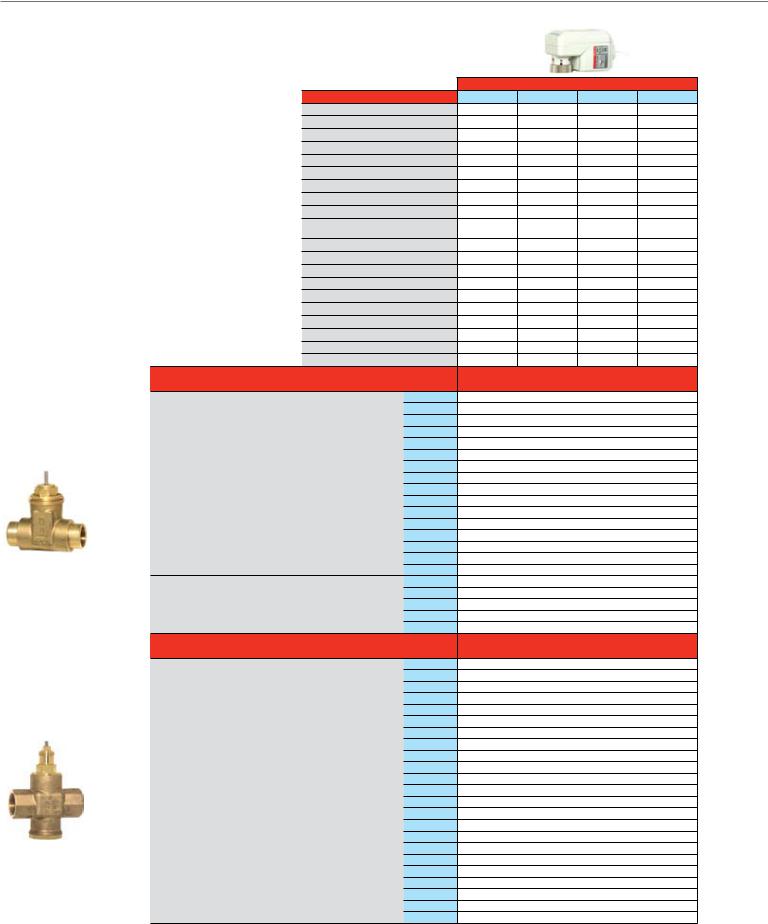
Cartridge Globe Valves
For more than 50 years, Honeywell has manufactured the V58 series of premium Cartridge Globe Valves. The compact size and replacement capabilities make it a great choice for controlling modulating unitary equipment.
|
|
|
|
Actuator O.S. Number |
|||||
Valves 1" and larger feature a pressure balanced design |
Power Supply |
|
|
|
Voltage |
||||
with enhanced close-off (levels). |
|
|
|
|
|
|
|
Frequency |
|
|
|
|
|
|
|
|
Power |
||
|
|
|
|
|
|
|
|
|
|
Common Features |
|
|
|
|
|
|
|
Stem Force (lb.) |
|
|
|
Control |
|
|
2-Position SPDT |
||||
• Maximum static pressure 235 psi |
|
|
|
|
|
|
|
Floating |
|
|
|
|
|
|
|
|
0(2)-10 Vdc |
||
• Long stroke allows for a wide range of control |
|
|
|
|
|
|
|||
|
4-20 mA (external 500 Ohm resistor) |
||||||||
• Leakage rate: 0.02% of Cv |
|
|
|
|
|
Pneumatic Spring Range |
|||
• Insert replacement tool allows for the valve cartridge |
Fail Safe Action |
|
|
|
|
||||
|
|
|
|
|
|
||||
to be replaced or changed without draining the system |
Reversible Operation |
|
Wiring Change |
||||||
(½" and ¾" models only) |
|
|
|
|
|
|
|
DIP Switch |
|
|
|
Stroke Timing |
|
Seconds @ 60 Hz (Drive) |
|||||
• Brass body and stainless steel stem |
|
|
|||||||
|
|
|
|
|
|
Fail Safe |
|||
• Threaded plastic valve cover/manual handle allows |
Manual Override |
(Use valve dust cap) |
|||||||
for manual operation |
|
|
Position Indicator |
|
|
||||
• Corrosion resistant |
|
|
Electrical Connection |
Cable length, in. |
|||||
|
|
|
|
|
Plenum-rated Cable |
||||
|
|
|
|
|
|
|
|||
|
|
|
|
|
|
|
|
Screw terminals |
|
|
|
|
|
|
|
|
1/2 in. flexible conduit hub |
||
|
Valve Size |
Pipe |
Flow |
Flow |
|
|
Valve |
|
Valve O.S. |
|
(inches) |
Connection Type |
Capacity (Cv) |
Characteristic |
|
|
Closes |
|
Number |
|
|
f NPT |
0.19 |
|
|
|
|
|
V5862A2005 |
|
|
Sweat |
0.19 |
|
|
|
|
|
V5852A2007 |
|
|
f NPT |
0.29 |
|
|
|
|
|
V5862A2013 |
|
|
Sweat |
0.29 |
|
|
|
|
|
V5852A2015 |
|
|
f NPT |
0.47 |
|
|
|
|
|
V5862A2021 |
|
1/2" |
Sweat |
0.47 |
|
|
|
|
|
V5852A2023 |
|
f NPT |
0.74 |
|
|
|
|
|
V5862A2039 |
|
|
|
|
|
|
|
|
|||
|
|
Sweat |
0.74 |
Equal% |
|
Stem Down2 |
|
V5852A2031 |
|
Way |
|
f NPT |
1.2 |
|
|
V5862A2047 |
|||
|
|
|
|
|
|
||||
|
Sweat |
1.2 |
|
|
|
|
|
V5852A2049 |
|
|
f NPT |
1.9 |
|
|
|
|
|
V5862A2054 |
|
2- |
|
Sweat |
1.9 |
|
|
|
|
|
V5852A2056 |
|
|
f NPT |
2.9 |
|
|
|
|
|
V5862A2062 |
|
3/4" |
Sweat |
2.9 |
|
|
|
|
|
V5852A2064 |
|
f NPT |
4.9 |
|
|
|
|
|
V5862A2070 |
|
|
|
|
|
|
|
|
|||
|
|
Sweat |
4.9 |
|
|
|
|
|
V5852A2072 |
|
|
f NPT |
5.5 |
|
|
|
|
|
V5862A3003 |
|
1" |
f NPT |
7.8 |
|
|
|
|
|
V5862A3011 |
|
|
f NPT |
11 |
Linear |
|
|
Stem Up |
|
V5862A3029 |
|
1-1/4" |
f NPT |
18 |
|
|
|
|
|
V5862A3037 |
|
1-1/2" |
f NPT |
25 |
|
|
|
|
|
V5862A3045 |
|
Valve Size |
Pipe |
Flow |
Flow |
|
|
Valve |
|
Valve O.S. |
|
(inches) |
Connection Type |
Capacity (Cv) |
Characteristic |
|
|
Closes |
|
Number |
|
|
f NPT |
0.29 |
|
|
|
|
|
V5863A2004 |
|
|
Sweat |
0.29 |
|
|
|
|
|
V5853A2006 |
|
|
f NPT |
0.47 |
|
|
|
|
|
V5863A2012 |
|
|
Sweat |
0.47 |
|
|
|
|
|
V5853A2014 |
|
1/2" |
f NPT |
0.74 |
|
|
|
|
|
V5863A2020 |
|
Sweat |
0.74 |
|
|
|
|
|
V5853A2022 |
|
|
|
|
|
|
|
|
|||
|
|
f NPT |
1.2 |
|
|
|
|
|
V5863A2038 |
|
|
Sweat |
1.2 |
|
|
|
|
|
V5853A2030 |
|
|
f NPT |
1.9 |
A-AB Equal%, |
|
|
|
|
V5863A2046 |
Way |
|
Sweat |
1.9 |
B-AB Linear |
|
|
|
|
V5853A2048 |
|
f NPT |
2.9 |
|
|
|
|
|
V5863A1006 |
|
|
Sweat |
2.9 |
|
|
|
Stem Up |
|
V5853A1008 |
|
3- |
|
f NPT |
4.9 |
|
|
|
|
|
V5863A1014 |
|
3/4" |
Sweat |
4.9 |
|
|
|
|
|
V5853A1016 |
|
f NPT |
2.9 |
|
|
|
|
|
V5863A2053 |
|
|
|
|
|
|
|
|
|||
|
|
Sweat |
2.9 |
|
|
|
|
|
V5853A2055 |
|
|
f NPT |
4.9 |
|
|
|
|
|
V5863A2061 |
|
|
Sweat |
4.9 |
|
|
|
|
|
V5853A2063 |
|
|
f NPT |
5.5 |
|
|
|
|
|
V5863A3002 |
|
1" |
f NPT |
7.8 |
|
|
|
|
|
V5863A3010 |
|
|
f NPT |
11 |
Linear |
|
|
|
|
V5863A3028 |
|
1-1/4" |
f NPT |
18 |
|
|
|
|
|
V5863A3036 |
|
1-1/2" |
f NPT |
25 |
|
|
|
|
|
V5863A3044 |
Non-Fail Safe
M6410A1029 |
M6410A3017 |
M7410F1000 |
M7410F3006 |
24 Vac |
24 Vac |
24 Vac |
24 Vac |
50/60 Hz |
50/60 Hz |
50/60 Hz |
50/60 Hz |
0.7 VA |
0.7 VA |
1.4 VA |
1.4 VA |
40.5 |
67.5 |
40.5 |
67.5 |
••
••
|
|
DIP Switch |
DIP Switch |
|
|
• |
• |
Stay in Place |
Stay in Place |
Stay in Place |
Stay in Place |
••
|
|
• |
• |
125 |
125 |
125 |
125 |
• |
• |
• |
• |
• |
• |
• |
• |
36 |
36 |
36 |
36 |
• |
• |
• |
• |
• |
• |
• |
• |
|
Close-off Pressure, psid |
|
|
232 |
|
232 |
|
|
|
||
232 |
|
232 |
|
232 |
|
232 |
|
232 |
|
232 |
|
232 |
|
232 |
|
232 |
|
232 |
|
232 |
|
232 |
|
232 |
|
232 |
|
174 |
|
174 |
|
174 |
|
174 |
|
174 |
|
174 |
|
174 |
|
174 |
|
58 |
|
58 |
|
58 |
|
58 |
|
58 |
|
58 |
|
58 |
|
58 |
|
|
232 |
|
232 |
|
232 |
|
232 |
|
232 |
|
232 |
|
174 |
|
174 |
|
145 |
|
145 |
|
Close-off Pressure, psid |
|
|
116 |
|
|
|
|
116 |
|
|
116 |
|
116 |
|
116 |
|
116 |
|
116 |
|
116 |
|
36 |
|
36 |
|
36 |
|
36 |
|
36 |
|
36 |
|
36 |
|
36 |
|
34 |
|
34 |
|
34 |
|
34 |
|
34 |
|
34 |
|
34 |
|
34 |
|
34 |
|
34 |
|
34 |
|
34 |
|
7.25 |
|
7.25 |
|
7.25 |
|
7.25 |
|
7.25 |
|
7.25 |
|
7.25 |
|
7.25 |
|
|
232 |
|
232 |
|
232 |
|
232 |
|
232 |
|
232 |
|
174 |
|
174 |
|
145 |
|
145 |
|
Notes: Maximum coil-bypass pressure difference is 7 psi when used with electric actuators. |
|
26 |
1 |
B port Cv is 20% less |
2 |
Fail safe position for 1/2" and 3/4" 2-way is Normally Open with Mx435 and MP958 spring return actuators. All other valves fail safe closed. |
|
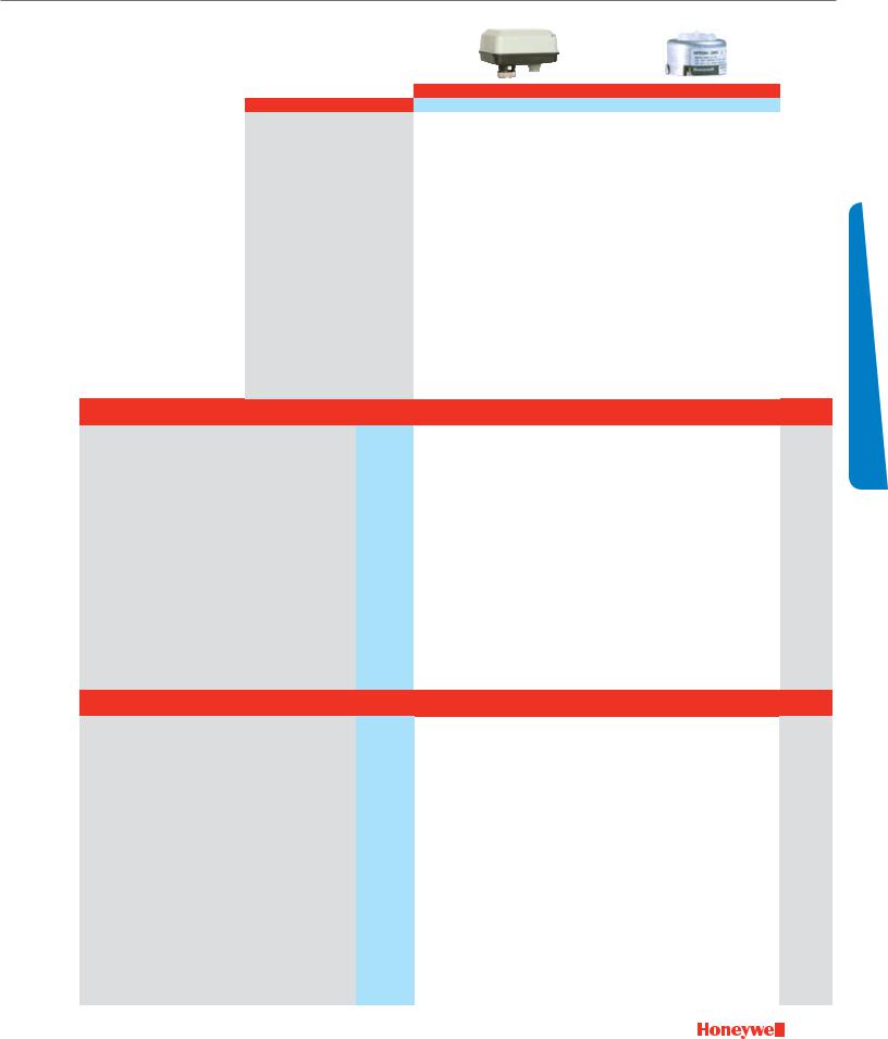
Cartridge Globe Valves
2-Way
3-Way
|
|
|
|
|
|
|
|
|
|
|
Fail Safe |
|
|
|
Pneumatic |
|
|
|||
|
|
|
Actuator O.S. Number |
M6435A1004 |
M6435A3000 |
M7435F1001 |
M7435F3007 |
MP958A1009 |
MP958A1017 |
MP958A1025 |
|
|||||||||
|
|
|
Power Supply |
|
|
|
Voltage |
24 Vac |
|
24 Vac |
24 Vac |
|
24 Vac |
|
|
|
|
|
|
|
|
|
|
|
|
|
|
|
Frequency |
50/60 Hz |
|
50/60 Hz |
50/60 Hz |
|
50/60 Hz |
|
|
|
|
|
|
|
|
|
|
|
|
|
|
Power |
10 VA |
|
10 VA |
5 VA |
|
5 VA |
|
|
|
|
|
|
|
|
|
|
|
|
|
|
Stem Force (lb.) |
40.5 |
|
90 |
40.5 |
|
90 |
|
|
|
|
|
|
|
|
|
Control |
|
|
2-Position SPDT |
• |
|
• |
|
|
|
|
|
|
|
|
|
||
|
|
|
|
|
|
|
|
Floating |
• |
|
• |
|
|
|
|
|
|
|
|
|
|
|
|
|
|
|
|
|
0(2)-10 Vdc |
|
|
|
DIP Switch |
|
DIP Switch |
|
|
|
|
|
|
|
|
|
4-20 mA (external 500 Ohm resistor) |
|
|
|
• |
|
• |
|
|
|
|
|
|
|||||
|
|
|
|
|
|
Pneumatic Spring Range |
|
|
|
|
|
|
2-5 psi |
|
3-10 psi |
|
8-11 psi |
|
||
|
|
|
Fail Safe Action |
|
|
|
|
2-way N.O. |
|
N.C. |
2-way N.O. |
|
N.C. |
2-way N.O. |
|
2-way N.O. |
|
2-way N.O. |
|
|
|
|
|
|
|
|
|
3-way N.C. |
|
3-way N.C. |
|
3-way N.C. |
|
3-way N.C. |
|
3-way N.C. |
|
||||
|
|
|
|
|
|
|
|
|
|
|
|
|
|
|
|
|||||
|
|
|
Reversible Operation |
|
Wiring Change |
• |
|
• |
|
|
|
|
|
|
|
|
|
|||
|
|
|
|
|
|
|
|
DIP Switch |
|
|
|
• |
|
• |
|
|
|
|
|
|
|
|
|
Stroke Timing |
|
Seconds @ 60 Hz (Drive) |
50 |
|
50 |
50 |
|
50 |
|
|
|
|
|
|
|||
|
|
|
|
|
|
|
|
Fail Safe |
10 |
|
10 |
10 |
|
10 |
|
|
|
|
|
|
|
|
|
Manual Override |
(Use valve dust cap) |
• |
|
• |
• |
|
• |
• |
|
• |
|
• |
|
||||
|
|
|
Position Indicator |
|
|
• |
|
• |
• |
|
• |
|
|
|
|
|
|
|||
|
|
|
Electrical Connection |
Cable length, in. |
|
|
|
|
|
|
|
|
|
|
|
|
||||
|
|
|
|
|
|
Plenum-rated Cable |
|
|
|
|
|
|
|
|
|
|
|
|
||
|
|
|
|
|
|
|
Screw terminals |
• |
|
• |
• |
|
• |
|
|
|
|
|
|
|
|
|
|
|
|
|
1/2 in. flexible conduit hub |
• |
|
• |
• |
|
• |
|
|
|
|
|
|
||
Valve Size |
Pipe |
Flow |
Flow |
|
|
Valve |
|
Valve O.S. |
|
Close-off Pressure, psid |
|
A-port Close-off Pressure, psid |
Replacement |
|||||||
(inches) |
Connection Type |
Capacity (Cv) |
Characteristic |
|
|
Closes |
|
Number |
|
|
|
Full air pressure* |
|
Insert3 |
||||||
|
f NPT |
0.19 |
|
|
|
|
|
V5862A2005 |
232 |
|
|
232 |
|
|
232 |
|
232 |
|
232 |
0902812 |
|
Sweat |
0.19 |
|
|
|
|
|
V5852A2007 |
232 |
|
|
232 |
|
|
232 |
|
232 |
|
232 |
0902812 |
|
f NPT |
0.29 |
|
|
|
|
|
V5862A2013 |
232 |
|
|
232 |
|
|
232 |
|
232 |
|
232 |
0902811 |
|
Sweat |
0.29 |
|
|
|
|
|
V5852A2015 |
232 |
|
|
232 |
|
|
232 |
|
232 |
|
232 |
0902811 |
|
f NPT |
0.47 |
|
|
|
|
|
V5862A2021 |
232 |
|
|
232 |
|
|
232 |
|
232 |
|
232 |
0902810 |
1/2" |
Sweat |
0.47 |
|
|
|
|
|
V5852A2023 |
232 |
|
|
232 |
|
|
232 |
|
232 |
|
232 |
0902810 |
f NPT |
0.74 |
|
|
|
|
|
V5862A2039 |
232 |
|
|
232 |
|
|
232 |
|
232 |
|
232 |
0902809 |
|
|
|
|
|
|
|
|
|
|
|
|
|
|||||||||
|
Sweat |
0.74 |
Equal% |
|
Stem Down2 |
|
V5852A2031 |
232 |
|
|
232 |
|
|
232 |
|
232 |
|
232 |
0902809 |
|
|
f NPT |
1.2 |
|
|
V5862A2047 |
174 |
|
|
174 |
|
|
232 |
|
140 |
|
120 |
0902808 |
|||
|
|
|
|
|
|
|
|
|
|
|
|
|||||||||
|
Sweat |
1.2 |
|
|
|
|
|
V5852A2049 |
174 |
|
|
174 |
|
|
232 |
|
140 |
|
120 |
0902808 |
|
f NPT |
1.9 |
|
|
|
|
|
V5862A2054 |
174 |
|
|
174 |
|
|
232 |
|
140 |
|
120 |
0902807 |
|
Sweat |
1.9 |
|
|
|
|
|
V5852A2056 |
174 |
|
|
174 |
|
|
232 |
|
140 |
|
120 |
0902807 |
|
f NPT |
2.9 |
|
|
|
|
|
V5862A2062 |
58 |
|
|
58 |
|
|
90 |
|
50 |
|
40 |
0902814 |
3/4" |
Sweat |
2.9 |
|
|
|
|
|
V5852A2064 |
58 |
|
|
58 |
|
|
90 |
|
50 |
|
40 |
0902814 |
f NPT |
4.9 |
|
|
|
|
|
V5862A2070 |
58 |
|
|
58 |
|
|
90 |
|
50 |
|
40 |
0902815 |
|
|
|
|
|
|
|
|
|
|
|
|
|
|||||||||
|
Sweat |
4.9 |
|
|
|
|
|
V5852A2072 |
58 |
|
|
58 |
|
|
90 |
|
50 |
|
40 |
0902815 |
|
f NPT |
5.5 |
|
|
|
|
|
V5862A3003 |
|
|
232 |
|
|
232 |
|
|
|
|
|
0903827 |
1" |
f NPT |
7.8 |
|
|
|
|
|
V5862A3011 |
|
|
232 |
|
|
232 |
|
|
|
|
|
0903827 |
|
f NPT |
11 |
Linear |
|
|
Stem Up |
|
V5862A3029 |
|
|
232 |
|
|
232 |
|
|
|
|
|
0903827 |
1-1/4" |
f NPT |
18 |
|
|
|
|
|
V5862A3037 |
|
|
174 |
|
|
174 |
|
|
|
|
|
0903828 |
1-1/2" |
f NPT |
25 |
|
|
|
|
|
V5862A3045 |
|
|
145 |
|
|
145 |
|
|
|
|
|
0903829 |
Valve Size |
Pipe |
Flow |
Flow |
|
|
Valve |
|
Valve O.S. |
|
Close-off Pressure, psid |
|
A-port Close-off Pressure, psid |
Replacement |
|||||||
(inches) |
Connection Type |
Capacity (Cv) |
Characteristic |
|
|
Closes |
|
Number |
|
|
|
Full air pressure* |
|
Insert3 |
||||||
|
f NPT |
0.29 |
|
|
|
|
|
V5863A2004 |
116 |
|
|
116 |
|
|
20 |
|
80 |
|
232 |
0902821 |
|
Sweat |
0.29 |
|
|
|
|
|
V5853A2006 |
116 |
|
|
116 |
|
|
20 |
|
80 |
|
232 |
0902821 |
|
f NPT |
0.47 |
|
|
|
|
|
V5863A2012 |
116 |
|
|
116 |
|
|
20 |
|
80 |
|
232 |
0902822 |
|
Sweat |
0.47 |
|
|
|
|
|
V5853A2014 |
116 |
|
|
116 |
|
|
20 |
|
80 |
|
232 |
0902822 |
1/2" |
f NPT |
0.74 |
|
|
|
|
|
V5863A2020 |
36 |
|
|
36 |
|
|
20 |
|
80 |
|
232 |
0902823 |
Sweat |
0.74 |
|
|
|
|
|
V5853A2022 |
36 |
|
|
36 |
|
|
20 |
|
80 |
|
232 |
0902823 |
|
|
|
|
|
|
|
|
|
|
|
|
|
|||||||||
|
f NPT |
1.2 |
|
|
|
|
|
V5863A2038 |
36 |
|
|
36 |
|
|
N / A |
|
10 |
|
100 |
0902824 |
|
Sweat |
1.2 |
|
|
|
|
|
V5853A2030 |
36 |
|
|
36 |
|
|
N / A |
|
10 |
|
100 |
0902824 |
|
f NPT |
1.9 |
A-AB Equal%, |
|
|
|
|
V5863A2046 |
34 |
|
|
34 |
|
|
N / A |
|
10 |
|
100 |
0902825 |
|
Sweat |
1.9 |
B-AB Linear |
|
|
|
|
V5853A2048 |
34 |
|
|
34 |
|
|
N / A |
|
10 |
|
100 |
0902825 |
|
f NPT |
2.9 |
|
|
|
|
|
V5863A1006 |
34 |
|
|
34 |
|
|
|
|
|
|
|
0902826 |
|
Sweat |
2.9 |
|
|
|
Stem Up |
|
V5853A1008 |
34 |
|
|
34 |
|
|
|
|
|
|
|
0902826 |
|
f NPT |
4.9 |
|
|
|
|
|
V5863A1014 |
34 |
|
|
34 |
|
|
|
|
|
|
|
0902827 |
3/4" |
Sweat |
4.9 |
|
|
|
|
|
V5853A1016 |
34 |
|
|
34 |
|
|
|
|
|
|
|
0902827 |
f NPT |
2.9 |
|
|
|
|
|
V5863A2053 |
7.25 |
|
|
7.25 |
|
|
N / A |
|
N / A |
|
35 |
0902818 |
|
|
|
|
|
|
|
|
|
|
|
|
|
|||||||||
|
Sweat |
2.9 |
|
|
|
|
|
V5853A2055 |
7.25 |
|
|
7.25 |
|
|
N / A |
|
N / A |
|
35 |
0902818 |
|
f NPT |
4.9 |
|
|
|
|
|
V5863A2061 |
7.25 |
|
|
7.25 |
|
|
N / A |
|
N / A |
|
35 |
0902819 |
|
Sweat |
4.9 |
|
|
|
|
|
V5853A2063 |
7.25 |
|
|
7.25 |
|
|
N / A |
|
N / A |
|
35 |
0902819 |
|
f NPT |
5.5 |
|
|
|
|
|
V5863A3002 |
|
|
232 |
|
|
232 |
|
|
|
|
|
0903827 |
1" |
f NPT |
7.8 |
|
|
|
|
|
V5863A3010 |
|
|
232 |
|
|
232 |
|
|
|
|
|
0903827 |
|
f NPT |
11 |
Linear |
|
|
|
|
V5863A3028 |
|
|
232 |
|
|
232 |
|
|
|
|
|
0903827 |
1-1/4" |
f NPT |
18 |
|
|
|
|
|
V5863A3036 |
|
|
174 |
|
|
174 |
|
|
|
|
|
0903828 |
1-1/2" |
f NPT |
25 |
|
|
|
|
|
V5863A3044 |
|
|
145 |
|
|
145 |
|
|
|
|
|
0903829 |
Selection Valve
Notes: *20 psi for 2-way; 0 psi for 3-way |
|
B-port Close-off of 3-way valves is the same as A-port in 2-way valves |
27 |
3 Insert determines Cv for 1/2” and 3/4" bodies. Grouped inserts are interchangeable. |

Control Ball Valves ½- 3"
2-Way NPT NEMA 2
Honeywell's Control Ball Valve product lines (VBN and VBF) feature the largest Cv range in the industry. A patented seat design allows for lower torque actuators, while a single spring return actuator may be used for up to a 70 psid differential pressure close-off on up to a 6" connection size.
The VBN family features a unique field replaceable stem assembly.
Common Features
•Max static pressure 360 psi (250°F)
•Medium: Water/glycol solutions up to 50%.
•Temperature range: -22 to +250°F
•Field configurable open or closed fail-safe position
•ANSI class IV leakage (0.01% of Cv)
VBN2 (Two-way)
•Equal % flow insert. Linear with full port. (Largest Cv valve in each valve size is full port), as noted
•Nickel-chrome plated brass or 316 stainless steel ball and stem
2-Way
NEED TO
PHOTOSHOP
|
Actuator Features |
|
|
Non-fail Safe |
|
||
|
|
|
|
|
|
|
|
|
Actuator O.S. Number |
MN6105A1011 |
MN6105A1011 |
MN7505A2001 |
MN7505A2001 |
||
|
|
|
|
|
|
|
|
|
Power Supply |
Voltage |
24 Vac |
24 Vac |
24 Vac |
24 Vac |
|
|
|
|
Frequency |
50 / 60 Hz |
50 / 60 Hz |
50 / 60 Hz |
50 / 60 Hz |
|
|
|
Power |
5 VA |
5 VA |
5 VA |
5 VA |
|
Actuator Torque |
(lb.-in.) |
44 |
44 |
44 |
44 |
|
|
Control |
(0)2-10 Vdc |
|
|
• |
• |
|
|
4-20 mA (external 500 Ohm Resistor) |
|
|
• |
• |
||
|
|
|
Floating |
• |
• |
• |
• |
|
|
|
Two-Position SPDT |
• |
• |
• |
• |
|
|
|
Two-Position SPST |
|
|
• |
• |
|
Fail Safe Action |
|
Stay in Place |
Stay in Place |
Stay in Place |
Stay in Place |
|
|
Normal Position (no signal) |
Closed |
Closed |
Closed |
Closed |
||
|
Actuator Stroke |
(degrees) |
95° ± 3° |
95° ± 3° |
95° ± 3° |
95° ± 3° |
|
|
Timing |
(seconds) |
90 |
90 |
90 |
90 |
|
|
Aux Switch |
2 x SPDT Add-on |
SSW2 |
SSW2 |
SW2-US |
SW2-US |
|
|
Feedback |
2-10 Vdc Built In |
- |
- |
• |
• |
|
|
Valve Features |
Trim |
Nickel-Plated Brass |
Stainless Steel |
Nickel-Plated Brass |
Stainless Steel |
|
Valve Size |
Cv |
|
Close-off |
|
Valve O.S. Number |
|
|
(inches) |
|
Differential Pressure (psi) |
|
|
|||
|
|
|
|
|
|
||
|
0.38 |
|
|
vbn2ab3P0a |
vbn2ab3s0a |
vbn2ab3P0b |
vbn2ab3s0b |
|
0.68 |
|
|
vbn2ad3P0a |
vbn2ad3s0a |
vbn2ad3P0b |
vbn2ad3s0b |
|
1.3 |
|
|
vbn2ae3P0a |
vbn2ae3s0a |
vbn2ae3P0b |
vbn2ae3s0b |
1/2" |
2 |
|
|
vbn2aF3P0a |
vbn2aF3s0a |
vbn2aF3P0b |
vbn2aF3s0b |
2.6 |
|
|
vbn2ag3P0a |
vbn2ag3s0a |
vbn2ag3P0b |
vbn2ag3s0b |
|
|
|
|
|||||
|
4.7 |
|
|
vbn2aH3P0a |
vbn2aH3s0a |
vbn2aH3P0b |
vbn2aH3s0b |
|
8 |
|
|
vbn2aJ3P0a |
vbn2aJ3s0a |
vbn2aJ3P0b |
vbn2aJ3s0b |
|
11.7* |
|
|
vbn2ak3P0a |
vbn2ak3s0a |
vbn2ak3P0b |
vbn2ak3s0b |
|
0.31 |
|
130 |
vbn2bb3P0a |
vbn2bb3s0a |
vbn2bb3P0b |
vbn2bb3s0b |
|
0.63 |
|
|
vbn2bd3P0a |
vbn2bd3s0a |
vbn2bd3P0b |
vbn2bd3s0b |
|
1.2 |
|
|
vbn2be3P0a |
vbn2be3s0a |
vbn2be3P0b |
vbn2be3s0b |
|
2.5 |
|
|
vbn2bg3P0a |
vbn2bg3s0a |
vbn2bg3P0b |
vbn2bg3s0b |
3/4" |
4.3 |
|
|
vbn2bH3P0a |
vbn2bH3s0a |
vbn2bH3P0b |
vbn2bH3s0b |
|
7.4 |
|
|
vbn2bJ3P0a |
vbn2bJ3s0a |
vbn2bJ3P0b |
vbn2bJ3s0b |
|
10.1 |
|
|
vbn2bk3P0a |
vbn2bk3s0a |
vbn2bk3P0b |
vbn2bk3s0b |
|
14.7* |
|
|
vbn2bl3P0a |
vbn2bl3s0a |
vbn2bl3P0b |
vbn2bl3s0b |
|
29* |
|
|
vbn2bM3P0a |
vbn2bM3s0a |
vbn2bM3P0b |
vbn2bM3s0b |
|
4.4 |
|
|
vbn2CH3P0a |
vbn2CH3s0a |
vbn2CH3P0b |
vbn2CH3s0b |
|
9 |
|
|
vbn2CJ3P0a |
vbn2CJ3s0a |
vbn2CJ3P0b |
vbn2CJ3s0b |
1" |
15.3 |
|
|
vbn2Cl3P0a |
vbn2Cl3s0a |
vbn2Cl3P0b |
vbn2Cl3s0b |
26 |
|
|
vbn2CM3P0a |
vbn2CM3s0a |
vbn2CM3P0b |
vbn2CM3s0b |
|
|
|
|
|||||
|
44* |
|
|
vbn2Cn3P0a |
vbn2Cn3s0a |
vbn2Cn3P0b |
vbn2Cn3s0b |
|
54* |
|
|
vbn2CP3P0a |
vbn2CP3s0a |
vbn2CP3P0b |
vbn2CP3s0b |
|
4.4 |
|
|
vbn2dH3P0a |
vbn2dH3s0a |
vbn2dH3P0b |
vbn2dH3s0b |
|
8.3 |
|
|
vbn2dJ3P0a |
vbn2dJ3s0a |
vbn2dJ3P0b |
vbn2dJ3s0b |
|
14.9 |
|
|
vbn2dk3P0a |
vbn2dk3s0a |
vbn2dk3P0b |
vbn2dk3s0b |
1-1/4" |
25 |
|
|
vbn2dl3P0a |
vbn2dl3s0a |
vbn2dl3P0b |
vbn2dl3s0b |
|
37 |
|
|
vbn2dM3P0a |
vbn2dM3s0a |
vbn2dM3P0b |
vbn2dM3s0b |
|
41* |
|
|
vbn2dn3P0a |
vbn2dn3s0a |
vbn2dn3P0b |
vbn2dn3s0b |
|
102* |
|
|
vbn2ds3P0a |
vbn2ds3s0a |
vbn2ds3P0b |
vbn2ds3s0b |
|
23 |
|
|
vbn2el3P0a |
vbn2el3s0a |
vbn2el3P0b |
vbn2el3s0b |
|
30 |
|
|
vbn2eM3P0a |
vbn2eM3s0a |
vbn2eM3P0b |
vbn2eM3s0b |
1-1/2" |
41 |
|
|
vbn2en3P0a |
vbn2en3s0a |
vbn2en3P0b |
vbn2en3s0b |
|
74* |
|
|
vbn2er3P0a |
vbn2er3s0a |
vbn2er3P0b |
vbn2er3s0b |
|
172* |
|
100 |
vbn2e13P0a |
vbn2e13s0a |
vbn2e13P0b |
vbn2e13s0b |
|
42 |
|
vbn2Fn3P0a |
vbn2Fn3s0a |
vbn2Fn3P0b |
vbn2Fn3s0b |
|
|
|
|
|||||
|
57 |
|
|
vbn2FP3P0a |
vbn2FP3s0a |
vbn2FP3P0b |
vbn2FP3s0b |
|
71 |
|
|
vbn2Fr3P0a |
vbn2Fr3s0a |
vbn2Fr3P0b |
vbn2Fr3s0b |
2" |
100 |
|
|
vbn2Fs3P0a |
vbn2Fs3s0a |
vbn2Fs3P0b |
vbn2Fs3s0b |
|
108* |
|
|
vbn2Ft3P0a |
vbn2Ft3s0a |
vbn2Ft3P0b |
vbn2Ft3s0b |
|
210 |
|
|
vbn2F13P0a |
vbn2F13s0a |
vbn2F13P0b |
vbn2F13s0b |
|
266* |
|
|
vbn2F23P0a |
vbn2F23s0a |
vbn2F23P0b |
vbn2F23s0b |
|
45 |
|
|
vbn2gn3P0a |
vbn2gn3s0a |
vbn2gn3P0b |
vbn2gn3s0b |
|
55 |
|
|
vbn2gP3P0a |
vbn2gP3s0a |
vbn2gP3P0b |
vbn2gP3s0b |
2-1/2" |
72 |
|
|
vbn2gr3P0a |
vbn2gr3s0a |
vbn2gr3P0b |
vbn2gr3s0b |
101 |
|
|
vbn2gs3P0a |
vbn2gs3s0a |
vbn2gs3P0b |
vbn2gs3s0b |
|
|
|
|
|||||
|
162 |
|
|
vbn2gu3P0a |
vbn2gu3s0a |
vbn2gu3P0b |
vbn2gu3s0b |
|
202* |
|
|
vbn2g13P0a |
vbn2g13s0a |
vbn2g13P0b |
vbn2g13s0b |
|
49 |
|
|
vbn2Hn3P0a |
vbn2Hn3s0a |
vbn2Hn3P0b |
vbn2Hn3s0b |
|
63 |
|
|
vbn2HP3P0a |
vbn2HP3s0a |
vbn2HP3P0b |
vbn2HP3s0b |
3" |
82 |
|
|
vbn2Hr3P0a |
vbn2Hr3s0a |
vbn2Hr3P0b |
vbn2Hr3s0b |
|
124 |
|
|
vbn2Ht3P0a |
vbn2Ht3s0a |
vbn2Ht3P0b |
vbn2Ht3s0b |
|
145* |
|
|
vbn2Hu3P0a |
vbn2Hu3s0a |
vbn2Hu3P0b |
vbn2Hu3s0b |
Full port ball. No flow characterizing insert.
28
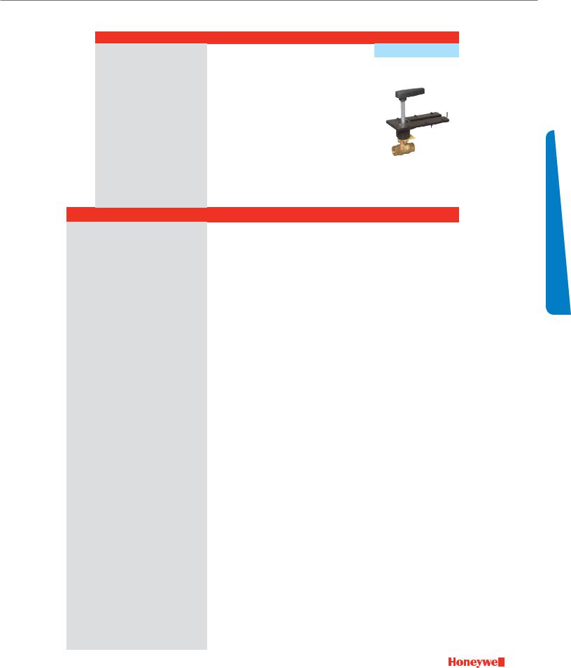
Control Ball Valves ½- 3"
2-Way NPT NEMA 2
|
|
Actuator Features |
|
|
Fail Safe |
|
|
|
||
|
|
|
|
|
|
|
|
|
|
|
|
|
Actuator O.S. Number |
MS8105A1030 |
MS8105A1030 |
MS7505A2030 |
MS7505A2030 |
Valve Only |
Valve Only |
||
|
|
|
|
|
|
|
|
|
|
|
|
|
Power Supply |
Voltage |
24 Vac |
24 Vac |
24 Vac |
24 Vac |
|
|
|
|
|
|
|
Frequency |
50 / 60 Hz |
50 / 60 Hz |
50 / 60 Hz |
50 / 60 Hz |
|
|
|
|
|
|
Power |
8VA |
8VA |
7.5 VA |
7.5 VA |
|
|
|
|
Actuator Torque |
(lb.-in.) |
44 |
44 |
44 |
44 |
|
|
|
|
|
Control |
(0)2-10 Vdc |
|
|
• |
• |
|
|
|
|
|
4-20 mA (external 500 Ohm Resistor) |
|
|
• |
• |
|
|
||
|
|
|
|
Floating |
|
|
• |
• |
|
|
|
|
|
|
Two-Position SPDT |
|
|
• |
• |
|
|
|
|
|
|
Two-Position SPST |
• |
• |
• |
• |
|
|
|
|
Fail Safe Action |
|
Closed* |
Closed* |
Closed* |
Closed* |
|
|
|
|
|
Normal Position (no signal) |
Closed* |
Closed* |
Closed* |
Closed* |
|
|
||
|
|
Actuator Stroke |
(degrees) |
95° ± 3° |
95° ± 3° |
95° ± 3° |
95° ± 3° |
|
|
|
|
|
Timing |
(seconds) |
45 |
45 |
90 |
90 |
|
|
|
|
|
Aux Switch |
2 x SPDT Add-on |
|
|
|
|
|
|
|
|
|
Feedback |
2-10 Vdc Built In |
|
|
• |
• |
|
|
|
|
|
Valve Features |
Trim |
Nickel-Plated Brass |
Stainless Steel |
Nickel-Plated Brass |
Stainless Steel |
Nickel-Plated Brass |
Stainless Steel |
|
|
Valve Size |
Cv |
|
Close-off |
|
|
Valve O.S. Number |
|
|
|
|
(inches) |
|
Differential Pressure (psi) |
|
|
|
|
|||
|
|
|
|
|
|
|
|
|
||
|
|
0.38 |
|
|
vbn2ab3P0C |
vbn2ab3s0C |
vbn2ab3P0d |
vbn2ab3s0d |
vbn2ab3P0X |
vbn2ab3s0X |
|
|
0.68 |
|
|
vbn2ad3P0C |
vbn2ad3s0C |
vbn2ad3P0d |
vbn2ad3s0d |
vbn2ad3P0X |
vbn2ad3s0X |
|
|
1.3 |
|
|
vbn2ae3P0C |
vbn2ae3s0C |
vbn2ae3P0d |
vbn2ae3s0d |
vbn2ae3P0X |
vbn2ae3s0X |
|
1/2" |
2 |
|
|
vbn2aF3P0C |
vbn2aF3s0C |
vbn2aF3P0d |
vbn2aF3s0d |
vbn2aF3P0X |
vbn2aF3s0X |
|
2.6 |
|
|
vbn2ag3P0C |
vbn2ag3s0C |
vbn2ag3P0d |
vbn2ag3s0d |
vbn2ag3P0X |
vbn2ag3s0X |
|
|
|
|
|
|||||||
|
|
4.7 |
|
|
vbn2aH3P0C |
vbn2aH3s0C |
vbn2aH3P0d |
vbn2aH3s0d |
vbn2aH3P0X |
vbn2aH3s0X |
|
|
8 |
|
|
vbn2aJ3P0C |
vbn2aJ3s0C |
vbn2aJ3P0d |
vbn2aJ3s0d |
vbn2aJ3P0X |
vbn2aJ3s0X |
|
|
11.7* |
|
|
vbn2ak3P0C |
vbn2ak3s0C |
vbn2ak3P0d |
vbn2ak3s0d |
vbn2ak3P0X |
vbn2ak3s0X |
|
|
0.31 |
|
130 |
vbn2bb3P0C |
vbn2bb3s0C |
vbn2bb3P0d |
vbn2bb3s0d |
vbn2bb3P0X |
vbn2bb3s0X |
|
|
0.63 |
|
|
vbn2bd3P0C |
vbn2bd3s0C |
vbn2bd3P0d |
vbn2bd3s0d |
vbn2bd3P0X |
vbn2bd3s0X |
|
|
1.2 |
|
|
vbn2be3P0C |
vbn2be3s0C |
vbn2be3P0d |
vbn2be3s0d |
vbn2be3P0X |
vbn2be3s0X |
|
|
2.5 |
|
|
vbn2bg3P0C |
vbn2bg3s0C |
vbn2bg3P0d |
vbn2bg3s0d |
vbn2bg3P0X |
vbn2bg3s0X |
|
3/4" |
4.3 |
|
|
vbn2bH3P0C |
vbn2bH3s0C |
vbn2bH3P0d |
vbn2bH3s0d |
vbn2bH3P0X |
vbn2bH3s0X |
|
|
7.4 |
|
|
vbn2bJ3P0C |
vbn2bJ3s0C |
vbn2bJ3P0d |
vbn2bJ3s0d |
vbn2bJ3P0X |
vbn2bJ3s0X |
|
|
10.1 |
|
|
vbn2bk3P0C |
vbn2bk3s0C |
vbn2bk3P0d |
vbn2bk3s0d |
vbn2bk3P0X |
vbn2bk3s0X |
|
|
14.7* |
|
|
vbn2bl3P0C |
vbn2bl3s0C |
vbn2bl3P0d |
vbn2bl3s0d |
vbn2bl3P0X |
vbn2bl3s0X |
|
|
29* |
|
|
vbn2bM3P0C |
vbn2bM3s0C |
vbn2bM3P0d |
vbn2bM3s0d |
vbn2bM3P0X |
vbn2bM3s0X |
|
|
4.4 |
|
|
vbn2CH3P0C |
vbn2CH3s0C |
vbn2CH3P0d |
vbn2CH3s0d |
vbn2CH3P0X |
vbn2CH3s0X |
|
|
9 |
|
|
vbn2CJ3P0C |
vbn2CJ3s0C |
vbn2CJ3P0d |
vbn2CJ3s0d |
vbn2CJ3P0X |
vbn2CJ3s0X |
|
1" |
15.3 |
|
|
vbn2Cl3P0C |
vbn2Cl3s0C |
vbn2Cl3P0d |
vbn2Cl3s0d |
vbn2Cl3P0X |
vbn2Cl3s0X |
|
26 |
|
|
vbn2CM3P0C |
vbn2CM3s0C |
vbn2CM3P0d |
vbn2CM3s0d |
vbn2CM3P0X |
vbn2CM3s0X |
|
|
|
|
|
|||||||
|
|
44* |
|
|
vbn2Cn3P0C |
vbn2Cn3s0C |
vbn2Cn3P0d |
vbn2Cn3s0d |
vbn2Cn3P0X |
vbn2Cn3s0X |
|
|
54* |
|
|
vbn2CP3P0C |
vbn2CP3s0C |
vbn2CP3P0d |
vbn2CP3s0d |
vbn2CP3P0X |
vbn2CP3s0X |
|
|
4.4 |
|
|
vbn2dH3P0C |
vbn2dH3s0C |
vbn2dH3P0d |
vbn2dH3s0d |
vbn2dH3P0X |
vbn2dH3s0X |
Way |
|
8.3 |
|
|
vbn2dJ3P0C |
vbn2dJ3s0C |
vbn2dJ3P0d |
vbn2dJ3s0d |
vbn2dJ3P0X |
vbn2dJ3s0X |
|
14.9 |
|
|
vbn2dk3P0C |
vbn2dk3s0C |
vbn2dk3P0d |
vbn2dk3s0d |
vbn2dk3P0X |
vbn2dk3s0X |
|
1-1/4" |
25 |
|
|
vbn2dl3P0C |
vbn2dl3s0C |
vbn2dl3P0d |
vbn2dl3s0d |
vbn2dl3P0X |
vbn2dl3s0X |
|
2- |
|
37 |
|
|
vbn2dM3P0C |
vbn2dM3s0C |
vbn2dM3P0d |
vbn2dM3s0d |
vbn2dM3P0X |
vbn2dM3s0X |
|
|
41* |
|
|
vbn2dn3P0C |
vbn2dn3s0C |
vbn2dn3P0d |
vbn2dn3s0d |
vbn2dn3P0X |
vbn2dn3s0X |
|
|
102* |
|
|
vbn2ds3P0C |
vbn2ds3s0C |
vbn2ds3P0d |
vbn2ds3s0d |
vbn2ds3P0X |
vbn2ds3s0X |
|
|
23 |
|
|
vbn2el3P0C |
vbn2el3s0C |
vbn2el3P0d |
vbn2el3s0d |
vbn2el3P0X |
vbn2el3s0X |
|
|
30 |
|
|
vbn2eM3P0C |
vbn2eM3s0C |
vbn2eM3P0d |
vbn2eM3s0d |
vbn2eM3P0X |
vbn2eM3s0X |
|
1-1/2" |
41 |
|
|
vbn2en3P0C |
vbn2en3s0C |
vbn2en3P0d |
vbn2en3s0d |
vbn2en3P0X |
vbn2en3s0X |
|
|
74* |
|
|
vbn2er3P0C |
vbn2er3s0C |
vbn2er3P0d |
vbn2er3s0d |
vbn2er3P0X |
vbn2er3s0X |
|
|
172* |
|
100 |
vbn2e13P0C |
vbn2e13s0C |
vbn2e13P0d |
vbn2e13s0d |
vbn2e13P0X |
vbn2e13s0X |
|
|
42 |
|
vbn2Fn3P0C |
vbn2Fn3s0C |
vbn2Fn3P0d |
vbn2Fn3s0d |
vbn2Fn3P0X |
vbn2Fn3s0X |
|
|
|
|
|
|||||||
|
|
57 |
|
|
vbn2FP3P0C |
vbn2FP3s0C |
vbn2FP3P0d |
vbn2FP3s0d |
vbn2FP3P0X |
vbn2FP3s0X |
|
|
71 |
|
|
vbn2Fr3P0C |
vbn2Fr3s0C |
vbn2Fr3P0d |
vbn2Fr3s0d |
vbn2Fr3P0X |
vbn2Fr3s0X |
|
2" |
100 |
|
|
vbn2Fs3P0C |
vbn2Fs3s0C |
vbn2Fs3P0d |
vbn2Fs3s0d |
vbn2Fs3P0X |
vbn2Fs3s0X |
|
|
108* |
|
|
vbn2Ft3P0C |
vbn2Ft3s0C |
vbn2Ft3P0d |
vbn2Ft3s0d |
vbn2Ft3P0X |
vbn2Ft3s0X |
|
|
210 |
|
|
vbn2F13P0C |
vbn2F13s0C |
vbn2F13P0d |
vbn2F13s0d |
vbn2F13P0X |
vbn2F13s0X |
|
|
266* |
|
|
vbn2F23P0C |
vbn2F23s0C |
vbn2F23P0d |
vbn2F23s0d |
vbn2F23P0X |
vbn2F23s0X |
|
|
45 |
|
|
vbn2gn3P0C |
vbn2gn3s0C |
vbn2gn3P0d |
vbn2gn3s0d |
vbn2gn3P0X |
vbn2gn3s0X |
|
|
55 |
|
|
vbn2gP3P0C |
vbn2gP3s0C |
vbn2gP3P0d |
vbn2gP3s0d |
vbn2gP3P0X |
vbn2gP3s0X |
|
2-1/2" |
72 |
|
|
vbn2gr3P0C |
vbn2gr3s0C |
vbn2gr3P0d |
vbn2gr3s0d |
vbn2gr3P0X |
vbn2gr3s0X |
|
101 |
|
|
vbn2gs3P0C |
vbn2gs3s0C |
vbn2gs3P0d |
vbn2gs3s0d |
vbn2gs3P0X |
vbn2gs3s0X |
|
|
|
|
|
|||||||
|
|
162 |
|
|
vbn2gu3P0C |
vbn2gu3s0C |
vbn2gu3P0d |
vbn2gu3s0d |
vbn2gu3P0X |
vbn2gu3s0X |
|
|
202* |
|
|
vbn2g13P0C |
vbn2g13s0C |
vbn2g13P0d |
vbn2g13s0d |
vbn2g13P0X |
vbn2g13s0X |
|
|
49 |
|
|
vbn2Hn3P0C |
vbn2Hn3s0C |
vbn2Hn3P0d |
vbn2Hn3s0d |
vbn2Hn3P0X |
vbn2Hn3s0X |
|
|
63 |
|
|
vbn2HP3P0C |
vbn2HP3s0C |
vbn2HP3P0d |
vbn2HP3s0d |
vbn2HP3P0X |
vbn2HP3s0X |
|
3" |
82 |
|
|
vbn2Hr3P0C |
vbn2Hr3s0C |
vbn2Hr3P0d |
vbn2Hr3s0d |
vbn2Hr3P0X |
vbn2Hr3s0X |
|
|
124 |
|
|
vbn2Ht3P0C |
vbn2Ht3s0C |
vbn2Ht3P0d |
vbn2Ht3s0d |
vbn2Ht3P0X |
vbn2Ht3s0X |
|
|
145* |
|
|
vbn2Hu3P0C |
vbn2Hu3s0C |
vbn2Hu3P0d |
vbn2Hu3s0d |
vbn2Hu3P0X |
vbn2Hu3s0X |
Full port ball. No flow characterizing insert.
ve SValelec tio n
29
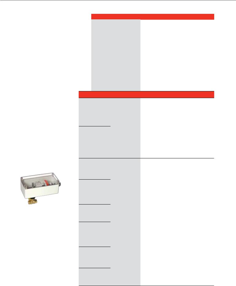
Control Ball Valves ½- 3"
2-Way NPT NEMA 3R
Common Features
•Max static pressure 360 psi (250°F)
•Medium: Water/glycol solutions up to 50%.
•Temperature range: -22 to +250°F
•Field configurable open or closed fail-safe position
•Removable handle for manual operation
•ANSI class IV leakage (0.01% of Cv)
VBN2 (Two-way):
•Equal % flow insert. Linear with full port. (Largest Cv valve in each valve size is full port)
•Nickel-chrome plated brass or 316 stainless steel ball and stem
Optional NEMA 3R enclosure
|
Valve Size |
|
(inches) |
|
1/2" |
|
3/4" |
|
1" |
Way |
1-1/4" |
2- |
|
|
1-1/2" |
|
2" |
|
2-1/2" |
|
3" |
|
|
Actuator Features |
|
|
|
Non-fail Safe |
|
||
|
|
|
|
|
|
|
|
Actuator O.S. Number |
|
MN6105A1011 |
MN6105A1011 |
MN7505A2001 |
MN7505A2001 |
||
|
|
|
|
|
|
|
|
Power Supply |
|
Voltage |
24 Vac |
24 Vac |
24 Vac |
24 Vac |
|
|
|
|
Frequency |
50 / 60 Hz |
50 / 60 Hz |
50 / 60 Hz |
50 / 60 Hz |
|
|
|
Power |
5 VA |
5 VA |
5 VA |
5 VA |
Actuator Torque |
|
(lb.-in.) |
44 |
44 |
44 |
44 |
|
Control |
|
(0)2-10 Vdc |
|
|
• |
• |
|
4-20 mA (external 500 Ohm Resistor) |
|
|
• |
• |
|||
|
|
|
Floating |
• |
• |
• |
• |
|
|
|
Two-Position SPDT |
• |
• |
• |
• |
|
|
|
Two-Position SPST |
|
|
• |
• |
Fail Safe Action |
|
|
Stay in Place |
Stay in Place |
Stay in Place |
Stay in Place |
|
Normal Position (no signal) |
|
Closed |
Closed |
Closed |
Closed |
||
Actuator Stroke |
|
(degrees) |
95° ± 3° |
95° ± 3° |
95° ± 3° |
95° ± 3° |
|
Timing |
|
(seconds) |
90 |
90 |
90 |
90 |
|
Aux Switch |
|
2 x SPDT Add-on |
SSW2 |
SSW2 |
SW2-US |
SW2-US |
|
Feedback |
|
2-10 Vdc Built In |
|
|
• |
• |
|
Valve Features |
|
|
Trim |
Nickel-Plated Brass |
Stainless Steel |
Nickel-Plated Brass |
Stainless Steel |
Cv |
|
|
Close-off |
|
Valve O.S. Number |
|
|
|
Differential Pressure (psi) |
|
|
||||
|
|
|
|
|
|
||
0.38 |
|
|
|
vbn2ab3PRa |
vbn2ab3sRa |
vbn2ab3PRb |
vbn2ab3sRb |
0.68 |
|
|
|
vbn2ad3PRa |
vbn2ad3sRa |
vbn2ad3PRb |
vbn2ad3sRb |
1.3 |
|
|
|
vbn2ae3PRa |
vbn2ae3sRa |
vbn2ae3PRb |
vbn2ae3sRb |
2 |
|
|
|
vbn2aF3PRa |
vbn2aF3sRa |
vbn2aF3PRb |
vbn2aF3sRb |
2.6 |
|
|
|
vbn2ag3PRa |
vbn2ag3sRa |
vbn2ag3PRb |
vbn2ag3sRb |
4.7 |
|
|
|
vbn2aH3PRa |
vbn2aH3sRa |
vbn2aH3PRb |
vbn2aH3sRb |
8 |
|
|
|
vbn2aJ3PRa |
vbn2aJ3sRa |
vbn2aJ3PRb |
vbn2aJ3sRb |
11.7* |
|
|
|
vbn2ak3PRa |
vbn2ak3sRa |
vbn2ak3PRb |
vbn2ak3sRb |
0.31 |
|
|
130 |
vbn2bb3PRa |
vbn2bb3sRa |
vbn2bb3PRb |
vbn2bb3sRb |
0.63 |
|
|
|
vbn2bd3PRa |
vbn2bd3sRa |
vbn2bd3PRb |
vbn2bd3sRb |
1.2 |
|
|
|
vbn2be3PRa |
vbn2be3sRa |
vbn2be3PRb |
vbn2be3sRb |
2.5 |
|
|
|
vbn2bg3PRa |
vbn2bg3sRa |
vbn2bg3PRb |
vbn2bg3sRb |
4.3 |
|
|
|
vbn2bH3PRa |
vbn2bH3sRa |
vbn2bH3PRb |
vbn2bH3sRb |
7.4 |
|
|
|
vbn2bJ3PRa |
vbn2bJ3sRa |
vbn2bJ3PRb |
vbn2bJ3sRb |
10.1 |
|
|
|
vbn2bk3PRa |
vbn2bk3sRa |
vbn2bk3PRb |
vbn2bk3sRb |
14.7* |
|
|
|
vbn2bl3PRa |
vbn2bl3sRa |
vbn2bl3PRb |
vbn2bl3sRb |
29* |
|
|
|
vbn2bM3PRa |
vbn2bM3sRa |
vbn2bM3PRb |
vbn2bM3sRb |
4.4 |
|
|
|
vbn2CH3PRa |
vbn2CH3sRa |
vbn2CH3PRb |
vbn2CH3sRb |
9 |
|
|
|
vbn2CJ3PRa |
vbn2CJ3sRa |
vbn2CJ3PRb |
vbn2CJ3sRb |
15.3 |
|
|
|
vbn2Cl3PRa |
vbn2Cl3sRa |
vbn2Cl3PRb |
vbn2Cl3sRb |
26 |
|
|
|
vbn2CM3PRa |
vbn2CM3sRa |
vbn2CM3PRb |
vbn2CM3sRb |
44* |
|
|
|
vbn2Cn3PRa |
vbn2Cn3sRa |
vbn2Cn3PRb |
vbn2Cn3sRb |
54* |
|
|
|
vbn2CP3PRa |
vbn2CP3sRa |
vbn2CP3PRb |
vbn2CP3sRb |
4.4 |
|
|
|
vbn2dH3PRa |
vbn2dH3sRa |
vbn2dH3PRb |
vbn2dH3sRb |
8.3 |
|
|
|
vbn2dJ3PRa |
vbn2dJ3sRa |
vbn2dJ3PRb |
vbn2dJ3sRb |
14.9 |
|
|
|
vbn2dk3PRa |
vbn2dk3sRa |
vbn2dk3PRb |
vbn2dk3sRb |
25 |
|
|
|
vbn2dl3PRa |
vbn2dl3sRa |
vbn2dl3PRb |
vbn2dl3sRb |
37 |
|
|
|
vbn2dM3PRa |
vbn2dM3sRa |
vbn2dM3PRb |
vbn2dM3sRb |
41* |
|
|
|
vbn2dn3PRa |
vbn2dn3sRa |
vbn2dn3PRb |
vbn2dn3sRb |
102* |
|
|
|
vbn2ds3PRa |
vbn2ds3sRa |
vbn2ds3PRb |
vbn2ds3sRb |
23 |
|
|
|
vbn2el3PRa |
vbn2el3sRa |
vbn2el3PRb |
vbn2el3sRb |
30 |
|
|
|
vbn2eM3PRa |
vbn2eM3sRa |
vbn2eM3PRb |
vbn2eM3sRb |
41 |
|
|
|
vbn2en3PRa |
vbn2en3sRa |
vbn2en3PRb |
vbn2en3sRb |
74* |
|
|
|
vbn2er3PRa |
vbn2er3sRa |
vbn2er3PRb |
vbn2er3sRb |
172* |
|
|
100 |
vbn2e13PRa |
vbn2e13sRa |
vbn2e13PRb |
vbn2e13sRb |
42 |
|
|
vbn2Fn3PRa |
vbn2Fn3sRa |
vbn2Fn3PRb |
vbn2Fn3sRb |
|
|
|
|
|||||
57 |
|
|
|
vbn2FP3PRa |
vbn2FP3sRa |
vbn2FP3PRb |
vbn2FP3sRb |
71 |
|
|
|
vbn2Fr3PRa |
vbn2Fr3sRa |
vbn2Fr3PRb |
vbn2Fr3sRb |
100 |
|
|
|
vbn2Fs3PRa |
vbn2Fs3sRa |
vbn2Fs3PRb |
vbn2Fs3sRb |
108* |
|
|
|
vbn2Ft3PRa |
vbn2Ft3sRa |
vbn2Ft3PRb |
vbn2Ft3sRb |
210 |
|
|
|
vbn2F13PRa |
vbn2F13sRa |
vbn2F13PRb |
vbn2F13sRb |
266* |
|
|
|
vbn2F23PRa |
vbn2F23sRa |
vbn2F23PRb |
vbn2F23sRb |
45 |
|
|
|
vbn2gn3PRa |
vbn2gn3sRa |
vbn2gn3PRb |
vbn2gn3sRb |
55 |
|
|
|
vbn2gP3PRa |
vbn2gP3sRa |
vbn2gP3PRb |
vbn2gP3sRb |
72 |
|
|
|
vbn2gr3PRa |
vbn2gr3sRa |
vbn2gr3PRb |
vbn2gr3sRb |
101 |
|
|
|
vbn2gs3PRa |
vbn2gs3sRa |
vbn2gs3PRb |
vbn2gs3sRb |
162 |
|
|
|
vbn2gu3PRa |
vbn2gu3sRa |
vbn2gu3PRb |
vbn2gu3sRb |
202* |
|
|
|
vbn2g13PRa |
vbn2g13sRa |
vbn2g13PRb |
vbn2g13sRb |
49 |
|
|
|
vbn2Hn3PRa |
vbn2Hn3sRa |
vbn2Hn3PRb |
vbn2Hn3sRb |
63 |
|
|
|
vbn2HP3PRa |
vbn2HP3sRa |
vbn2HP3PRb |
vbn2HP3sRb |
82 |
|
|
|
vbn2Hr3PRa |
vbn2Hr3sRa |
vbn2Hr3PRb |
vbn2Hr3sRb |
124 |
|
|
|
vbn2Ht3PRa |
vbn2Ht3sRa |
vbn2Ht3PRb |
vbn2Ht3sRb |
145* |
|
|
|
vbn2Hu3PRa |
vbn2Hu3sRa |
vbn2Hu3PRb |
vbn2Hu3sRb |
Full port ball. No flow characterizing insert.
30
 Loading...