


 Loading...
Perfect Climate Comfort Center™
Control System
PRODUCT DATA
PC8900A
W8900A-C
GENERAL
This document contains information on the Perfect Climate Comfort Center™ Control System including components and accessories. Some components and accessories include the PC8900A Control Panel, W8900A-C Remote Module, C7189A Remote Indoor Sensor, C7089A Outdoor Sensor, C7100A Discharge Air Sensor, CO2 Monitor, CM8900A Communication Module, and W8735B Telephone Access Module.
The Comfort Center control system provides 24 Vac energy saving control for a heating and cooling system, while providing reliable and precise temperature, ventilation and humidity control.
FEATURES
The PC8900A mounts in the living space and accurately measures and controls room temperature and humidity.
•Only four wires required for installation.
•Large, continuously lit LCD.
•Seven-day (auto copy) programming.
•Simultaneous display of heat and cool setpoints.
•Keyboard lockout protection available.
•No batteries required, indefinite program retention.
•Circulation fan setting improves indoor air quality.
•Field configurable for:
—Automatic or manual changeover.
—°F or °C display.
—12or 24-hour clock.
—Adaptive Intelligent Recovery™ control or conventional recovery.
—Humidity control in heating or cooling.
—Outdoor, remote, and discharge temperature sensors available.
—Fan overrun in cooling.
—Ventilation control.
The W8900A-C mounts near the equipment. The PC8900A, heating, cooling, ventilation and dehumidification equipment and all additional sensors are wired to the W8900A-C.
•Compatible with most 24 Vac Systems.
•Remote sensor, discharge sensor, outdoor sensor and CO2 monitor available.
•Optional remote communications available.
|
Contents |
General ............................................................................. |
1 |
Features ........................................................................... |
1 |
Specifications .................................................................... |
2 |
Ordering Information ........................................................ |
2 |
Installation ........................................................................ |
5 |
Wiring Diagrams ............................................................... |
9 |
W8900A,C Hookup Diagrams ....................................... |
9 |
W8900B Hookup Diagrams ........................................... |
14 |
W8900A,B,C Humidity Control Hookup Diagrams |
........ 18 |
Installer Setup ................................................................... |
24 |
Programming PC8900A .................................................... |
27 |
Checkout .......................................................................... |
33 |
Operation .......................................................................... |
34 |
Troubleshooting ................................................................ |
40 |
Glossary ........................................................................... |
44 |
® U.S. Registered Trademark |
|
Copyright © 2001 Honeywell • All Rights Reserved |
68-0173-3 |
|

SPECIFICATIONS
IMPORTANT
The specifications given in this publication do not include normal manufacturing tolerances; therefore, an individual unit might not exactly match the listed specifications. Also, this product is tested and calibrated under closely controlled conditions, and some minor differences in performance can be expected if those conditions are changed.
Models:
The PC8900A Comfort Center™ Control Panel mounts in the living space and accurately measures and controls room temperature and humidity. The W8900A-C Remote Module provides a wiring panel and switching for the Perfect Climate Comfort Center™ Control System. See Table 1.
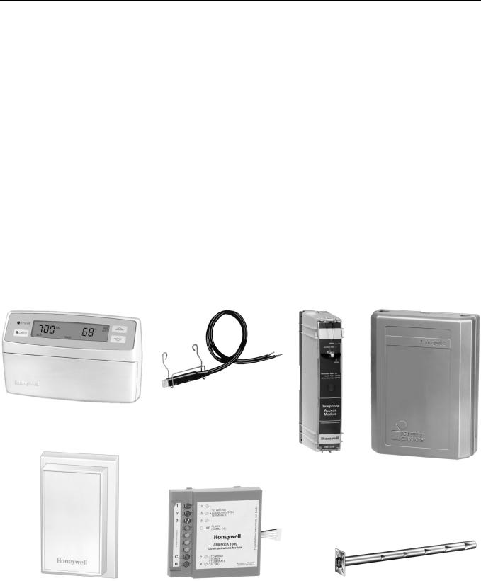
System Components and Accessories (See Fig. 1):
C7089A1002 Outdoor Sensor: Used to measure outdoor temperature.
C7100A1015 Discharge Air Sensor: Used to sense temperature in discharge or return air.
C7189A1001 Remote Indoor Sensor: Used for remote sensor applications.
CM8900A1009 Communication Module: Used for remote communication.
W8735B1003 Telephone Access Module: Used for remote communication.
202689A Mounting Plate Accessory: Used when C7189A Remote Indoor Sensor cannot cover wall marks from old thermostat.
205224A Wall Cover Plate: Used when PC8900A Control Panel cannot cover wall marks from old thermostat.
32007496-001 Replacement Door: Used for PC8900A Control Panel.
Dimensions:
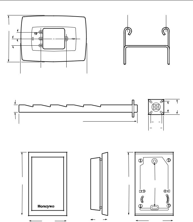
205224A: See Fig. 2.
C7089A: See Fig. 3.
C7100A: See Fig. 4.
C7189A: See Fig. 5.
PC8900A: See Fig. 6.
W8900A-C: See Fig. 7.
Operating Ambient Temperature Range:
NOTES: System is capable of turning on heat at 0°F (-18°C). C7089A: -40° to 128°F (-40° to 53°C).
C7100A: 40° to 150°F (4° to 66°C). C7189A: 40° to 95°F (4° to 35°C). PC8900A: 40° to 110°F (4° to 43°C). W8900A-C: -40° to 150°F (-40° to 66°C).
Shipping Temperature Range (All Components): -20° to 150°F (-29° to 66°C).
Operating Relative Humidity Range (All Components):
5 percent RH to 90 percent RH, noncondensing.
Mounting Means:
C7089A Outdoor Sensor: Mounts outside of living space using locally obtained mounting hardware.
C7100A Discharge Air Sensor: Mounts in discharge air duct, near air exchanger in a 2 x 4 in. outlet box or on a flat duct or plenum surface. The temperature sensor probe passes through a 7/8 in. knockout in the 2 x 4 in. outlet box.
C7189A Remote Indoor Sensor: Mounts directly on the wall using mounting screws and anchors provided.
PC8900A Control Panel:
Without Remote Sensor: Mounts directly on the wall in living space using mounting screws and anchors provided.
With Remote Sensor: Mounts directly on the wall in a closet or other convenient location using mounting screws and anchors provided.
W8900A-C Remote Module: Mounts directly on the wall, near HVAC equipment or cold air return, using mounting screws and anchors provided.
Table 1. W8900A-C Models.
Model |
Use with |
Heat |
Cool |
Vent |
Humidity |
Humidity |
Use with |
System Type |
Stages |
Stages |
Adjustment |
Adjustment Heat |
Adjustment Cool |
||
W8900A |
Conventional |
2 |
2a |
yes |
yes |
yes |
PC8900A |
W8900B |
Heat pump |
3 |
2 |
yes |
yes |
yes |
PC8900A |
|
|
|
|
|
|
|
|
W8900C |
Conventional |
2 |
2 |
yes |
yes |
yesb |
PC8900A |
a Models with O and B terminals have single stage cooling. b Uses reheat. See Operation section.
ORDERING INFORMATION
When purchasing replacement and modernization products from your TRADELINE® wholesaler or distributor, refer to the TRADELINE® Catalog or price sheets for complete ordering number.
If you have additional questions, need further information, or would like to comment on our products or services, please write or phone:
1.Your local Home and Building Control Sales Office (check white pages of your phone directory).
2.Home and Building Control Customer Relations Honeywell, 1885 Douglas Drive North
Minneapolis, Minnesota 55422-4386 (800) 328-5111
In Canada—Honeywell Limited/Honeywell Limitée, 35 Dynamic Drive, Scarborough, Ontario M1V 4Z9.
International Sales and Service Offices in all principal cities of the world. Manufacturing in Australia, Canada, Finland, France, Germany, Japan, Mexico, Netherlands, Spain, Taiwan, United Kingdom, U.S.A.
68-0173—3 |
2 |
Finish:
C7189A Wall Mount Remote Indoor Sensor: Premier White® color.
PC8900A Control Panel: Premier White® color. W8900A-C Remote Module: Charcoal gray color.
Clock Accuracy: ± 1 minute per month.
Approvals:
FCC Class B: Pending.
NEMA DC-3: Not required.
Batteries: No batteries required. During power outages, time is retained for six hours. All programmed setpoints and times are retained indefinitely.
Resistance Characteristics of Sensors:
C7089A Outdoor Sensor: PTC Sensor. See Fig. 39 in the Operation section for sensor resistance characteristics.
C7100A Discharge Air Sensor: See Fig. 39 in the Operation section for sensor resistance characteristics.
C7189A Remote Indoor Sensor: NTC Sensor. See Fig. 40 in the Operation section for sensor resistance characteristics.
Auxiliary Heat and Emergency Heat Indication: PC8900A display indicates when auxiliary heat and emergency heat are activated.
Input Ratings:
20 to 30 Vac, 50/60 Hz.
Heat Pump Failure Input (L Terminal on W8900B Models): 24 Vac load, 50/60 Hz, 0.3 VA load.
CO2 Monitor Input (CO2 Terminal on all W8900A-C Models): 24 Vac load, 50/60 Hz, 0.3 VA load.
Output Ratings:
Humidity Control Output Relay: 50 VA at 24 Vac. Ventilation, W1, W2, Y1, Y2, E, G, O, B, AUX, Y1/W1:
a.1.5A running, 3.5A inrush at 200,000 cycles
(30 Vac).
b.1.5A running, 7.5A inrush at 100,000 cycles
(30 Vac).
Run: 40% power factor minimum.
Inrush: 50% power factor minimum.
Temperature Setting Range: PC8900A: 45° to 88°F (7° to 31°C).
Humidity Setting Range:
PC8900A: 10 to 80% RH.
Cooling: 40 to 80% RH.
Heating: 10 to 80% RH.
Calibration: C7089A, C7100A, C7189A, and PC8900A are factory calibrated and require no field calibration.
CO2 Monitors: The W8900A-C allows for connection of a CO2 Monitor with uncommitted contacts.
C7089A
PC8900A Outdoor Sensor
Comfort Center™
Control Panel
W8735B |
W8900A-C |
Telephone Access |
Remote Module |
Module |
|
C7189A |
CM8900A |
C7100A |
Remote Indoor Sensor |
Communication Module |
Discharge Air Sensor |
Fig. 1. System components and accessories.
3 |
68-0173—3 |
6
(152)
7/8 (22)
7/8
(22)
 3-1/4 (83)
 8-1/2 (216)
M7513
Fig. 2. Dimensions for 205224A Wall Cover Plate in in. (mm).
3/4  13-1/4 (336) (19)
 1-1/2 (38)
M4488
Fig. 3. Dimensions for C7089A Outdoor Sensor Mounting Clip in in. (mm).
1-3/16 1-13/16
(30) (46)
1-3/16  (30)
(30) 
M4461
 1-13/16
(46)
Fig. 4. Dimensions for C7100A Discharge Air Sensor in in. (mm).
4-5/8 |
4-5/8 |
|
(117) |
(117) |
3-1/4 |
|
|
|
|
|
(83) |
|
|
2-3/4 (70) |
|
|
|
1-1/8 |
|
|
|
2-3/4 (70) |
|
|
|
|
|
|
|
|
|
|
|||
|
|
|
|
|
|
|
|
|
|||
|
|
|
|
|
|
|
|
|
|||
|
|
|
|
|
|
|
|
|
|||
|
|
|
|
|
|
|
|
|
|||
|
|
|
|
|
(29) |
|
|
|
|
|
|
M4465 |
FRONT VIEW |
|
SIDE VIEW |
|
FRONT VIEW (COVER OFF) |
||||||
Fig. 5. Dimensions for C7189A Remote Indoor Sensor in in. (mm).
68-0173—3 |
4 |
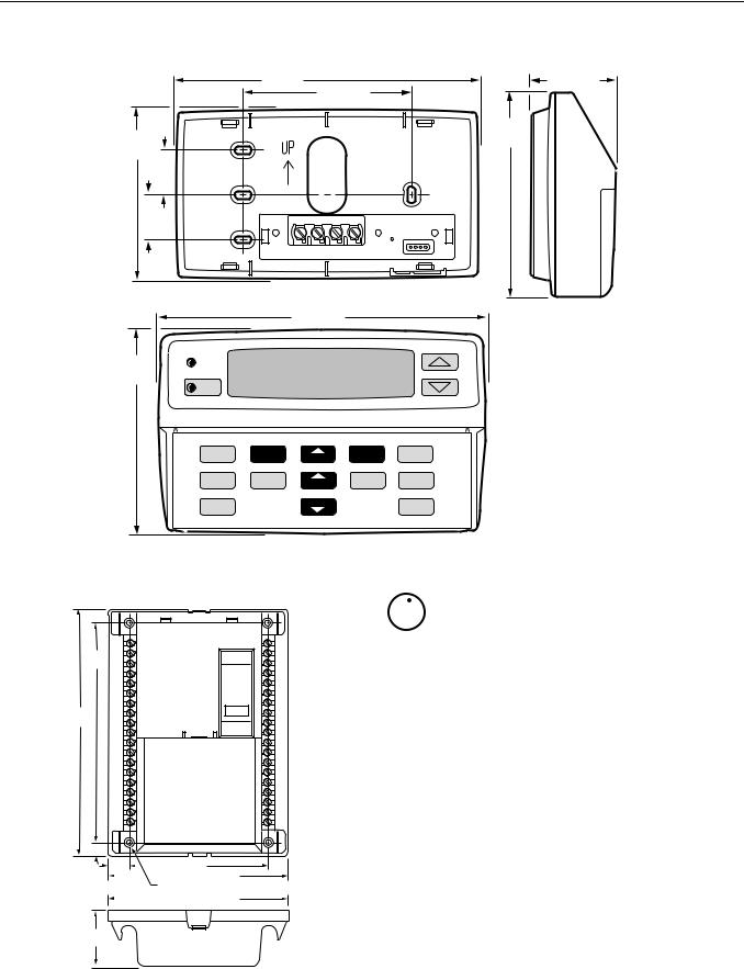
6 (152) |
1-5/8 (41) |
|
3-1/4 (83) |
|
4 |
3-3/8 |
(102) |
(86) |
|
7/8 |
|
(22) |
|
7/8 |
|
(22) |
|
6-3/8 (162)
4 |
SYSTEM |
|
|
(102) |
|
|
CHECK |
SET |
SYSTEM |
|
FAN |
HEAT/COOL |
|
|
CLOCK |
HEAT OFF COOL |
DAY |
AUTO ON CIRC |
SETPOINTS |
|
|
SELECT |
HUMIDITY |
|
VENTILATE |
HOLD |
NOTE: |
|
PERIOD |
TIME |
|||||
|
|
|
PC8900 SHOWN WITH |
|||
|
|
|
|
|
||
CANCEL |
|
TIME |
|
RUN |
COVER REMOVED. |
|
|
|
|
||||
|
|
|
|
M6356
Fig. 6. Dimensions for PC8900A Control Panel in in. (mm).
7-13/16
(197)
8-3/4
(222)
1/2 (12)
3/4 |
|
4-7/8 (124) |
|
(19) |
|
||
|
|
|
|
|
|
|
6-3/8 (163) |
|
(4) 3/8 (5) |
||
|
|
||
|
|
|
6-3/8 (163) |
|
|
|
|
2
(51)
NOTE: W8900 SHOWN WITH COVER REMOVED. |
M6355 |
Fig. 7. Dimensions for W8900A-C Remote Module in in. (mm).
 MERCURY NOTICE
If this control is replacing a control that contains mercury in a sealed tube, do not place your old control in the trash.
Contact your local waste management authority for instructions regarding recycling and the proper disposal of this control or of an old control containing mercury in a sealed tube.
If you have questions, call Honeywell Inc. at 1-800-468-1502, Monday through Friday, 7:00 a.m. to 5:30 p.m., Central time.
INSTALLATION
When Installing this Product…
1.Read these instructions carefully. Failure to follow instructions can damage the product or cause a hazardous condition.
2.Check the ratings on the product to make sure the product is suitable for your application.
3.Installer must be a trained, experienced service technician.
4.After completing installation, use these instructions to check out product operation.
5 |
68-0173—3 |
 CAUTION
Disconnect power supply before wiring to prevent electrical shock or equipment damage.
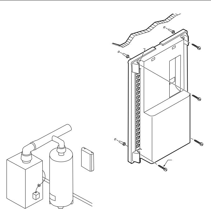
Mounting the W8900A-C Remote Module
Locate the W8900A-C in the equipment room near the HVAC equipment. See Fig. 8.
 CAUTION
Do not mount the W8900A-C inside any HVAC equipment. Mounting the W8900A-C inside HVAC equipment can cause damage to the W8900A-C.
1.Grasp the top edge of the W8900A-C cover, either at thecenterorbothcorners,andpullitofffromthebase.
2.Locate the four mounting holes. See Fig. 9.
3.Position the W8900A-C on wall or cold air return. Level the W8900A-C for appearance only; the device will function properly even when not level. Use a pencil to mark the mounting holes on the wall.
WALL |
W8900 |
|
MOUNTING
HOLES (4)
W8900
FURNACE OR BOILER |
WATER HEATER |
M4459
Fig. 8. W8900A-C location example.
4.Remove the W8900A-C from the wall, and drill 3/16 in. holes in the wall (if drywall) as marked. For firmer material such as plaster or wood, drill 7/32 in. holes. Gently tap anchors (provided) into drilled holes until flush with the wall.
5.Reposition the W8900A-C over the holes. Loosely insert the four mounting screws (included) into the holes.
MOUNTING
SCREWS (4)
M4463
Fig. 9. Mounting W8900A-C Remote Module.
Wiring the W8900A-C to the HVAC Equipment
 CAUTION
Disconnect power supply before connecting wiring to prevent electrical shock or equipment damage.
Wiring must comply with applicable codes, ordinances, and regulations.
IN REPLACEMENT INSTALLATION:
1.Locate the terminal wiring strip on the old thermostat.
2.Note the wire color for each wiring terminal used.
3.Remove the wires connected to the old thermostat and other controls. Tape off unused wires.
4.Use Table 2 or 3 to identify the W8900A-C terminal labels. Connect the same loads that were connected to the old thermostat to the W8900A-C Remote Module with a new bundle of 18-gauge color-coded thermostat wire; see Fig. 10. See Fig. 11 through 20 for wiring diagrams for specific equipment applications.
68-0173—3 |
6 |

IMPORTANT
Be sure to connect the C terminal to transformer common.
IN NEW INSTALLATION:
1.Locate the terminal strip(s) on the HVAC equipment.
2.Refer to Fig. 11 through 20 for wiring diagrams for specific equipment applications.
3.Connect all loads to the appropriate W8900A-C wiring terminal using 18-gauge, color-coded thermostat wire; see Fig. 10.
4.Use a small screwdriver to connect the loads. Do not overtighten; device can be damaged.
W8900
FOR STRAIGHT
CONNECTION—
STRIP 5/16 IN. (8 MM)
FOR WRAPAROUND
CONNECTION—
STRIP 7/16 IN. (11 MM)
M4464
|
Fig. 10. Proper wiring technique for |
||
|
W8900A-C and PC8900A. |
||
|
Table 2. Conventional Applications (W8900A or C). |
|
|
|
|
|
|
W8900A, C Terminal Designation |
Function |
|
Existing Thermostat Designation |
1 |
PC8900A Control Panel |
|
— |
2 |
PC8900A Control Panel |
|
— |
3 |
PC8900A Control Panel |
|
— |
4 |
PC8900A Control Panel |
|
— |
B |
Heating, changeover valve |
|
B |
C |
24 Vac Transformer Common |
|
C |
CO2 |
Carbon Dioxide Monitor |
|
— |
VNT |
VNT Relay |
|
— |
G |
Fan Relay |
|
G |
GND |
Ground |
|
— |
HUM |
Humidity Relay |
|
— |
OUT |
Outdoor Air Temperature Sensor |
|
— |
O |
Cooling, Changeover Valve |
|
O |
R |
24 Vac System Transformer |
|
R |
RC |
24 Vac Cooling Transformer |
|
RC |
RH |
24 Vac Heating Transformer |
|
RH |
S, S1 |
Remote Air Temperature Sensor |
|
— |
See note a |
Fan Control—Evaporative Cooling |
|
F |
See note b |
Heat Pump Contactor |
|
P |
T, T1 |
Discharge Air Temperature Sensor |
|
— |
W1 |
Heating Relay |
|
W |
W1 |
Stage 1 Heat Relay |
|
W1 |
W2 |
Stage 2 Heat Relay |
|
W2 |
Y1 |
Cooling Relay |
|
Y |
Y1 |
Stage 1 Cool Relay |
|
Y1 |
Y2 |
Stage 2 Cool Relay |
|
Y2 |
See note c |
Fan Control (Honeywell dual fuel thermostat [T834]) |
|
1 |
See note c |
Fan Control (Honeywell dual fuel thermostat [T834]) |
|
2 |
See note d |
Filter Light |
|
X |
none |
Remote Timer Contacts |
|
Z |
a PC8900A/W8900A,C are not compatible with evaporative cooling equipment.
b In single stage heat pump applications, jumper W1 and Y1 and connect to Y. Configure the system for Auto Fan in Heat. c Dual fuel fan feature configured in installer setup.
d Filter light feature available in PC8900A fan accumulation timer feature.
7 |
68-0173—3 |

Table 3. Heat Pump Applications (W8900B).
W8900B Terminal |
|
Existing Thermostat |
Existing Thermostat |
Function |
Designations |
Designations |
|
Designations |
(Standard) |
(Customer Specials) |
|
1 |
PC8900A Control Panel |
— |
— |
2 |
PC8900A Control Panel |
— |
— |
|
|
|
|
3 |
PC8900A Control Panel |
— |
— |
|
|
|
|
4 |
PC8900A Control Panel |
— |
— |
|
|
|
|
AUXa |
Stage-3 heat control (strip heat) |
W3 |
— |
B |
Heating, changeover valve |
B |
— |
|
|
|
|
C |
24 Vac transformer common |
C |
X,B |
|
|
|
|
CO2 |
Carbon dioxide monitor |
— |
— |
E |
Emergency heat relay |
E |
K |
VNT |
VNT relay |
— |
— |
|
|
|
|
G |
Fan relay |
G |
F |
|
|
|
|
GND |
Ground |
— |
— |
L |
System monitor |
L |
L |
|
|
|
|
O |
Cooling, changeover valve |
O |
R |
|
|
|
|
R |
24 Vac system transformer |
R |
V |
S, S1 |
Remote Air Temperature Sensor |
— |
— |
|
|
|
|
T, T1 |
Discharge Air Temperature Sensor |
— |
— |
|
|
|
|
W2b |
Stage-2 heat control (compressor) |
W2 |
H2,Y,R4 |
Y1/W1c |
Compressor contactor |
— |
RS |
Y1/W1c |
Compressor contactor |
Y |
M |
Y1/W1c |
Stage-1 cool control |
Y1 |
C1,M |
Y1/W1c |
Stage-1 heat control |
W1 |
H1,R3 |
Y2 |
Stage-2 cool control |
Y2 |
C2 |
None |
Clogged filter switch or common connection |
X |
X1,X2,C |
|
|
|
|
None |
Defrost |
— |
P |
|
|
|
|
None |
HSII Control Panel |
— |
L,C,H |
None |
LEDs |
— |
A,A1,A2,Z,C,L |
|
|
|
|
None |
LO and HI speed fan relays |
— |
R1,R2 |
|
|
|
|
None |
Momentary circuit, changeover |
— |
O |
None |
Outdoor thermistor |
T |
A |
|
|
|
|
Outd |
External temperature readout, T relay |
— |
— |
aAUX controls the auxiliary heat like W2, and allows additional stages of auxiliary heat with outdoor thermostats while maintaining the proper second stage anticipation.
b For systems without 2nd stage heat, configure W2 to No.
c For systems requiring separate W1 and Y1 terminals for proper heat pump operation, refer to Fig. 18 and 19. d Replace existing sensor with C7089A Outdoor Sensor.
68-0173—3 |
8 |
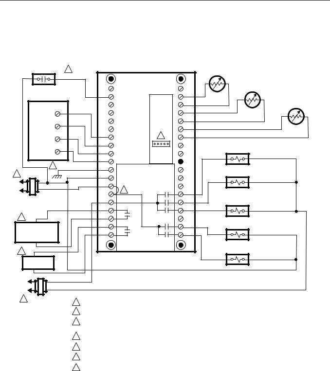
WIRING DIAGRAMS
W8900A,C Hookup Diagrams
CO2 MONITOR |
4 |
W8900A,C |
|
C7189A REMOTE AIR |
|
|
TEMPERATURE SENSOR |
||
|
|
|
|
C7100 DISCHARGE AIR |
|
|
|
|
TEMPERATURE SENSOR |
PC8900 |
CO2 |
|
S1 |
|
|
|
|
C7089A OUTDOOR AIR |
|
|
|
|
S |
|
|
|
|
TEMPERATURE SENSOR |
|
|
|
|
|
|
1 |
|
|
T1 |
|
|
|
|
|
|
|
|
|
T |
|
2 |
|
|
OUT |
|
|
|
|
|
|
3 |
1 |
7 |
OUT |
|
2 |
|
|
|
|
|
|
|
|
|
4 |
3 |
|
|
FAN RELAY |
|
|
|
|
|
|
4 |
|
LED |
|
6 |
GND |
|
|
STAGE 2 |
|
|
|
||
|
|
|
|
|
1 |
C |
|
|
COOL RELAY |
|
|
|
|
|
L2 |
R |
|
|
|
L1 |
RH |
2 |
G |
|
|
|
|||
(HOT) |
RC |
|
Y2 |
STAGE 1 |
HEATING |
|
COOL RELAY |
||
|
|
|
||
TRANSFORMER |
HUM |
|
Y1 |
|
3 |
HUM |
|
|
|
|
|
|
|
|
|
VNT |
|
W1 |
STAGE 1 |
HUMIDIFIER |
|
HEAT RELAY |
||
|
|
|
||
OR DEHUMIDIFIER |
VNT |
|
W2 |
|
EQUIPMENT |
|
|
|
|
|
|
|
|
STAGE 2 |
5 |
|
|
|
HEAT RELAY |
|
|
|
|
VENTILATION |
EQUIPMENT |
L1
(HOT)
L2
1 COOLING |
1 POWER SUPPLY. PROVIDE DISCONNECT MEANS AND OVERLOAD PROTECTION AS REQUIRED. |
|
TRANSFORMER |
||
|
2JUMPER R TO RH FOR SINGLE HEAT TRANSFORMER APPLICATIONS.
3CONFIGURE PC8900 FOR HUMIDITY CONTROL IN HEATING MODE (HUMIDIFIER) OR COOLING MODE (DEHUMIDIFIER) DURING INSTALLER SETUP .
4W8900 ALLOWS CONNECTION OF A CO2 MONITOR WITH UNCOMMITTED CONTACTS.
5SEE VENTILATION INSTRUCTIONS FOR WIRING.
6GROUNDING THE GND TERMINAL IS NOT RECOMMENDED.
7 CONNECTION FOR CM8900A REMOTE COMMUNICATIONS MODULE. |
M4479D |
|
Fig. 11. Hookup diagram for heating/cooling system in conventional system with multiple transformers.
9 |
68-0173—3 |
CO2 MONITOR
4
PC8900
1
2
3
4
6
1
L2
L1
(HOT)
SYSTEM TRANSFORMER
3HUMIDIFIER
OR DEHUMIDIFIER EQUIPMENT
5VENTILATION EQUIPMENT
|
W8900A,C |
|
CO2 |
|
S1 |
|
|
S |
|
|
T1 |
|
|
T |
|
|
OUT |
1 |
7 |
OUT |
|
|
|
2 |
|
|
3 |
|
|
4 |
|
LED |
GND |
|
|
C |
|
|
R |
2 |
|
|
|
|
RH |
|
G |
RC |
|
Y2 |
HUM |
|
Y1 |
HUM |
|
|
VNT |
|
W1 |
VNT |
|
W2 |
C7189A REMOTE AIR
TEMPERATURE SENSOR
C7100 DISCHARGE AIR
TEMPERATURE SENSOR
C7089A OUTDOOR AIR
TEMPERATURE SENSOR
FAN RELAY
STAGE 2
COOL RELAY
STAGE 1
COOL RELAY
STAGE 1
HEAT RELAY
STAGE 2
HEAT RELAY
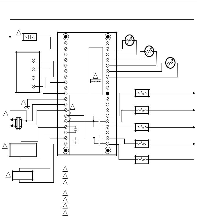
1POWER SUPPLY. PROVIDE DISCONNECT MEANS AND OVERLOAD PROTECTION AS REQUIRED.
2JUMPER R TO RH TO RC FOR SINGLE TRANSFORMER APPLICATIONS.
3DURING INSTALLER SETUP, CONFIGURE PC8900 FOR HUMIDITY CONTROL IN HEATING MODE (HUMIDIFIER) OR COOLING MODE (DEHUMIDIFIER).
4W8900 ALLOWS CONNECTION OF A CO2 MONITOR WITH UNCOMMITTED CONTACTS.
5SEE VENTILATION INSTRUCTIONS FOR WIRING.
6GROUNDING THE GND TERMINAL IS NOT RECOMMENDED.
7 |
CONNECTION FOR CM8900A REMOTE COMMUNICATIONS MODULE. |
M4478D |
|
Fig. 12. Hookup diagram for 1-stage or 2-stage heating and cooling in conventional system with single transformer.
68-0173—3 |
10 |
|
4 |
CO2 MONITOR |
|
W8900A,C |
|
C7189A REMOTE AIR |
|
|
|
||||
|
|
|
|
|
TEMPERATURE SENSOR |
|
|
|
|||||
|
|
|
|
|
|
|
|
|
|
|
|||
|
|
|
|
|
|
|
|
|
|
C7100 DISCHARGE AIR |
|
||
|
|
|
|
|
|
|
|
|
|
TEMPERATURE SENSOR |
|
||
|
PC8900 |
|
CO2 |
|
|
S1 |
|
|
|
|
|
|
|
|
|
|
|
|
|
|
|
|
|
C7089A OUTDOOR AIR |
|||
|
|
|
|
|
|
|
S |
|
|
|
|
||
|
|
|
|
|
|
|
|
|
|
|
TEMPERATURE SENSOR |
||
|
|
|
|
|
|
|
|
|
|
|
|
||
|
|
1 |
|
|
|
|
T1 |
|
|
|
|
|
|
|
|
|
|
|
|
|
|
|
|
|
|
|
|
|
|
|
|
|
|
|
T |
|
|
|
|
|
|
|
|
2 |
|
|
|
|
OUT |
|
|
|
|
|
|
|
|
3 |
|
1 |
|
7 |
OUT |
|
|
|
|
|
|
|
|
|
|
|
|
|
|
|
|
|
|
||
|
|
|
|
|
|
|
|
|
|
|
|
|
|
|
|
|
|
2 |
|
|
|
|
|
|
|
|
|
|
|
4 |
|
3 |
|
|
|
|
|
|
|
|
|
|
|
|
|
4 |
|
|
LED |
|
|
|
|
|
|
|
|
|
|
GND |
|
|
|
|
|
|
|
|
|
|
|
6 |
|
C |
|
|
|
|
|
FAN RELAY |
|
|
|
|
|
|
|
|
|
|
|
|
|
|
|||
|
|
|
|
|
|
|
|
|
|
|
|
||
|
|
|
|
R |
2 |
|
|
|
|
|
|
|
|
|
1 |
|
|
|
|
|
|
|
|
|
|
|
|
|
|
|
RH |
|
|
G |
|
|
|
|
|
|
|
|
|
|
|
|
|
|
|
|
|
|
|
||
L2 |
|
|
|
RC |
|
|
Y2 |
|
|
|
|
|
|
|
|
|
|
|
|
|
|
STAGE 1 |
|
|
|
||
|
|
|
|
|
|
|
|
|
|
|
|
|
|
L1 |
|
|
|
HUM |
|
|
Y1 |
|
|
COOL RELAY |
|
|
|
(HOT) SYSTEM |
|
HUM |
|
|
|
|
|
|
|
|
|
||
|
TRANSFORMER |
|
VNT |
|
|
W1 |
|
|
|
|
|
|
|
|
|
|
|
|
|
|
|
|
|
|
|
||
3 |
|
|
|
VNT |
|
|
W2 |
|
|
|
|
|
|
HUMIDIFIER OR |
|
|
|
|
|
|
|
|
|
|
|
||
|
|
|
|
|
|
|
|
|
|
|
|
||
|
DEHUMIDIFIER |
|
|
|
|
|
|
|
|
|
|
|
|
|
EQUIPMENT |
|
|
|
|
|
|
|
|
|
|
|
|
|
|
|
|
|
|
|
|
|
S8610U |
|
|
|
|
5 |
VENTILATION |
|
|
|
|
|
|
|
|
VENT |
|
|
|
EQUIPMENT |
|
|
|
|
|
|
|
|
|
|
|||
|
|
|
|
GND |
24V |
|
|
DAMPER |
|
||||
|
|
|
|
|
|
|
|
||||||
|
|
|
|
|
MV |
MV/PV PV |
(BURNER) |
GND |
24V |
TH-W |
PLUG |
SENSE |
SPARK |
|
|
PILOT |
COM |
MAIN |
|
|
|
|
|
|
|
|
|
|
|
|
|
VALVE |
|
SENSOR |
|
|
|
|
|
|
|
|
|
1ST |
2ND |
|
|
|
|
|
|
|
|
|
|
|
|
OPERATOR |
OPERATOR |
|
|
|
|
|
|
|
|
D892 VENT |
|
|
|
|
|
|
|
|
|
|
|
|
|
|
|
|
|
DUAL VALVE COMBINATION |
|
|
|
|
|
|
LIMIT |
|
DAMPER |
|
|
|
|
|
|
|
|
|
|
|
|
|
|||
|
|
GAS CONTROL |
|
|
|
|
|
|
|
|
|
|
|
|
|
|
IGNITER |
|
|
|
|
CONTROLLER |
|
||||
|
|
|
|
|
|
|
|
|
|||||
1POWER SUPPLY. PROVIDE DISCONNECT MEANS AND OVERLOAD PROTECTION AS REQUIRED.
2JUMPER R TO RH TO RC FOR SINGLE TRANSFORMER APPLICATIONS.
PILOT GAS SUPPLY
PILOT BURNER GROUND
3DURING INSTALLER SETUP, CONFIGURE PC8900 FOR HUMIDITY CONTROL IN HEATING MODE (HUMIDIFIER) OR COOLING MODE (DEHUMIDIFIER).
4W8900 ALLOWS CONNECTION OF A CO2 MONITOR WITH UNCOMMITTED CONTACTS.
5SEE VENTILATION INSTRUCTIONS FOR WIRING.
6GROUNDING THE GND TERMINAL IS NOT RECOMMENDED.
7 CONNECTION FOR CM8900A REMOTE COMMUNICATIONS MODULE. |
M4489D |
Fig. 13. Hookup diagram for heating/cooling intermittent pilot gas burning ignition system.
11 |
68-0173—3 |

|
4 CO2 MONITOR |
|
W8900A,C |
|
C7189A REMOTE AIR |
|
|
|
|
TEMPERATURE SENSOR |
|
|
|
|
|
|
C7100 DISCHARGE AIR |
|
|
|
|
|
TEMPERATURE SENSOR |
|
PC8900 |
CO2 |
|
S1 |
|
|
|
|
|
C7089A OUTDOOR AIR |
|
|
|
|
|
S |
|
|
|
|
|
TEMPERATURE SENSOR |
|
|
|
|
|
|
|
|
1 |
|
|
T1 |
|
|
|
|
|
|
|
|
|
|
|
T |
|
|
2 |
|
|
OUT |
|
|
|
|
|
|
|
|
3 |
1 |
10 |
OUT |
|
|
|
|
|
||
|
|
|
|
|
|
|
|
2 |
|
|
|
|
4 |
3 |
|
|
|
|
|
4 |
|
LED |
|
|
|
GND |
|
|
|
|
9 |
C |
|
|
|
|
|
R |
2 |
|
|
|
|
|
|
|
|
|
|
RH |
|
G |
|
|
|
RC |
|
Y2 |
|
|
|
HUM |
|
Y1 |
|
|
HUMIDIFIER OR |
HUM |
|
|
|
3 |
|
|
|
|
|
DEHUMIDIFIER |
|
|
|
|
|
|
VNT |
|
W1 |
|
|
|
EQUIPMENT |
|
|
||
|
|
|
|
|
|
|
|
VNT |
|
W2 |
|
8 |
VENTILATION |
|
EQUIPMENT |
||
|
|
7 |
7 |
7 |
ZONE |
2 THERMOSTAT |
ZONE 3 THERMOSTAT |
ZONE 4 THERMOSTAT |
W |
G C R |
W G C R |
W G C R |
|
5 |
|
|
|
|
|
R8239A1052 |
|
R8222B1067 |
R8222B1067 |
|
|
|
|
|
||
C |
W |
Y |
R |
G |
|
1 |
|
|
|
|
|
L2 |
|
|
|
|
|
|
24V |
|
|
|
|
L1 |
|
|
|
|
|
(HOT) |
|
|
|
6 |
6 |
|
|
|
|
ZONE 1 |
ZONE 2 |
|
|
|
|
VALVE |
VALVE |
1POWER SUPPLY. PROVIDE DISCONNECT MEANS AND OVERLOAD PROTECTION AS REQUIRED.
2JUMPER R TO RH TO RC FOR SINGLE TRANSFORMER APPLICATIONS.
3DURING INSTALLER SETUP, CONFIGURE PC8900 FOR HUMIDITY CONTROL IN HEATING MODE (HUMIDIFIER) OR COOLING MODE (DEHUMIDIFIER).
4W8900 ALLOWS CONNECTION OF A CO2 MONITOR WITH UNCOMMITTED CONTACTS.
R8222B1067
|
6 |
ZONE 3 |
ZONE 4 |
VALVE |
VALVE |
5USE ONE R8239 FOR EVERY FOUR ZONES.
6USE FOR 3-WIRE ZONE VALVE OR DAMPERS.
7ZONES 2, 3, 4 CAN BE CONTROLLED BY ADDITIONAL PC8900/W8900 OR OTHER THERMOSTATS.
8SEE VENTILATION INSTRUCTIONS FOR WIRING.
9GROUNDING THE GND TERMINAL IS NOT RECOMMENDED.
10 CONNECTION FOR CM8900A REMOTE COMMUNICATIONS MODULE. |
M4491D |
Fig. 14. Hookup diagram for 3-wire zone valves in Series 20 heating system with zone controls.
68-0173—3 |
12 |
CO2 MONITOR 3
PC8900 |
CO2 |
|
1
2
1
3
2
4 |
3 |
4
|
5 |
GND |
|
|
|
|
|
C |
|
|
R |
1 |
L2 |
RH |
|
||
|
|
|
|
L1 |
RC |
|
(HOT) |
HUM |
|
SYSTEM |
|
|
|
|
|
TRANSFORMER |
HUM |
|
|
VNT |
|
|
VNT |
2 |
HUMIDIFIER OR |
|
DEHUMIDIFIER |
|
|
|
|
|
|
EQUIPMENT |
|
4VENTILATION EQUIPMENT
W8900A,C |
|
C7189A REMOTE AIR |
|
|
TEMPERATURE SENSOR |
|
|
C7100 DISCHARGE AIR |
|
|
TEMPERATURE SENSOR |
|
S1 |
|
|
S |
C7089A OUTDOOR AIR |
|
TEMPERATURE SENSOR |
|
|
|
|
|
T1 |
|
T
OUT
6 OUT
 LED
LED
|
FAN RELAY |
G |
|
Y2 |
STAGE 1 |
|
|
Y1 |
COOL RELAY |
W1 |
|
W2 |
|
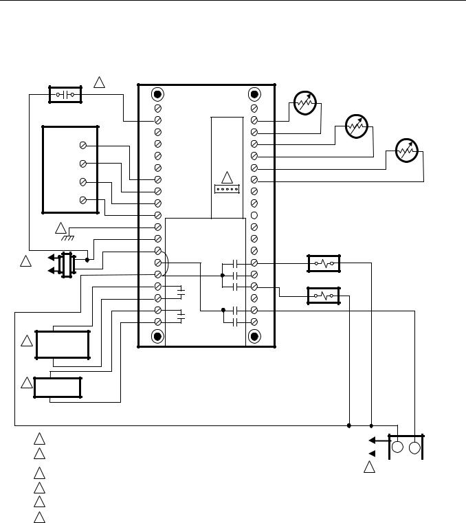
1POWER SUPPLY. PROVIDE DISCONNECT MEANS AND OVERLOAD PROTECTION AS REQUIRED.
2DURING INSTALLER SETUP, CONFIGURE PC8900 FOR HUMIDITY CONTROL IN HEATING MODE (HUMIDIFIER) OR COOLING MODE (DEHUMIDIFIER).
3W8900 ALLOWS CONNECTION OF A CO2 MONITOR WITH UNCOMMITTED CONTACTS.
4SEE VENTILATION INSTRUCTIONS FOR WIRING.
5GROUNDING THE GND TERMINAL IS NOT RECOMMENDED.
6CONNECTION FOR CM8900A REMOTE COMMUNICATIONS MODULE.
L1 |
|
|
(HOT) |
T |
T |
L2 |
|
|
|
|
OIL PRIMARY |
||||
1 |
||||
|
|
|
||
M4490D
Fig. 15. Hookup diagram in oil heating/electric cooling system (oil primary has its own transformer).
13 |
68-0173—3 |
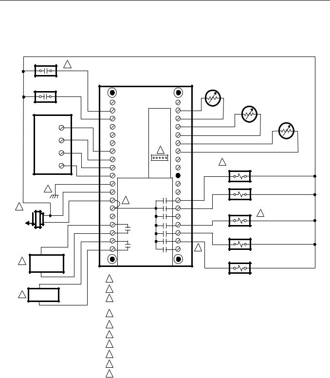
W8900B Hookup Diagrams
CO2 MONITOR 4
COMPRESSOR
MONITOR
PC8900
1
2
3
4
8
1
L2 

L1 |
(HOT) |
SYSTEM
TRANSFORMER
HUMIDIFIER OR 3 DEHUMIDIFIER
EQUIPMENT
7 |
VENTILATION |
|
EQUIPMENT |
||
|
W8900B |
|
|
C7189A REMOTE AIR |
|
|
|
|
|
TEMPERATURE SENSOR |
|
|
|
|
|
|
C7100 DISCHARGE AIR |
|
|
|
|
|
TEMPERATURE SENSOR |
|
CO2 |
|
S1 |
|
|
|
L |
|
S |
|
|
C7089A OUTDOOR AIR |
|
|
|
TEMPERATURE SENSOR |
||
|
|
|
|
|
|
|
|
T1 |
|
|
|
|
|
T |
|
|
|
|
|
OUT |
|
|
|
1 |
9 |
OUT |
|
|
|
|
|
|
|
|
|
2 |
|
|
|
|
|
3 |
|
|
5 |
CHANGEOVER |
|
|
|
|
RELAY |
|
|
|
|
|
|
|
|
4 |
|
LED |
|
|
|
GND |
|
|
|
|
|
C |
|
|
|
FAN RELAY |
|
|
|
|
|
|
|
R |
|
O/B |
|
|
|
2 |
|
|
|
|
|
RH |
|
G |
|
COMPRESSOR |
|
|
|
Y2 |
|
CONTACTOR |
6 |
|
|
|
|
|
|
HUM |
|
Y1/W1 |
|
|
|
HUM |
|
E |
|
EMERGENCY |
|
VNT |
|
|
|
HEAT RELAY |
|
|
AUX |
|
|
|
|
VNT |
|
W2 |
10 |
|
|
|
|
|
|
|
|
|
|
|
|
AUXILIARY |
|
|
|
|
|
HEAT RELAY |
|
1POWER SUPPLY. PROVIDE DISCONNECT MEANS AND OVERLOAD PROTECTION AS REQUIRED.
2JUMPER R TO RH.
3DURING INSTALLER SETUP, CONFIGURE PC8900 FOR HUMIDITY CONTROL IN HEATING MODE (HUMIDIFIER) OR COOLING MODE (DEHUMIDIFIER).
4W8900 ALLOWS CONNECTION OF A CO2 MONITOR WITH UNCOMMITTED CONTACTS.
5CONFIGURE PC8900 FOR CHANGEOVER IN HEATING MODE OR COOLING MODE.
6IF SEPARATE Y1 AND W1 TERMINALS ARE REQUIRED, REFER TO FIGURES 18 AND 19.
7SEE VENTILATION INSTRUCTIONS FOR WIRING.
8GROUNDING THE GND TERMINAL IS NOT RECOMMENDED.
9CONNECTION FOR CM8900A REMOTE COMMUNICATIONS MODULE.
10 CONFIGURE PC8900 FOR NO CONNECTION TO TERMINALS Y2, E, AUX AND W2 FOR |
|
SINGLE-STAGE HEAT PUMP SYSTEM. |
M4483D |
Fig. 16. Hookup diagram for 2-stage heat/1-stage cool in heat pump system.
68-0173—3 |
14 |
Loading...