


R4795A
Flame Safeguard
Primary Controls
The R4795A Protectorelay™ Primary Control provides solid state electronic flame safeguard protection for commercial and industrial gas or oil burners. It provides a prepurge period before each start, and intermittent pilot.
■120V models meet the requirements of Underwriters Laboratories Inc. Standard 795 for mechanical draft and atmospheric burner inputs from 400,000 to 2,500,000 Btu.
■Meets Underwriters Laboratories Inc. requirements for oil burner group 8 when 30, 60, or 90 second prepurge timer is used.
■Selection of solid state, plug-in prepurge timers provides 7, 10, 30, 60, or 90 second prepurge time.
■Includes terminals for connection of air flow switch to prove airflow before prepurge period starts, during purge, and during the entire Run period.
■Choice of interchangeable, color-coded, solid state, plug-in flame signal amplifiers allows use with rectification or ultraviolet type flame detectors.
■Safe-start feature prevents start when flame or flame simulating condition is present.
■Recycles through prepurge if the flame goes out while burner is running. If pilot flame is not reestablished, safety switch trips and locks out system.
■A tripped safety switch must be manually reset to restore operation.
■Push-to-reset safety switch is dust-resistant enclosed.
■Optional spdt alarm contacts operate external alarm on safety switch lockout.
■Ignition interference circuit (rectification amplifier only) protects electronic network from high voltage ignition crossover and provides visual indication when interference occurs.
■Solid state circuitry eliminates vacuum tube replacement and increases resistance to vibration. Application of power not required during Off cycle; no tube warmup before starting.
■Easy-to-replace plug-in components result in faster service and reduced inventory.
■Flame current jack, located on the amplifier, provides means of plugging in a microammeter to measure the flame signal with system operating.
■Easy mounting and removal through use of captive mounting screws, which also serve as electrical connections.
■Durable thermoplastic mounting base.
■Models available with -40°F (-40°C) temperature rating.
CONTENTS |
|
Specifications ................................................. |
2 |
Ordering Information ..................................... |
2 |
Installation ..................................................... |
4 |
Checkout ......................................................... |
8 |
Operation ..................................................... |
11 |
Troubleshooting ........................................... |
11 |
Service .......................................................... |
13 |
S.Y. • Rev. 12-94 • ©Honeywell Inc. 1994 |
1 |
6060-2285- —-77 |

R4795A
SPECIFICATIONS • ORDERING INFORMATION
Specifications
R4795A Flame Safeguard Primary Control recycles once after flame failure to try to re-establish pilot before lockout. Use with R7289A Amplifier and rectifying flame rod, rectifying photocell, or C7012A,C Purple Peeper Ultraviolet Flame Detector; or with R7290A Amplifier and C7027A, C7035A, or C7044A Minipeeper Ultraviolet Flame Detector.
AMBIENT TEMPERATURE RATINGS:
Minimum: -20°F (-29°C). Special models to -40°F (-40°C). Maximum: +125°F (52°C) at 60 Hz; +115°F (46°C) at 50 Hz. -40°F (-40°C) models have maximum ambient of +115°F (46°C) at 60 Hz, +105°F (40°C) at 50 Hz. Subtract 10°F (6°C) when optional alarm contacts are
included. ELECTRICAL RATINGS:
Voltage and Frequency: Single voltage models only: 100V, 120V, 200V, 220V, 50/60 Hz. As ordered.
Power Consumption (at 60 Hz):
6.0W max using rectifying flame rod or photocell.
8.0W max using ultraviolet flame detector.
FLAME FAILURE RESPONSE TIME: 0.8 or 3 seconds nominal, as ordered.
SAFETY SWITCH TIMING (LOCKOUT TIMING): 15 seconds nominal.
RECYCLE TIME: Almost immediate after Flame Failure Response Time.
FLAME ESTABLISHING PERIOD: May last up to safety switch lockout time or until flame is recognized by device.
ALARM CONTACTS (Optional): Isolated spdt contacts. Male quick-connect terminals (female quick-connects included). See Terminal Ratings. –40°F (–40°C) models have isolated spdt alarm contacts.
Ordering Information
When purchasing replacement and modernization products from your TRADELINE® wholesaler or your distributor, refer to the TRADELINE® catalog or price sheets for complete ordering number, or specify:
1. |
Order number. |
3. |
Flame failure response time. |
2. |
Voltage and frequency. |
4. |
Alarm contacts, if desired (included with -40°F [-40°C] models.) |
Order separately: |
|
|
|
1. |
R7289A Rectification Amplifier, |
3. |
Plug-in prepurge timer model number |
|
or R7290A Ultraviolet Amplifier. |
|
and timing (7, 10, 30, 60, or 90 seconds). |
|
Specify flame failure response time. |
4. |
Q270A1024 Mounting Subbase. |
2. |
Flame detector to match amplifier. |
5. |
Accessories, if desired. |
If you have additional questions, need further information, or would like to comment on our products or services, please write or phone:
1.Your local Honeywell Home and Building Control sales office (check white pages of phone directory).
2.Home and Building Control Customer Logistics Honeywell Inc., 1985 Douglas Drive North Minneapolis, Minnesota 55422-4386
In Canada—Honeywell Controls Limited/Honeywell Limitée, 35 Dynamic Drive, Scarborough, Ontario M1V 4Z9. International sales and service offices in all principal cities of the world. Manufacturing in Australia, Canada, Finland, France, Germany, Japan, Mexico, Netherlands, Taiwan, United Kingdom, U.S.A.
60-2285—7 |
2 |

R4795A
SPECIFICATIONS
TERMINAL RATINGS:
|
|
|
|
Terminal |
Load |
|
Rating |
|
|
|
|
3 |
Pilot Valve |
125 |
VA pilot duty. |
|
|
|
|
|
Intermittent Ignitiona |
360 |
VA. |
4 |
Interrupted Ignition |
360 |
VA. |
|
|
|
|
5 |
Main Fuel Valve(s) |
125 |
VA pilot duty, or 25 VA pilot duty plus one or more motorized |
|
|
valves with total rating up to 400 VA opening, 200 VA holding. |
|
|
|
|
|
6-7 |
Airflow Switch |
0.6A at 30 Vdc. |
|
|
|
|
|
8 |
Fan or Burner Motor |
9.8A full load, 58.8A locked rotor (inrush) at 120 Vac. 4.9A full |
|
|
|
load, 29.4A locked rotor (inrush at 220 and 240 Vac. |
|
|
|
|
|
Isolated Spdt Alarm |
Alarm |
3A at 24 volts, or 1A at 120 volts, in a suitable wiring enclosure. |
|
Terminals (Optional) |
|
|
|
|
|
|
|
a When ignition is connected to terminal 3, terminal 4 cannot be used.
NOTE: Allowable inrush can be up to ten times the pilot duty rating.
Example:
Pilot duty rating = 125 VA.
At 120V, running current is 125/120 = 1.05A. Maximum allowable inrush is 10 times 1.05 = 10.5A.
DIMENSIONS (Includes Cover and Subbase): Approximately 5 x 5 x 5 in. (127 x 127 x 127 mm).
MOUNTING: Q270A1024 Subbase. Ordered separately. APPROVALS:
Underwriters Laboratories Inc Listed: 120V models using 30, 60, or 90 second prepurge timers including – 40°F (–40°C) rated models; file no. MP268, guide no. MCCZ.
Underwriters Laboratories Inc. Component Recognized: 120 volt models using 7 or 10 second prepurge timers including -40°F (-40°C) rated models; file no. MP268, guide no. MCCZ2.
Canadian Standards Association Certified: 120V models only, including -40°F (-40°C) rated models; file no. LR95329.
Factory Mutual Approved: R4795A 120V models; report no. 18774. -40°F (-40°C) rated models; report no. 19608.1.
American Gas Association Design Certified: File no. 21-6 (F and F1).
ACCESSORIES:
W136A Test Meter (includes 117053 Meter Connector Plug).
Flame Simulator: 203659 Ultraviolet 121708 Rectification 123514B Ultraviolet
117053 Meter Connector Plug FSP1535 Tester for operational check Q624 Solid State Spark Generator
118702E Remote Reset Cover, 120 Vac, 60 Hz
202471C Reset Cover for R4795A ADDITIONAL CONTROLS:
Order all additional controls separately:
Q270A1024 Mounting Subbase.
Plug-In Flame Signal Amplifiers, Rectification Type (Green Backplate): For use with C7004B C7005A, and B, C7008A, or Q179A,C Rectifying Flame Rods (for gas); C7003A, C7010A, C7013A or C7014A Photocells (for oil); or C7012A,C Purple Peeper Ultraviolet Flame Detectors (for gas or oil).
R7289A1004 Amplifier: 3 sec nominal flame failure response.
R7289A1012 Amplifier: 0.8 sec nominal flame failure response.
R7289A1020 Amplifier: 3 sec nominal flame failure response, -40°F (-40°C) ambient temperature.
UltravioletType(PurpleBackplate):ForusewithC7027A, C7035A or C7044A Minipeeper Ultraviolet Flame Detectors (for gas or oil).
R7290A1001 Amplifier: 3 sec nominal flame failure response.
R7290A1019 Amplifier: 0.8 sec nominal flame failure response.
R7290A1027 Amplifier: 3 sec nominal flame failure response, -40°F (-40°C) ambient temperature.
ST71A Plug-In Prepurge Timer (ordered separately): Minimum Timings: 7, 10, 30, 60, and 90 seconds (as
ordered).
Maximum Timings: 8.4, 12, 36, 72, and 108 seconds at room ambient temperature.
RecommendedLimits:L404A;L604A,L;L4006A,C,E; L4008A,E,F; L6006A,B: These controllers were Underwriters Laboratories Inc. tested for breaking loads only, at 120 Vac, for the total rating of 9.8A full load, plus 360VA ignition, plus 250 VA pilot duty.
Flame Detector: As specified in Plug-In Flame Signal Amplifiers listed above.
3 |
60-2285—7 |
R4795A
INSTALLATION
Installation
 CAUTION
1.Installer must be a trained, experienced, flame safeguard control service technician.
2.Disconnect power supply before beginning installation to prevent electrical shock and equipment damage.
3.All wiring must comply with applicable local electrical codes, ordinances, and regulations.
4.Voltage and frequency of the power supply connected to this control must agree with those marked on the device.
5.Loads connected to the control terminals must not exceed those listed in the Specifications section.
6.All external timers must be Listed or Component Recognized by authorities having jurisdiction for the specific purpose for which they are used.
7.Some authorities having jurisdiction prohibit the wiring of any limit or operating contacts in series with the main fuel valve(s).
8.Perform all required checkout tests after installation is complete.
Follow the burner manufacturer’s instructions, if supplied. Otherwise proceed as follows.
 CAUTION
Ultraviolet sensing tubes have a life expectancy of 40,000 hours of continuous use within the ambient temperature and voltage ratings. Worn out ultraviolet sensing tubes can result in failure of the sensing tube to properly discriminate between flame conditions.
For systems using R4795A with R7290 Amplifiers, use C7027, C7035 and C7044 Flame Detectors only on burners that cycle On and Off at least once every 24 hours. Appliances with burners that remain on for 24 hours continuously or longer should use the C7012E Flame Detector with the R7247C Amplifier or the C7076A Flame Detector with the R7476A Amplifier as the ultraviolet flame detection system.
LOCATION
Temperature
Install the R4795A where the surrounding temperatures remain within the Ambient Operating Temperature Ratings listed in the Specifications section.
Humidity
Install the R4795A where the relative humidity never reaches the saturation point. Condensation of moisture on the R4795A may cause enough leakage to short the flame signal to ground and prevent the burner from starting.
Vibration
Do not install the R4795A where it could be subject to excessive vibration. Vibration shortens the life of the electronic and mechanical components.
Weather
The R4795A is not designed to be weathertight. If it is installed outdoors, use a suitable weathertight enclosure.
Mounting The Subbase
Locate the subbase where ambient temperature is within the specified rating.
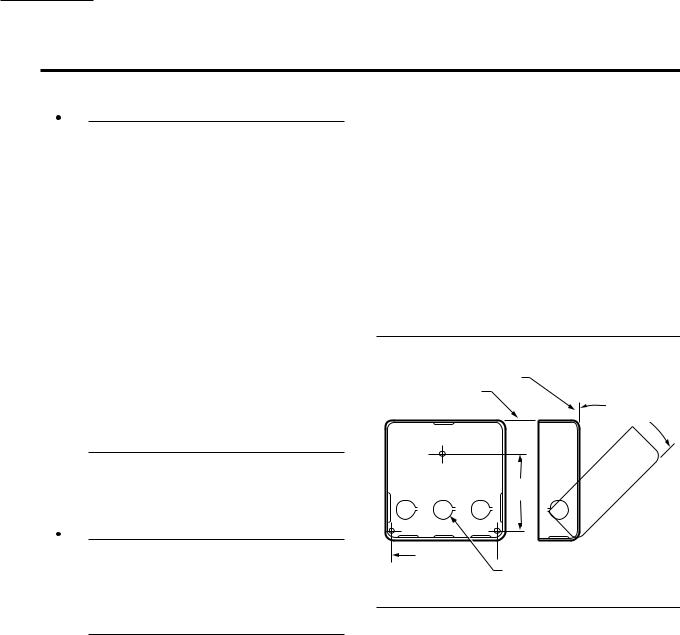
Mount the subbase so the top and bottom are horizontal and the back is vertical. The subbase can lean backward as much as 45 degrees when necessary. See Fig. 1.
Fig. 1—Subbase mounting dimensions in in.
(mm).
VERTICAL
HORIZONTAL
45 DEGREES MAXIMUM LEAN
2-7/8
(73.0)
4-1/8 (104.8) 
KNOCKOUTS (9) FOR |
|
1/2 IN. (13) CONDUIT |
M8681 |
WIRING TO SUBBASE
1.All wiring must comply with applicable codes, ordinances, and regulations. All wiring to the Q270A Universal Mounting subbase must be NEC Class 1.
2.When wiring the Q270A for use with the R4795A, use the terminal designations 8, 7, and 6 (printed in yellow).
3.For normal installations, use moisture-resistant No. 14 wire suitable for at least 167°F (75°C).
4.For high temperature installations, use moisture-re- sistant No. 14 wire selected for a temperature rating above the maximum operating temperature for all but the ignition and flame detector F leadwires.
a. For the ignition, use Honeywell Specification no. R1061012 Ignition Cable or equivalent. This wire is rated at 350°F (175°C) for continuous duty, and up to 500°F (260°C) for intermittent use.
b. For the flame detector F leadwire, use Honeywell Specification no. R1298020 or equivalent. This wire is rated up to 400°F (205°C) for continuous duty. It is tested for operation up to 600V and breakdown up to 7500V.
60-2285—7 |
4 |

IMPORTANT: Do not run high voltage ignition transformer wires in the same conduit with the flame detector wiring.
5. For ignition installations in a contaminating environment, use Honeywell Specification no. R1239001 High Tension Ignition Cable or equivalent. This wire is very resistant to severe conditions of oil, heat, and corona, and is tested to withstand high voltages up to 25,000V rms in a salt bath for one minute without breakdown. It is rated at 200°F (93°C) for continuous duty and up to 350°F (75°C) for intermittent use.
Wiring Hookups
The typical wiring hookups in Fig. 2 and 3 show the internal line voltage schematic. Contact 3K2 closes when the controller calls for heat. 1K4 closes when prepurge is complete. 2K2 breaks and 2K3 makes when flame is proven. Also see the Operation section.
Fig. 2—Wiring hookup of gas system with interrupted ignition and intermittent pilot.
BURNER |
|
5 |
MAIN FUEL |
|
8 |
VALVE(S) |
|
||
MOTOR |
2K3 |
|
|
|
|
|
|
||
AIR FLOW |
|
4 |
IGNITION |
2 |
7 |
|
|||
SWITCH |
2K2 |
|
|
|
|
|
|
||
|
|
|
|
|
|
6 |
3 |
PILOT |
|
|
VALVE |
|
||
|
|
1K4 |
|
|
|
|
|
|
|
|
|
3K2 |
|
|
TO FLAME |
F |
|
|
|
DETECTOR |
|
FLAME |
|
|
(FLAME ROD |
|
|
|
|
|
AMPLIFIER |
|
|
|
OR UV |
|
|
|
|
G |
|
|
|
|
DETECTOR) |
1 |
CONTROLLER |
|
|
|
|
2 |
|
3 |
|
|
|
LIMIT(S) |
|
|
|
R4795A |
|
|
|
|
|
1 |
|
|
|
L2 |
L1 |
|
|
|
(HOT) |
|
|
|
|
|
|
1POWER SUPPLY. PROVIDE DISCONNECT MEANS AND OVERLOAD PROTECTION AS REQUIRED.
2FOR INTERMITTENT IGNITION, CONNECT IGNITION TO TERMINAL 3.
3REFER TO SPECIFICATIONS SECTION FOR RECOMMENDED LIMITS.
M8682
R4795A
INSTALLATION
Fig. 3—Wiring hookup of oil system with interrupted ignition.
BURNER |
|
5 |
2ND STAGE |
4 |
8 |
OIL VALVE(S) |
|
||
MOTOR |
2K3 |
|
|
|
|
|
|
||
AIR FLOW |
|
4 |
IGNITION |
2 |
7 |
|
|||
SWITCH |
2K2 |
|
|
|
|
|
|
||
|
|
|
|
|
|
6 |
3 |
1ST STAGE |
3 |
|
|
|||
|
OIL VALVE(S) |
|
||
|
|
1K4 |
|
|
|
|
|
|
|
|
|
3K2 |
|
|
|
F |
|
|
|
TO FLAME |
|
FLAME |
|
|
DETECTOR |
|
|
|
|
|
AMPLIFIER |
|
|
|
(PHOTOCELL |
|
|
|
|
G |
|
|
|
|
OR UV) |
1 |
CONTROLLER |
|
|
|
|
2 |
|
5 |
|
|
|
LIMIT(S) |
|
|
|
|
|
|
|
|
R4795A |
|
|
|
|
|
1 |
|
|
|
L2 |
L1 |
|
|
|
(HOT) |
|
|
|
|
|
|
1POWER SUPPLY. PROVIDE DISCONNECT MEANS AND OVERLOAD PROTECTION AS REQUIRED.
2FOR INTERMITTENT IGNITION,CONNECT IGNITION TO TERMINAL 3.
3IMMEDIATE OPENING OIL VALVE V4046B.
4OPTIONAL DELAYED OPENING OIL VALVE V4046A OR V4046B WITH ST70A ELECTRONIC TIME DELAY.
5REFER TO SPECIFICATIONS SECTION FOR RECOMMENDED LIMITS.
M8683
Retrofitting R4795
 CAUTION
Make wiring connections as specified in Fig. 2, 3, or 4. Do not simply plug the R4795 into the old subbase without first changing the wiring at the subbase.
Observe the following when retrofitting the R4795:
1.Requires a line voltage controller capable of switching the entire connected electrical load.
2.Delayed opening oil valve may be retained but its delay is not necessary. Integral ST71A Purge Timer meets the intent of a delayed opening valve.
3.Refer to Fig. 2, 3 or 4 for proper wiring connections.
5 |
60-2285—7 |
 Loading...