


R8182D,E,F,H,J Combination
Protectorelay™ Primary Control and
Aquastat® Controller
INSTALLATION INSTRUCTIONS
APPLICATION
The R8182 combines a Protectorelay™ primary control and immersion type Aquastat® controller in one unit for use in oil-fired, hydronic heating systems.
KNOCKOUTS FOR 1/2 IN. (13 MM) CONDUIT (5)
The Protectorelay™ primary control provides control of a line voltage, intermittent ignition oil burner when used with a C554A Cadmium Sulfide Flame Detector and a 24V thermostat.
The R8182 models provide switching as follows:
Model |
Switching |
|
|
R8182D |
High limit, spst; |
|
Low limit/circulator, spdt |
|
|
R8182E |
High limit, spst |
|
|
R8182F |
High limit, spst |
|
Circulator, spst |
|
|
R8182H (with remote bulb) |
High limit, spst |
|
Low limit/circulator, spdt |
|
|
R8182J (with remote bulb) |
High limit, spst |
|
|
The auxiliary ZC and ZR terminals on the R8182D,E,H,J provide zone control through an R845A Switching Relay.
All models are capable of zone control using zone valves. Each additional zone requires a separate 24V thermostat and a V8043 or V8044 Zone Valve.
The R8182D,E,F models mount directly on the boiler. The R8182H,J models mount directly on a 4 by 4 inch junction box and have a 5 foot (1.5 meter) armored capillary for remote sensor location.
To order an immersion well, use form 68-0040 Wells and Fittings for Temperature Controllers, for part numbers and descriptions.
Refer to Fig. 1 through 3 for installation dimensions.
Refer to Fig. 4 through 8 for internal views of the R8182D,E,F,G,J.
2-7/16 |
|
|
|
(62) |
|
|
|
1-5/16 |
|
|
|
(33) |
|
1 |
|
|
|
VERTICAL |
|
7-1/8 |
|
MOUNT |
|
|
ONLY |
||
(181) |
|
||
|
|
||
3-9/16 |
HORIZONTIAL |
||
MOUNT ONLY |
|||
(91) |
|||
|
|
||
3/16 |
5-1/4 |
(133) |
|
(5) |
|
|
|
1 VERTICAL MOUNT SHOWN.
 3-1/4 (83)
M4517
Fig. 1. R8182D,E,F installation dimensions in inches (millimeters).
Copyright © 1995 Honeywell Inc. • All Rights Reserved |
X-XX UL |
69-0600-1 |

R8182D,E,F,H,J COMBINATION PROTECTORELAY™ PRIMARY CONTROL AND AQUASTAT® CONTROLLER
1/2 (13) |
3-3/8 (86) |
7/8 |
|
(22) |
|
3-7/16 |
|
(87) |
|
7-1/8 |
|
(181) |
|
5-1/4 |
(133) |
KNOCKOUTS
FOR 1/2 IN. (13 MM) CONDUIT (5)
1
 3-7/16 (87)
|
SAFETY SWITCH |
GROUNDING SCREW |
RESET BUTTON |
TRANSFORMER
FOR THERMOSTAT
CIRCUIT
DIFFERENTIAL
SETTING
CIRCULATOR
RELAY (1K)
BURNER MOTOR
AND IGNITION
RELAY (2K)
LOW LIMIT
SETTING
VOLTAGE BARRIER
HIGH LIMIT |
TRANSFORMER FOR |
|
SETTING |
||
CAD CELL CIRCUIT |
||
|
M4525
Fig. 4. Internal view of R8182D.
|
SAFETY SWITCH |
GROUNDING SCREW |
RESET BUTTON |
|
1 SIDE MOUNTED HINGE SHOWN. |
|
|
|
TRANSFORMER |
||||||||||
|
|
|
|
|
|
|
|
|
|
|
M4518 |
|
FOR THERMOSTAT |
||
|
|
|
|
|
|
|
|
|
|
|
|
|
|
CIRCUIT |
|
|
|
|
|
|
|
|
|
|
|
|
|
|
|
AQUASTAT SWITCH |
|
Fig. 2. R8182H,J installation dimensions in inches |
|
|
|
||||||||||||
|
|
|
(millimeters). |
|
CIRCULATOR |
||||||||||
|
|
|
|
|
|
|
|
|
|
|
|
|
|
||
|
|
|
|
|
|
|
|
|
|
|
|
|
|
RELAY (1K) |
|
|
R8182D,E,F |
|
|
|
BURNER MOTOR |
||||||||||
|
|
|
|
AND IGNITION |
|||||||||||
|
|
CONTROL MOUNT |
FITS BOILER TAPPED HOLE |
|
RELAY (2K) |
||||||||||
|
|
|
|
|
|||||||||||
|
|
|
|
|
|
|
|||||||||
|
|
|
|
|
|
|
|
|
|
|
1/2 OR 3/4 NPT |
|
|
|
|
|
|
|
|
|
|
|
|
|
|
|
|
|
|
VOLTAGE BARRIER |
|
|
|
|
|
|
|
|
|
|
|
|
|
|
|
||
|
|
|
|
|
|
|
|
|
|
|
INSERTION LENGTH |
|
|
|
|
|
|
|
|
|
|
|
|
|
|
|
|
|
|||
|
INSULATION LENGTH |
|
|
|
|
HIGH LIMIT |
TRANSFORMER FOR |
|
|||||||
|
1-1/2 OR 3 IN. |
3-3/8 IN. (86 MM) |
M4532 |
||||||||||||
|
(38 OR 76 MM) |
|
|
SETTING |
CAD CELL CIRCUIT |
||||||||||
|
|
|
|
|
|
||||||||||
R8182H,J
SETSCREW |
|
|
FITS BOILER TAPPED HOLE |
||||||
|
|
|
|
|
|
|
|
1/2 OR 3/4 NPT |
|
|
|
|
|
|
|
|
|
INSERTION LENGTH |
|
|
|
|
|
|
|
|
|
|
|
|
|
|
|
|
|
|
|
|
|
INSULATION LENGTH |
|
|
|
||||||
|
|
|
|||||||
1-1/2 IN. (38 MM) |
|
|
3-3/8 IN. (86 MM) |
||||||
|
|
|
|
|
|
|
|
M4530 |
|
Fig. 3. Immersion well dimensions in inches (millimeters).
Fig. 5. Internal view of R8182E.
 GROUNDING SCREW
SAFETY SWITCH
RESET BUTTON
HIGH LIMIT
SETTING
BURNER MOTOR
AND IGNITION
RELAY (2K)
 LOW LIMIT
SETTING
TRANSFORMER FOR
CAD CELL CIRCUIT
VOLTAGE BARRIER
M4515
Fig. 6. Internal view of R8182F.
69-0600—1 |
2 |
R8182D,E,F,H,J COMBINATION PROTECTORELAY™ PRIMARY CONTROL AND AQUASTAT® CONTROLLER
SAFETY SWITCH
RESET BUTTON
|
|
TRANSFORMER |
|
|
|
FOR THERMOSTAT |
|
|
|
CIRCUIT |
|
|
|
DIFFERENTIAL |
|
|
|
SETTING |
|
|
|
CIRCULATOR |
|
|
|
RELAY (1K) |
|
|
|
BURNER MOTOR |
|
|
|
AND IGNITION |
|
|
|
RELAY (2K) |
|
|
|
LOW LIMIT |
|
|
|
SETTING |
|
|
|
VOLTAGE BARRIER |
|
HIGH LIMIT |
TRANSFORMER FOR |
||
CAD CELL CIRCUIT |
|||
SETTING |
|||
CAD CELL |
|
||
|
M4524 |
||
|
LEADS (YELLOW) |
||
|
|
||
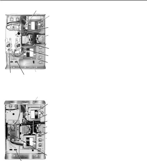
Fig. 7. Internal view of R8182H.
SAFETY SWITCH
RESET BUTTON
TRANSFORMER
FOR THERMOSTAT
CIRCUIT
AQUASTAT SWITCH
2K RELAY
1K RELAY
VOLTAGE BARRIER
TRANSFORMER
FOR CAD CELL
CIRCUIT
HIGH LIMIT
SETTING
CAD CELL LEADS (YELLOW)
M4531
Fig. 8. Internal view of R8182J.
INSTALLATION
When Installing this Product…
Read these instructions carefully. Failure to follow them could damage the product or cause a hazardous condition.
Check the ratings given in these instructions and on the product to be sure the product is suitable for your application.
Be sure the installer is a trained, experienced service technician.
After completing installation, use these instructions to check product operation.
 CAUTION
1.Disconnect the power supply before beginning installation to prevent electrical shock or equipment damage.
2.Be sure that the combustion chamber is clear of oil or oil vapor before starting burner.
3.Be sure that the ambient temperature at the element does not exceed 250°F (121°C).
IMPORTANT
Be sure that the sensing bulb fits snugly inside the immersion well and that the sensing bulb rests against the bottom of the immersion well. Refer to Fig. 3.
Mounting the R8182
Disconnect power supply.
Drain all water from boiler.
Most boilers are equipped with a tapping that allows horizontal mounting of immersion well where average temperature boiler water circulates freely. If no tapping is provided, prepare one.
Install immersion well or compression fitting (ordered separately) by threading immersion well into tapped hole.
For R8182D,E,F models:
a.Loosen immersion well clamp screw on side of R8182 case.
b.Insert bulb into immersion well until it bottoms.
c.If necessary, bend capillary tube to hold bulb against bottom of immersion well.
NOTE: Do not make sharp bends in the tubing. A sharp bend can break the tubing and cause a loss of fill. In models with an adjustable tubing length, pull the extra tubing out of the controller case.
d.Fit controller case onto immersion well so that immersion well clamp slides over flange of immersion well.
e.Securely tighten immersion well clamp screw.
For R8182H,J models:
a.Loosen the screw holding the hinged backplate to the controller case and swing the backplate away from the controller case.
b.Screw the backplate to a 4 by 4 inch junction box.
c.Insert bulb into immersion well until it bottoms.
d.If necessary, bend capillary tube to hold bulb against bottom of immersion well.
NOTE: Do not make sharp bends in the tubing. A sharp bend can break the tubing and cause a loss of fill. In models with an adjustable tubing length, pull the extra tubing out of the controller case.
e.Tighten immersion well screw over brass collar.
f.After wiring, swing the control against the backplate and refasten the screw.
Refill the boiler and check for water leakage.
3 |
69-0600—1 |
 Loading...