


N10010
N05010/N10010
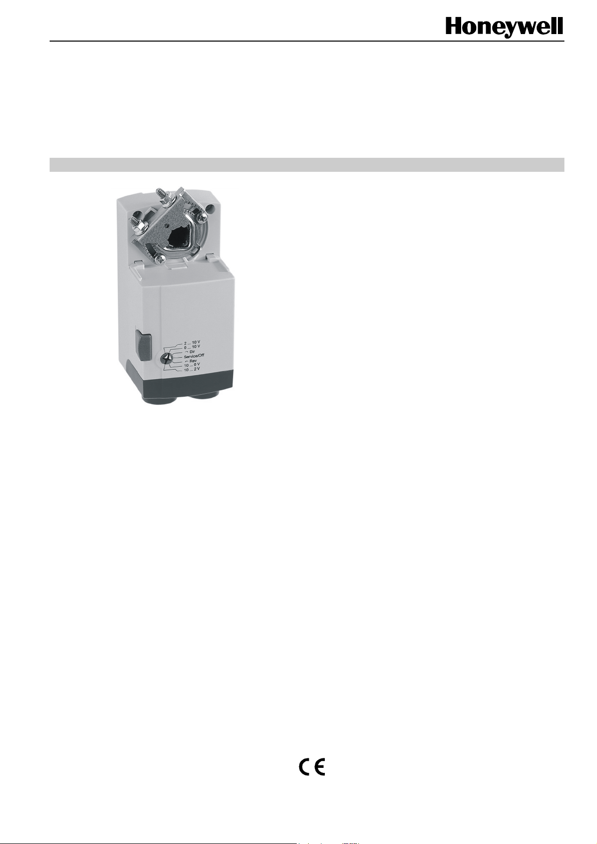
NON-SPRING RETURN DIRECT-COUPLED DAMPER ACTUATORS FOR
MODULATING AND FLOATING / 2-POSITION CONTROL
PRODUCT DATA
SPECIFICATIONS
Supply voltage 24 Vac/dc -15%/+20%, 50/60 Hz
Nominal voltage 24 Vac/dc, 50/60 Hz
All values stated hereinafter apply to operation under
nominal voltage conditions.
Power consumption
N05010 5 VA / 2 W
N10010 5 VA / 2 W
Control signal
Modulating 0...10 V
Floating/2-Position 24 Vac/dc
Ambient limits
Ambient operating limits -20...+60 °C (-5...+140 °F)
Ambient storage limits -30...+80 °C (-22...+176 °F)
Relative humidity 5...95%, non-condensing
Safety
GENERAL
This non-spring return direct-coupled damper actuator
provides modulating and floating/2-position control for:
• air dampers,
• VAV units,
• air handlers,
• ventilation flaps,
• louvers, and
• reliable control for air damper applications with up to 1 m
/ (5 Nm) and 2 m
friction-dependent).
2
(10 Nm) (seal-less damper blades; air
FEATURES
• Declutch for manual adjustment
• Adjustable mechanical end limits
• Removable access cover for direct wiring
• Mountable in any orientation
• Function selection switch for selecting modulating or
floating/2-position control
Protection standard IP54
Protection class II as per EN 60730-1
Overvoltage category II
Lifetime
Full strokes 60000
Repositions 1.5 million
Mounting
Round damper shaft 8...16 mm
Square damper shaft 6...13 mm; 45° steps
Shaft length min. 41 mm
2
End switches (when included)
Rating 5 A (resistive), 3 A (inductive)
Triggering points 5° / 85°
Torque rating 5 Nm / 10 Nm
Runtime for 90°
mod. (dc / 50/60 Hz ac) 90 sec
floating (dc / 60 Hz ac) 90 sec
floating (50 Hz ac) 110 sec
Rotation stroke 95° ± 3°
Dimensions see "Dimensions" on page 8
Weight (without cables) 450 g
Noise rating 35 dB(A) max. at 1 m
® U.S. Registered Trademark EN0B-0478GE51 R0408
Copyright © 2008 Honeywell Inc. • All rights reserved
N05010/N10010 DAMPER ACTUATORS FOR MODULATING AND FLOATING/2-POSITION CONTROL
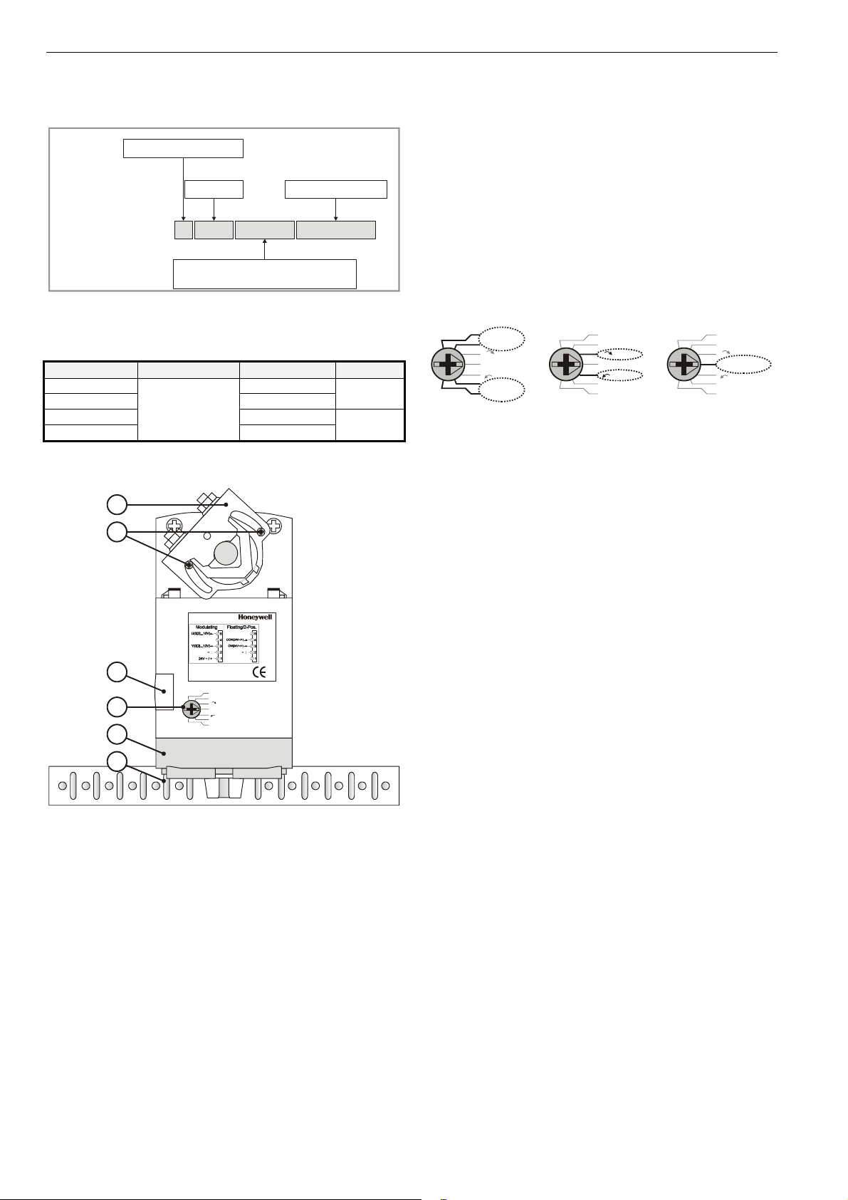
PRODUCT IDENTIFICATION SYSTEM
Contents of Package
The delivery package includes the actuator, parts 1 through 6
N = non-spring return
S = spring return
(see Fig. 2), plus two cable grommets and a spare cable
grommet.
05 = 5 Nm
10 = 10 Nm
equipped with two
end switches
RUN MODES
The function selection switch (see Fig. 3) can be used to
W
SmartAct
N
5
0
0-0
010 = modulating + floating
24 = 24 V floating + ON/OFF
230 = 230 V ON/OFF
S
+ ON/OFF
21
Fig. 1. Product Identification System
place the actuator into any one of three different modes:
• Service/Off;
• the floating/2-position run mode ("Dir" for CCW-closing
dampers or "Rev" for CW-closing dampers); and
• the modulating run mode.
modulating
MODELS
order no. supply voltage end switches torque
N05010 -N05010-SW2 2
N10010 -N10010-SW2
24 Vac/dc
2
BASIC FEATURES
1
2
N05010
3
2...10 V
0...10 V
Dir
4
5
6
Fig. 2. Setting units and control elements
Legend for Fig. 2:
1) Universal shaft adapter
2) Mechanical end limits
3) Declutch button
4) Function selection switch
5) Removable access cover
6) Anti-rotation bracket
Service/Off
Rev
10...0 V
10...2 V
5 Nm
10 Nm
Power-Off Behavior
If power is removed, the shaft adapter remains in position.
Service/Off
If the function selection switch is set to the "Service/Off"
position, then all rotary movement is cancelled, and all control
signals are ignored, thus allowing the actuator to be manually
operated safely.
Floating/2-Position Run Mode
Without Feedback Signal
If, however, the function selection switch has been set to one
of the two floating/2-position control settings – but the
actuator has not been wired for a feedback signal (see Fig. 12
and Fig. 13) – then as soon as operating power is applied, the
shaft adapter will run according to the control signals applied.
With Feedback Signal
If the function selection switch has been set to one of the two
floating/2-position control settings – and if the actuator has
been wired for a feedback signal (see Fig. 12 and Fig. 13) –
then as soon as operating power is applied, the shaft adapter
will likewise run first completely counterclockwise and then
completely clockwise (see also section "Adaption"), after
which it will run according to the control signals applied.
Modulating Run Mode
If the function selection switch has been set to one of the four
modulating control settings – and if the actuator is wired
correspondingly (see Fig. 11) – then as soon as operating
power is applied, the shaft adapter will run first completely
counterclockwise and then completely clockwise (see also
section "Adaption"), after which it will run according to the
control signals applied.
floating/2-position
2...10 V
0...10 V
Dir
Service/Off
Rev
10...0 V
10...2 V
2...10 V
0...10 V
Dir
Service/Off
Rev
10...0 V
10...2 V
Fig. 3. Function selection switch
Service/Off
2...10 V
0...10 V
Service/Off
Rev
10...0 V
10...2 V
Dir
EN0B-0478GE51 R0408
2
N05010/N10010 DAMPER ACTUATORS FOR MODULATING AND FLOATING/2-POSITION CONTROL
Table 1 describes, for the floating mode, the shaft adapter
behavior ("stops," rotates "CCW," or rotates "CW") in
dependence upon the control signals applied to terminals 3
and 4 and upon the function selection switch setting.
Table 2 describes, for the 2-position mode, the shaft adapter
behavior ("stops," rotates "CCW," or rotates "CW") in
dependence upon the control signals applied to terminals 3
and 4 and upon the function selection switch setting.
Table 1. Shaft adapter behavior in the floating mode
control signal at switch settings
terminal 3 terminal 4 0[2]...10 V Dir Service / Off Rev 10...0[2] V
open open
open 24 Vac/dc
24 Vac open
Table 2. Shaft adapter behavior in the 2-position mode
control signal at switch settings
terminal 3 terminal 4 0[2]...10 V Dir Service / Off Rev 10...0[2] V
24 Vac open
24 Vac 24 Vac/dc
Table 3. Shaft adapter behavior in the modulating mode
control signal at switch settings
terminal 3 terminal 4 0[2]...10 V Dir Service / Off Rev 10...0[2] V
open
< min. control signal plus 0.24 V
between min. control signal plus 0.24 V
and max. control signal minus 0.24 V
> max. control signal minus 0.24 V
open
24 Vac/dc
open
24 Vac/dc
open
24 Vac/dc
open
24 Vac/dc
Table 3 describes, for the modulating mode, the shaft adapter
behavior ("stops," rotates "totally CCW," rotates "totally CW,"
runs to "proportional" position, or runs to "50%" of max.
stroke) in dependence upon the control signals applied to
terminals 3 and 4 and upon the function selection switch
setting.
-- stops stops stops --
-- CCW stops CW --
-- CW stops CCW --
-- CW stops CCW --
-- CCW stops CW --
totally CCW -- stop -- totally CCW
50% -- stop -- 50%
totally CCW -- stop -- totally CW
50% -- stop -- 50%
proportional -- stop -- proportional
50% -- stop -- 50%
totally CW -- stop -- totally CCW
50% -- stop -- 50%
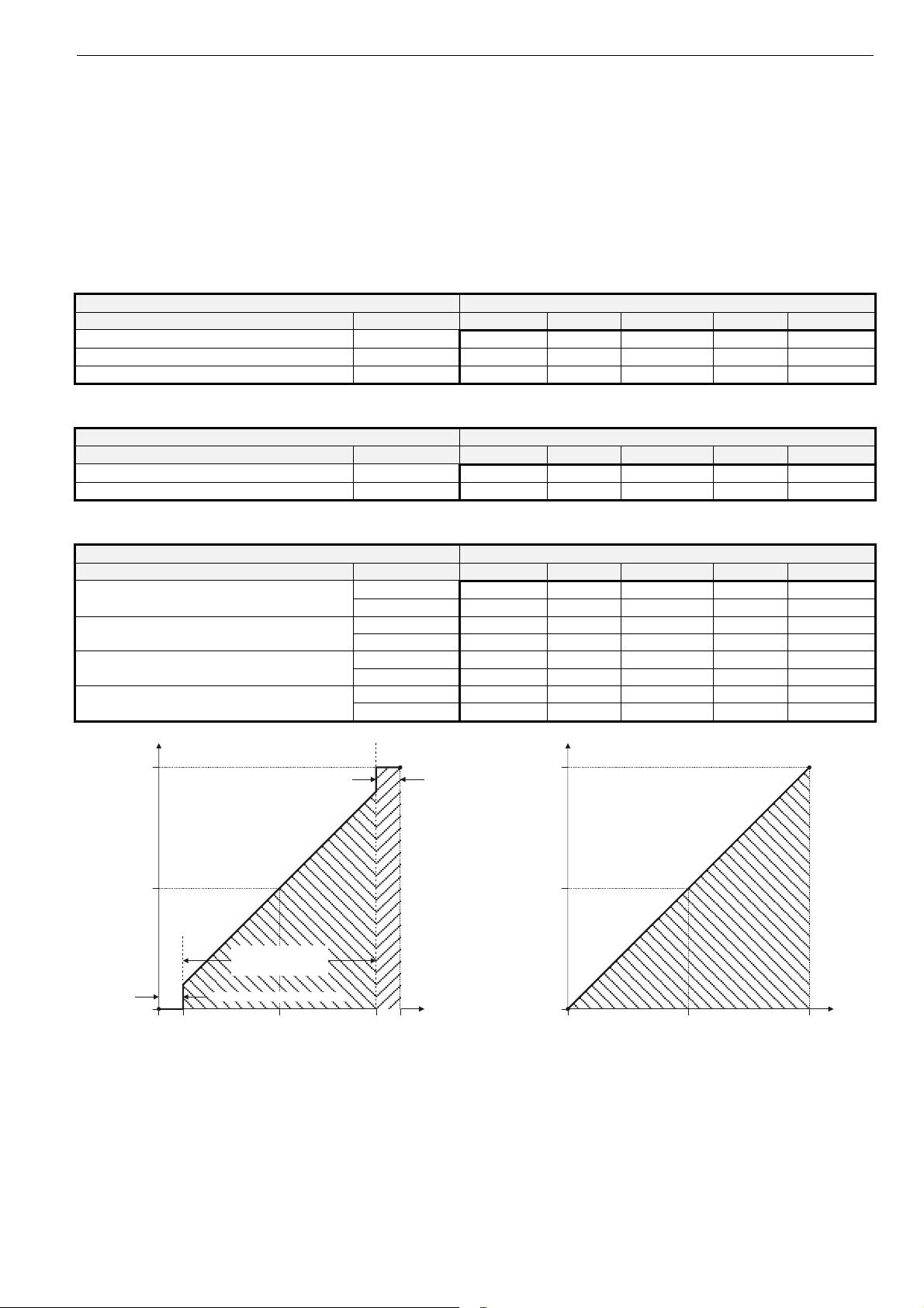
final position of shaft adapter (% of max. stroke)
100
50
0
upper dead band (9.76 to 10.0 V)
range of proportional
actuator movement
(0.24 to 9.76 V)
lower dead band (0 to 0.24 V)
00.24
control signal (V)
5.0 10.09.76
Fig. 4. Final shaft adapter position in dependence upon
control signal (example function selection switch setting
of 0...10 V)
100
50
0
0
current position of shaft adapter (% of max. stroke)
feedback signal (V)
510
Fig. 5. Feedback signal in dependence upon current
position of shaft adapter (example function selection
switch setting of 0...10 V)
3 EN0B-0478GE51 R0408
 Loading...