


 Loading...
IMAGETEAM™ 2020/5620
Retail Cordless System
|
|
|
|
|
|
|
|
|
|
|
4 |
|
|
|
|
|
|
|
|
|
|
0 |
|
|
|
|
|
|
|
|
|
|
|
/ |
|
ManualSystem |
|
|
|
|
|
|
|
|
3 |
|
|
|
|
|
|
|
|
1 |
|
|
|||
|
|
|
|
|
|
/ |
|
|
|
||
|
|
|
|
|
|
0 |
|
|
|
||
|
|
|
|
|
1 |
|
|
|
|
|
|
|
|
|
|
3 |
|
|
|
|
|
|
|
|
|
|
1 |
|
|
|
|
|
|
|
|
|
|
t |
|
|
|
|
|
|
|
|
|
|
f |
|
|
|
|
|
|
|
|
|
|
|
a |
|
|
|
|
|
|
|
|
|
|
Dr |
|
|
|
|
|
|
|
|
|
|
|
|
|
|
|
|
|
|
|
|
|
|
|
|
|
|
|
|
|
|
|
|
|
|
|

Disclaimer
Hand Held Products, Inc. d/b/a HHP (“HHP”) reserves the right to make changes in specifications and other information contained in this document without prior notice, and the reader should in all cases consult HHP to determine whether any such changes have been made. The information in this publication does not represent a commitment on the part of HHP.
HHP shall not be liable for technical or editorial errors or omissions contained herein; nor for incidental or consequential damages resulting from the furnishing, performance, or use of this material.
This document contains proprietary information which is protected by copyright. All rights are reserved. No part of this document may be photocopied, reproduced, or translated into another language without the prior written consent of HHP.
© 2004 Hand Held Products, Inc. All rights reserved.
Web Address: www.HHP.com
Microsoft Pocket PC 2002, Windows, Windows NT, Windows 2000, Windows ME, Windows XP, ActiveSync, Outlook, and the Windows logo are trademarks or registered trademarks of Microsoft Corporation.
The Bluetooth trademarks are owned by Bluetooth SIG, Inc., U.S.A.

Statement of Agency Compliance
The IT2020/IT5620 system meets or exceeds the requirements of all applicable standards organizations for safe operation. However, as with any electrical equipment, the best way to ensure safe operation is to operate them according to the agency guidelines that follow. Please read these guidelines carefully before using your IT2020/IT5620 system.
Regulatory and Safety Approvals for the IT2020/IT5620
Parameter |
Specification |
|
|
USA |
FCC Part 15, Class B |
Canada |
ICES-003 |
European Community |
EN 55022 (CISPR 22) Class B |
|
EN60950 |
|
EN60825-1 |
|
EN55024:1998 |
|
|
FCC Class B Compliance Statement
This device complies with part 15 of the FCC Rules. Operation is subject to the following two conditions:
1.This device may not cause harmful interference.
2.This device must accept any interference received, including interference that may cause undesired operation.
This equipment has been tested and found to comply with the limits for a Class B digital device pursuant to part 15 of the FCC Rules. These limits are designed to provide reasonable protection against harmful interference in a residential installation. This equipment generates, uses, and can radiate radio frequency energy and, if not installed and used in accordance with the instructions, may cause harmful interference to radio communications. If this equipment does cause harmful interference to radio or television reception, which can be determined by turning the equipment off and on, the user is encouraged to try to correct the interference by one or more of the following measures:
•Reorient or relocate the receiving antenna.
•Increase the separation between the equipment and receiver.
•Connect the equipment into an outlet on a circuit different from that to which the receiver is connected.
•Consult the dealer or an experienced radio or television technician for help.

If necessary, the user should consult the dealer or an experienced radio/ television technician for additional suggestions. The user may find the following booklet helpful: “Something About Interference.” This is available at FCC local regional offices. Hand Held Products, Inc. is not responsible for any radio or television interference caused by unauthorized modifications of this equipment or the substitution or attachment of connecting cables and equipment other than those specified by Hand Held Products, Inc. The correction is the responsibility of the user. Use only shielded data cables with this system.
In accordance with FCC 15.21, changes or modifications not expressly approved by the party responsible for compliance could void the user’s authority to operate the equipment.
This device and its antenna must not be co-located or operating in conjunction with any other antenna or transmitter. To maintain
!compliance with FCC RF exposure guidelines for body-worn operation, do not use accessories that contain metallic components and ensure that the device is at least 15mm (0.6 inches) from the body.
Canadian Compliance
This Class B digital apparatus compiles with Canadian ICES-003. Operation is subject to the following two conditions:
1.This device may not cause harmful interference.
2.This device must accept any interference received, including interference that may cause undesired operation.
3.To prevent radio interference to the licensed service, this device is intended to be operated indoors and away from windows to provide maximum shielding. Equipment (or its transmit antenna) that is installed outdoors is subject to licensing.
Cet appareil numérique de la Classe B est conforme à la norme NMB-003 du Canada.
CE Compliance
 The CE mark on the product indicates that the system has been tested to and conforms with the provisions noted within the 89/336/EEC Electromagnetic Compatibility Directive and the 73/23/EEC Low Voltage Directive.
For CE-related inquiries, please contact: Hand Held Products, Inc. Nijverheidsweg 9
5627 BT Eindhoven The Netherlands

HHP shall not be liable for use of our product with equipment (i.e., power supplies, personal computers, etc.) that is not CE marked and does not comply with the Low Voltage Directive.
Regulatory Approvals for Bluetooth Radio Devices
RF devices are designed to comply with the most current applicable standards on safe levels of RF energy developed by the Institute of Electrical and Electronics Engineers (IEEE) and the American National Standards Institute (ANSI) and have been recommended for adoption by the Federal Communications Commission (FCC).
Parameter |
Specification |
|
|
RF Approvals |
|
U.S.A. |
FCC Part 15.247 |
Canada |
RSS 210 |
|
|
Bluetooth Radio Device R&TTE Compliance Statement
The IT2020 and IT5620 are in conformity with all essential requirements of the R&TTE Directive (1999/5/EC). This equipment has been assessed to the following standards:
Parameter |
Specification |
|
|
R&TTE |
EN 300 328-2:2000 |
|
EN 301 489-1 (2002-08) |
|
EN 301 489-17 (2002-08) |
|
EN 60950:2000 |
|
EN 50361:2001 |
|
|
This product is marked with  in accordance with the Class II product requirements specified in the R&TTE Directive, 1999/5/EC.
The equipment is intended for use throughout the European Community.
Bluetooth Qualified Product
Bluetooth Identifier:

UL and cUL Statement
UL listed UL1950 and CSA 22.2 No.950. cUL listed UL1950 and CSA 22.2 No 950.
TÜV Statement
TÜV or GS marked to EN60950 and EN60825-1.
C-Tick Statement
Conforms to AS/NZS 3548. C-Tick number: N10410.
Mexico
 Certified
Patents
Please refer to the IT5620 packaging for patent information.
Solids and Water Protection
The IT5620 has a rating of IP41, immunity of foreign particles and dripping water.
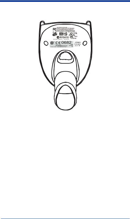
Required Safety Labels
IT5620

IT2020
|
' |
|
|
' |
|
|
Hand Held Products, Inc. |
|
|
Skaneateles Falls, NY 13153 |
|
|
www.hhp.com |
|
|
I.T.E. |
|
|
ACCESSORY |
|
|
7D21 |
|
US and Foreign Patents Pending |
E153740 |
|
0682 |
||
FCC ID: HD5MX2702B |
||
Canada IC1693BMX2702B |
||
|
"Made in China" |

Table of Contents
Chapter 1 - Getting Started
IMAGETEAM 5620............................................................. |
1-1 |
About This Manual............................................................... |
1-1 |
Unpacking the System .......................................................... |
1-2 |
Models .................................................................................. |
1-2 |
Cordless System: Main Components.................................... |
1-3 |
About the Battery.................................................................. |
1-3 |
Proper Disposal of the Battery ....................................... |
1-4 |
Base Charge Mode................................................................ |
1-5 |
Linking Scanner to Base....................................................... |
1-6 |
Unlinking the Scanner.................................................... |
1-6 |
Link Modes........................................................................... |
1-6 |
Locked Link Mode......................................................... |
1-7 |
Open Link Mode ............................................................ |
1-7 |
Out-of-Range Alarm............................................................. |
1-8 |
Duration.......................................................................... |
1-8 |
Alarm Sound Type ......................................................... |
1-8 |
Data Accumulation Mode..................................................... |
1-9 |
Beeper and LED Sequences and Meaning............................ |
1-9 |
IT5620 LED Sequences and Meaning ........................... |
1-9 |
IT2020 LED Sequences and Meaning ........................... |
1-9 |
Basic Operation of the Cordless System ............................ |
1-10 |
System Conditions ....................................................... |
1-11 |
Communication Between the Cordless System and the Host |
|
1-11 |
|
Connecting the Base When Powered by Host |
|
(Keyboard Wedge)........................................................... |
1-12 |
Reading Techniques............................................................ |
1-13 |
Resetting the Standard Product Defaults ............................ |
1-14 |
Plug and Play ...................................................................... |
1-14 |
Keyboard Wedge Connection............................................. |
1-14 |
Laptop Direct Connect ................................................. |
1-15 |
RS-232.......................................................................... |
1-15 |
Wand Emulation Plug & Play...................................... |
1-15 |
IBM 4683 Ports 5B, 9B, and 17 Interface .......................... |
1-17 |
i

Connecting the Base with USB........................................... |
1-18 |
IBM SurePos ................................................................ |
1-19 |
USB PC or Macintosh Keyboard.................................. |
1-19 |
USB HID ...................................................................... |
1-20 |
USB Com Port Emulation ............................................ |
1-20 |
Connecting the Base with Serial Wedge............................. |
1-21 |
Chapter 2 - Terminal Interfaces |
|
Terminal ID........................................................................... |
2-1 |
Supported Terminals ............................................................. |
2-2 |
Keyboard Country................................................................. |
2-4 |
Keyboard Style...................................................................... |
2-5 |
Keyboard Modifiers .............................................................. |
2-6 |
Connecting the Base with RS-232 Serial Port ...................... |
2-7 |
RS-232 Baud Rate .......................................................... |
2-8 |
RS-232 Word Length: Data Bits, Stop Bits, and Parity . 2-9 |
|
RS-232 Handshaking.................................................... |
2-10 |
Host ACK Selection ..................................................... |
2-10 |
Host ACK Enable ......................................................... |
2-11 |
Wand Emulation.................................................................. |
2-13 |
Wand Emulation Connection........................................ |
2-13 |
Wand Emulation Transmission Rate ............................ |
2-14 |
Wand Emulation Polarity ............................................. |
2-14 |
Wand Emulation Idle.................................................... |
2-15 |
Wand Emulation Data Block Size ................................ |
2-15 |
Wand Emulation Delay Between Blocks ..................... |
2-15 |
Wand Emulation Overall Checksum ............................ |
2-16 |
Chapter 3 - Output |
|
Good Read Indicators............................................................ |
3-1 |
Beeper – Good Read....................................................... |
3-1 |
Beeper Volume – Good Read......................................... |
3-1 |
Beeper Pitch – Good Read.............................................. |
3-2 |
Beeper Duration – Good Read........................................ |
3-2 |
LED – Good Read .......................................................... |
3-2 |
Number of Beeps – Good Read...................................... |
3-3 |
ii
Good Read Delay .................................................................. |
3-3 |
User-Specified Good Read Delay................................... |
3-3 |
Scanner Trigger Modes ......................................................... |
3-4 |
Manual/Serial Trigger, Low Power ................................ |
3-4 |
Automatic Trigger........................................................... |
3-5 |
Presentation Mode .......................................................... |
3-5 |
Hands Free Time-Out............................................................ |
3-5 |
Reread Delay ......................................................................... |
3-6 |
User-Specified Reread Delay.......................................... |
3-6 |
Centering Window ................................................................ |
3-7 |
Output Sequence Overview................................................... |
3-8 |
Output Sequence Editor .................................................. |
3-9 |
Require Output Sequence ............................................... |
3-9 |
Multiple Symbols ................................................................ |
3-12 |
No Read............................................................................... |
3-12 |
Video Reverse ..................................................................... |
3-12 |
Chapter 4 - Data Editing |
|
Prefix/Suffix Overview ......................................................... |
4-1 |
To Add a Prefix or Suffix: ............................................. |
4-2 |
To Clear One or All Prefixes or Suffixes: ...................... |
4-3 |
To Add a Carriage Return Suffix to all Symbologies..... |
4-3 |
Prefix Selections ............................................................. |
4-3 |
Suffix Selections ............................................................. |
4-4 |
Function Code Transmit ................................................. |
4-4 |
Intercharacter, Interfunction, and Intermessage Delays........ |
4-4 |
Intercharacter Delay........................................................ |
4-5 |
User Specified Intercharacter Delay ............................... |
4-5 |
Interfunction Delay ......................................................... |
4-6 |
Intermessage Delay......................................................... |
4-6 |
iii

Chapter 5 - Data Formatting
Data Format Editor Introduction........................................... |
5-1 |
To Add a Data Format.................................................... |
5-1 |
Other Programming Selections....................................... |
5-2 |
Data Format Editor Commands...................................... |
5-2 |
Data Format Editor ......................................................... |
5-4 |
Data Formatter................................................................ |
5-5 |
Alternate Data Formats................................................... |
5-5 |
Chapter 6 - Symbologies |
|
Introduction ........................................................................... |
6-1 |
All Symbologies.................................................................... |
6-1 |
Message Length .................................................................... |
6-2 |
Codabar ................................................................................. |
6-3 |
Codabar Start/Stop Characters....................................... |
6-3 |
Codabar Check Character............................................... |
6-3 |
Codabar Concatenation................................................... |
6-4 |
Codabar Message Length ............................................... |
6-5 |
Code 39 ................................................................................. |
6-5 |
Code 39 Start/Stop Characters....................................... |
6-5 |
Code 39 Check Character ............................................... |
6-6 |
Code 39 Message Length ............................................... |
6-6 |
Code 39 Append ............................................................. |
6-7 |
Code 32 Pharmaceutical (PARAF)................................. |
6-7 |
Full ASCII ...................................................................... |
6-8 |
Code 39 Code Page......................................................... |
6-9 |
Interleaved 2 of 5 .................................................................. |
6-9 |
Check Digit..................................................................... |
6-9 |
Interleaved 2 of 5 Message Length............................... |
6-10 |
Code 93 ............................................................................... |
6-11 |
Code 93 Message Length ............................................. |
6-11 |
Code 93 Code Page....................................................... |
6-11 |
Code 2 of 5 .......................................................................... |
6-12 |
Code 2 of 5 Message Length ........................................ |
6-12 |
IATA Code 2 of 5 Message Length.............................. |
6-13 |
iv

Matrix 2 of 5........................................................................ |
6-13 |
Matrix 2 of 5 Message Length...................................... |
6-14 |
Code 11................................................................................ |
6-14 |
Check Digits Required.................................................. |
6-14 |
Code 11 Message Length.............................................. |
6-15 |
Code 128.............................................................................. |
6-15 |
ISBT 128 Concatenation............................................... |
6-16 |
Code 128 Message Length............................................ |
6-16 |
Code 128 Code Page..................................................... |
6-16 |
Code 128 Function Code Transmit............................... |
6-17 |
Telepen ................................................................................ |
6-17 |
Telepen Output ............................................................. |
6-17 |
Telepen Message Length .............................................. |
6-18 |
UPC A ................................................................................. |
6-18 |
UPC A Check Digit ...................................................... |
6-18 |
UPC A Number System................................................ |
6-19 |
UPC A Addenda ........................................................... |
6-19 |
UPC A Addenda Required............................................ |
6-19 |
UPC A Addenda Separator ........................................... |
6-20 |
UPC-A/EAN-13 with Extended Coupon Code ................... |
6-20 |
UPC E0 and UPC E1........................................................... |
6-21 |
UPC E0 and UPC E1 Expand ....................................... |
6-21 |
UPC E0 and UPC E1 Addenda Required ..................... |
6-21 |
UPC E0 and UPC E1 Addenda Separator .................... |
6-22 |
UPC E0 Check Digit..................................................... |
6-22 |
UPC E0 Number System .............................................. |
6-22 |
UPC E0 Addenda.......................................................... |
6-23 |
EAN/JAN 13 ....................................................................... |
6-23 |
EAN/JAN 13 Check Digit ............................................ |
6-23 |
EAN/JAN 13 Addenda ................................................. |
6-24 |
EAN/JAN 13 Addenda Required.................................. |
6-24 |
EAN/JAN 13 Addenda Separator ................................. |
6-24 |
ISBN Translate ............................................................. |
6-25 |
v

EAN/JAN 8 ......................................................................... |
6-25 |
EAN/JAN 8 Check Digit .............................................. |
6-25 |
EAN/JAN 8 Addenda ................................................... |
6-26 |
EAN/JAN 8 Addenda Required ................................... |
6-26 |
EAN/JAN 8 Addenda Separator................................... |
6-26 |
MSI...................................................................................... |
6-27 |
MSI Check Character ................................................... |
6-27 |
MSI Message Length.................................................... |
6-28 |
Plessey Code ....................................................................... |
6-28 |
Plessey Message Length............................................... |
6-28 |
RSS Limited........................................................................ |
6-29 |
RSS Expanded..................................................................... |
6-30 |
RSS Expanded Message Length................................... |
6-30 |
EAN•UCC Emulation ......................................................... |
6-30 |
China Post Code.................................................................. |
6-31 |
Korea Post Code.................................................................. |
6-32 |
Korea Post Message Length ......................................... |
6-32 |
PosiCode A and B ............................................................... |
6-33 |
PosiCode Message Length............................................ |
6-33 |
Codablock F ........................................................................ |
6-34 |
Codablock F Message Length ...................................... |
6-34 |
Code 16K ............................................................................ |
6-35 |
Code 16K Message Length........................................... |
6-35 |
Code 49 ............................................................................... |
6-36 |
Code 49 Message Length ............................................. |
6-36 |
Chapter 7 - Interface Keys |
|
Keyboard Function Relationships......................................... |
7-1 |
Supported Interface Keys...................................................... |
7-3 |
Chapter 8 - Utilities |
|
To Add a Test Code I.D. Prefix to All Symbologies ............ |
8-1 |
Reset Scanner ........................................................................ |
8-1 |
Show Software Revision ....................................................... |
8-1 |
Show Data Format................................................................. |
8-1 |
Resetting the Standard Product Defaults............................... |
8-2 |
vi

Temporary Visual Menu 2003 Configuration ....................... |
8-2 |
Chapter 9 - Visual Menu 2003 |
|
Visual Menu 2003 Introduction ............................................ |
9-1 |
Installing Visual Menu 2003 from the Web ................... |
9-1 |
Chapter 10 - Serial Programming Commands |
|
Conventions......................................................................... |
10-1 |
Menu Command Syntax...................................................... |
10-1 |
Query Commands ......................................................... |
10-2 |
Concatenation of Multiple Commands ......................... |
10-2 |
Responses...................................................................... |
10-2 |
Examples of Query Commands .................................... |
10-3 |
Trigger Commands.............................................................. |
10-4 |
Resetting the Standard Product Defaults............................. |
10-4 |
Menu Commands ................................................................ |
10-5 |
Chapter 11 - Product Specifications |
|
IMAGETEAM 5620 Product Specifications ...................... |
11-1 |
IMAGETEAM 2020 Product Specifications ...................... |
11-2 |
IMAGETEAM 5620 Depth of Field ................................... |
11-3 |
Chapter 12 - Maintenance |
|
Maintenance ........................................................................ |
12-1 |
Cleaning the Scanner’s Window................................... |
12-1 |
Inspecting Cords and Connectors ................................. |
12-1 |
Replacing the IT2020 Interface Cable:......................... |
12-2 |
Troubleshooting Base.......................................................... |
12-2 |
Chapter 13 - Customer Support |
|
Obtaining Factory Service................................................... |
13-1 |
Technical Assistance ........................................................... |
13-2 |
Limited Warranty ................................................................ |
13-2 |
vii

Appendix A
Symbology Chart ................................................................. |
A-1 |
ASCII Conversion Chart (Code Page 1252) ........................ |
A-2 |
Code Page Mapping of Printed Bar Codes .......................... |
A-4 |
viii

1
G e t t in g S t a r t e d
IMAGETEAM 5620
The IMAGETEAM 5620 cordless scanning system consists of one IT2020 base and one IT5620 Cordless Linear Imager. The IT5620 marks a new performance
level for hand held scanners. The IT5620 is powered by HHP’s AdaptusTM Imaging Technology. The performance of Adaptus technology delivers aggressive read rates and depths of field on 1D codes.
Designed for today’s demanding retail and commercial environments, the IT5620 offers a superior reading range, durability, and the ability to read poor quality bar codes. Linear imaging technology is defined by a bright and sharply focused aiming line, high resolution imaging, and fast reading speed. The IT5620 is comfortable to hold, easy to use, rugged, and excellent for retail applications, as well as for all general scanning applications.
The cordless system is an economical, durable solution for a wide variety of portable data collection applications. The cordless system features:
•a tough, ergonomic thermoplastic housing for comfort and durability.
•an advanced two-way spread-spectrum radio, Bluetooth® wireless technology
•a wide range of interfaces that are compatible with many POS, keyboard wedge, wand emulation, RS-232 terminals, USB, and legacy decoders.
•visible and audible feedback for confirmation of a successful decode.
•a rechargeable battery designed to operate through a whole work day.
The cordless system can be programmed for many communication parameters and input/output protocols compatible to the host, as well as advanced data editing and formatting.
About This Manual
This manual contains information to help you set up, operate, and program the cordless system. Product specifications, connector pinouts, a troubleshooting guide, and customer support information are also provided.
HHP’s bar code scanners are factory programmed for the most common terminal and communications settings. If you need to change these settings, programming is accomplished by scanning the bar codes in this guide.
An asterisk (*) next to an option indicates the default setting.
This section contains the following information:
•Unpacking the System
•Cordless System Main Components
•Battery and Charging Information
•Linking the Scanner to the Base
•Beeper and LED Sequences and Meaning
•Basic Operation of the Cordless System
IMAGETEAM™ 2020/5620 System Manual |
1 - 1 |

•Communication Between the Cordless System and the Host
•Connection of the Base to an Interface
Unpacking the System
After you open the shipping carton containing the product, take the following steps:
•Check to make sure everything you ordered is present.
•Save the shipping container for later storage or shipping.
•Check for damage during shipment. Report damage immediately to the carrier who delivered the carton.
Models
Models |
Description |
|
|
|
|
2020-5 |
Base: Keyboard wedge, TTL level 232, TTL level 232 |
|
serial wedge, IBM 4683, wand emulation, USB keyboard, |
|
USB HID, USB retail (IBM SurePOS) |
|
|
2020-CB |
Base with charger only (no host interfaces) |
|
|
5620SR0C0 |
Cordless Linear Scanner |
|
|
1 - 2 |
IMAGETEAM™ 2020/5620 System Manual |
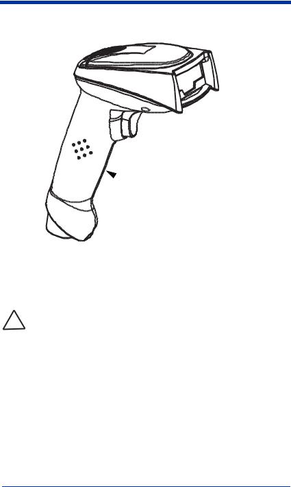
Cordless System: Main Components
Battery Contained in Handle
About the Battery
Use only the Li-ion battery packs provided by HHP. The use of any
!battery pack not sold by HHP will void your warranty and may result in damage to your unit.
Power is supplied to the cordless scanner by a rechargeable battery that is integrated in the scanner handle. Each scanner is shipped with a battery. (See Product Specifications beginning on page 11-1.)
Charging Information
The battery is designed to charge while the scanner is positioned in the cordless base unit. Refer to "IT2020 LED Sequences and Meaning" on page 1-9 for an interpretation of the Charge Status indicators.
•Place the scanner in the base that is connected to an appropriate power supply.
IMAGETEAM™ 2020/5620 System Manual |
1 - 3 |

Battery Recommendations
•Batteries are shipped approximately 30% to 60% charged and should be fully charged for maximum charge capacity.
•The battery is a lithium ion cell and can be used without a full charge, as well as can be charged without fully discharging, without impacting the battery life. There is no need to perform any charge/discharge conditioning on this cell type battery.
•Do not disassemble the battery. There are no user-serviceable parts in the battery.
•Keep the base connected to power when the host is not in use.
•Replace a defective battery immediately since it could damage the IT5620.
•Don’t short-circuit a battery or throw it into a fire. It can explode and cause severe personal injury.
•Although your battery can be recharged many times, it will eventually be depleted. Replace it after the battery is unable to hold an adequate charge.
•If you are not sure if the battery or charger is working properly, send it to HHP or an authorized HHP service center for inspection.
Proper Disposal of the Battery
When the battery has reached the end of its useful life, the battery should be disposed of by a qualified recycler or hazardous materials handler. Do not incinerate the battery or dispose of the battery with general waste materials. You may send batteries to HHP (postage paid). The shipper is responsible for complying with all federal, state, and local laws and regulations related to the packing, labeling, manifesting, and shipping of spent batteries. Contact the Product Service
Department (see page 11-1) for recycling or disposal information. Since you may find that your cost of returning the batteries significant, it may be more cost effective to locate a local recycle/disposal company.
1 - 4 |
IMAGETEAM™ 2020/5620 System Manual |
Base Charge Mode
In order for the battery to be charged, there must be enough voltage for the circuitry to work. There are three conditions during which power can be supplied to the base:
Condition 1: 9VDC power supply connected to the barrel connector Condition 2: 12VDC host power source only
Condition 3: 5VDC host power source only
The chart below describes each selection by condition.
|
Condition 1 |
Condition 2 |
Condition 3 |
|
|
|
|
Automatic |
Fast Charge |
Slow Charge |
No Charge |
|
|
|
|
Full Charge Rate |
Fast Charge |
Fast Charge |
No Charge |
|
|
|
|
Low Charge Rate |
Slow Charge |
Slow Charge |
No Charge |
|
|
|
|
Battery Charge Off |
No Charge |
No Charge |
No Charge |
|
|
|
|
Using a slow charge rate draws less current (power) from the input power source when the battery is mostly discharged.
Scan the appropriate bar code for your application. Default = Automatic.
* Automatic
Full Charge Rate
Low Charge Rate
Battery Charge Off
IMAGETEAM™ 2020/5620 System Manual |
1 - 5 |

Linking Scanner to Base
When newly shipped or defaulted to factory settings, the base and scanner are not linked. Once the scanner is placed into the base, the software automatically links the scanner and the base. If the scanner and base have previously been linked, you do not receive any feedback. If this is the first time that the scanner and base are linked, both devices emit a short chirp when their radios link.
IT5620 Imager
Green LED 

Red LED
IT2020 Cordless Base
1.Provide power to the base.
2.Place the IT5620 into the base. The scanner and base link.
3.To determine if your cordless system is set up correctly, scan one of the sample bar codes in the back of this manual. If the scanner provides a single good read beep and the green LED lights, the scanner has successfully linked to the base. If you receive a triple error beep and the red LED lights, the scanner has not linked to the base.
Unlinking the Scanner
If the base has a scanner linked to it, that scanner must be unlinked before a new scanner can be linked. Once the previous scanner is unlinked, it will no longer communicate with the base. To unlink a scanner from the base, scan the Unlink Scanner bar code below.
Unlink Scanner
Link Modes
There are two link modes to accommodate different applications: Locked Link Mode and Open Link Mode. Scan the appropriate bar codes included in the Open Link and Locked Link Mode explanations that follow to switch from one mode to another. Default = Locked Link Mode.
1 - 6 |
IMAGETEAM™ 2020/5620 System Manual |

Locked Link Mode
If you link a scanner to a base using the Locked Link Mode, this blocks other scanners from being linked if they are inadvertently placed into the base. If you do place a different scanner into the base, it will charge the scanner, but the scanner will not be linked.
* Locked Link Mode
To use a different scanner, you need to remove the original scanner by scanning the Unlink Scanner bar code. (See "Unlinking the Scanner" on page 1-6.)
If you need to replace a broken or lost scanner that is linked to a base, scan the Override Locked Scanner bar code below and place that scanner in the base. The locked link will be overridden; the broken or lost scanner’s link with the base will be removed, and the new scanner will be linked.
Override Locked Scanner
Open Link Mode
When newly shipped or defaulted to factory settings, the base and scanner are not linked. By placing a scanner into the base, they establish a link. Placing a different scanner into the base establishes a new link and the old scanner is unlinked. Each time a scanner is placed into the base, it becomes the linked scanner; the old scanner is unlinked.
Open Link Mode
IMAGETEAM™ 2020/5620 System Manual |
1 - 7 |

Out-of-Range Alarm
Duration
If your scanner is out range of the base, an alarm sounds from both your base and scanner if they are programmed to emit an alarm. To activate the alarm options for the scanner or the base and to set the alarm duration, scan the appropriate bar code below and then set the time-out duration (from 0-3000 seconds) by scanning digits on the Programming Chart inside the back cover, then scanning Save. Default = 0 sec (no alarm).
Base Duration Alarm
Scanner Duration Alarm
Note: If you are out of range when you scan a bar code, you will receive an error beep even if you do not have the alarm set. You receive the error beep since the data could not be communicated to the base or the host.
Alarm Sound Type
If you have set the out-of-range alarm enabled, you may change the alarm type for the scanner or base by scanning the appropriate bar code below and then scanning a digit (0-7) bar code and the Save bar code on the Programming Chart inside the back cover of this manual. Default = 0. Set the sound type to fit your application.
Base Alarm Type
Scanner Alarm Type
1 - 8 |
IMAGETEAM™ 2020/5620 System Manual |

Data Accumulation Mode
Scan the bar codes below to turn data accumulation (batch) mode on and off. If data accumulation mode is on, bar code data is stored when the scanner is out of range of the base and transmitted once the scanner is back in range.
Data Accumulation Mode On
* Data Accumulation Mode Off
Beeper and LED Sequences and Meaning
The IT5620 contains LEDs on the top of the unit to indicate its power up, communication, and battery status. Simply stated, red LED = error; green LED = success of any type. The unit’s audible indicators have meaning as well: 3 beeps = error; 2 beeps = menu change; 1 beep = all other successes.
The table below lists the indication and cause of the LED illumination and beeps for the IT5620.
IT5620 LED Sequences and Meaning
LED Indication |
Beeper Indication |
Cause |
|
|
|
|
|
|
|
|
|
Normal Operation |
|
|
|
Red Flash |
None |
Battery low |
|
|
|
|
|
Green Flash |
1 beep |
Successful communication |
|
or linking |
|||
|
|
||
|
|
|
|
Red, blinking |
3 beeps |
Failed communication |
|
|
|
|
|
Menu Operation |
|
|
|
|
|
|
|
Green Flash |
2 beeps |
Successful menu change |
|
|
|
|
|
Red, blinking |
3 beeps |
Unsuccessful menu change |
|
|
|
|
IT2020 LED Sequences and Meaning
The base contains a red LED that indicates the status of the unit and verifies its communication with the host system and a green LED that indicates scanner battery charge condition.
IMAGETEAM™ 2020/5620 System Manual |
1 - 9 |

The tables below list the indication and cause of the LED illumination and beeps for the IT2020.
System Condition |
System Status Indicator (Red LED) |
|
|
Power On/System Idle |
LED is on |
|
|
Power On/Diagnostic Error |
Blink LED for long duration, pulsing indefinitely |
|
|
|
Blink LED for short duration in multiple pulses. Occurs |
Receiving Data |
while transferring data to/from the RF module or the Host |
|
port. |
|
|
Note: Charging only occurs with external power applied to the IT2020 or 12 volt Host power.
Charge Condition |
Charge Status Indicator (Green LED) |
|
|
Scanner inserted into base |
Three flashes |
|
|
>80% charged |
On continuously |
|
|
30% to 80% charged |
Slow flash, 1 second on, 1 second off |
|
|
<30% charged |
Fast flash, 300 mSec on, 300 mSec off |
|
|
Basic Operation of the Cordless System
Cordless Base
The cordless base provides the link between the cordless scanner and the host system. The base contains an interface assembly and an RF communication module. The RF communication module performs the data exchange between the cordless scanner and the interface assembly. The control assembly coordinates the central interface activities including: transmitting/receiving commands and data to/from the host system, performing software activities (parameter menuing, visual indicator support, power-on diagnostics), and data translation required for the host system.
The base also is the scanner battery charger with the external 9VDC power source applied. Once you place the scanner into base, the base green LED responds according to the Charge Status Indicator table above.
The base can be powered by the Host (parasitic power mode). If the base is in parasitic power mode without the 9VDC power source, the base will still function, but will not charge the battery.
RF (Radio Frequency) Module Operation
The cordless system uses a state-of-the-art two-way Bluetooth radio to transmit and receive data between the scanner and the base. Designed for point-to-point and multipoint-to-single point applications, the radio operates using a license free ISM band, which sends relatively small data packets at a fast data rate over
1 - 10 |
IMAGETEAM™ 2020/5620 System Manual |

a radio signal with randomly changing frequencies, makes the cordless system highly responsive to a wide variety of data collection applications and resistant to noisy RF environments. Bluetooth Class 2 power level provides range of 33 feet (10m) depending on the environment.
Cordless Scanner
The cordless scanner enables fast and accurate bar code scanning using a noncontact linear imager.
The scanner is comprised of a linear imager, a decode/control assembly, and an RF communication module. The scan engine performs the bar code image illumination and sensing. The decode/control assembly coordinates the central communication activities including: capturing and decoding the bar code image data, performing software activities (parameter menuing, visual indicator support, low battery indication), and data translation required for the host system. The RF communication module performs the data exchange between the scanner and the base.
System Conditions
The components of the cordless system interact in specific ways as you associate a scanner to a base, as you move a scanner out of range, bring a scanner back in range, or swap scanners between two cordless systems. The following information explains the cordless system operating conditions.
Linking Process
Once a scanner is placed into the base, the scanner’s battery charge status is checked, and software automatically detects the scanner and links it to the base if another scanner is not already linked.
Scanner is Out of Range
The cordless scanner is in communication with its base, even when it is not transmitting bar code data. Whenever the scanner can’t communicate with the base for a few seconds, it is out of range. If the scanner is out of range and you scan a bar code, the scanner issues a triple beep and your scanner and base sounds an alarm if your scanner is programmed to emit an alarm.
Scanner is Moved Back Into Range
The scanner re-links if the scanner or the base have been reset or out of range. If the scanner re-links, you will hear a single chirp when the re-linking process (uploading of the parameter table) is complete.
Communication Between the Cordless System and the Host
The cordless scanner provides immediate feedback in the form of a “good read” indication (a green LED on the scanner and an audible beep) after a bar code is scanned correctly and the base has acknowledged receiving the data. This is possible since the cordless system provides two-way communication between the scanner and the base.
IMAGETEAM™ 2020/5620 System Manual |
1 - 11 |
When data is scanned, the data is sent to the host system via the base unit. Confirmation from the host system or the base indicates that the data sent was received by the host. The cordless scanner recognizes data acknowledgement (ACK) from the base unit. If it cannot be determined that the data has been properly sent to the base, the scanner issues an error indication. You must then check to see if the scanned data was received by the host system.
1) Good Read
3) Base sends data to host
2) ACK from base
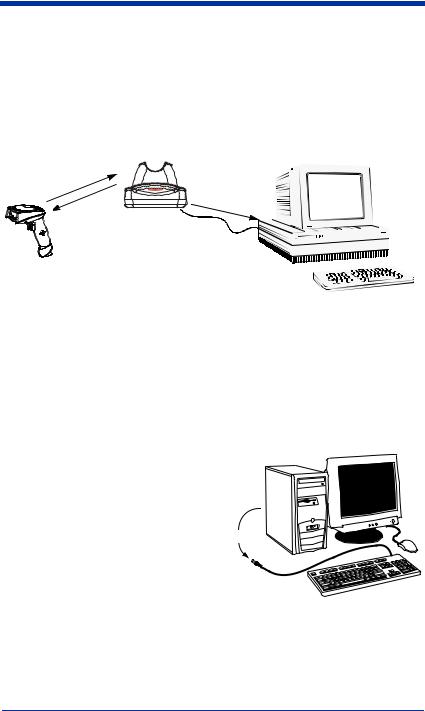
Connecting the Base When Powered by Host (Keyboard Wedge)
A base can be connected between the keyboard and PC as a “keyboard wedge,” plugged into the serial port, or connected to a portable data terminal in wand emulation or non decoded output mode. The following is an example of a keyboard wedge connection:
1.Turn off power to the terminal/computer.
2.Disconnect the keyboard cable from the back of the terminal/ computer.
Disconnect
1 - 12 |
IMAGETEAM™ 2020/5620 System Manual |
3.Connect the appropriate
interface cable |
|
|
to the base and |
|
3 |
to the terminal/ |
|
|
computer and |
|
|
keyboard. |
|
|
4. Turn the |
|
|
terminal/ |
1 |
2 |
computer power |
|
|
|
|
back on.
5.Program the base for the
keyboard wedge interface. See "Keyboard Wedge Connection" on page 1- 14.)
6.Verify the base operation by scanning a bar code from the Sample Symbols in the back of this manual.
Note: Without using the 9-volt external, power supply, the base only uses enough power from the host to operate the interface. The scanner’s battery is not charged when in this mode. Using the 9-volt, external power supply allows the scanner’s battery to be charged, and no power is drawn from the host.
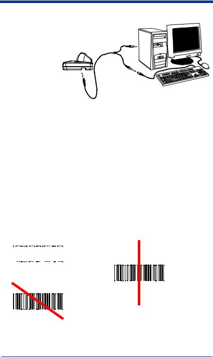
Reading Techniques
The scanner has a view finder that projects a bright red aiming beam that corresponds to its horizontal field of view. The aiming line should be centered horizontally over the bar code; it will not read if the aiming line is in any other direction.
|
|
|
Good Read |
Bad Read |
||||
|
|
|
|
|
|
|
|
|
|
|
|
|
|
|
|
|
|
|
|
|
|
|
|
|
|
|
|
|
|
|
|
|
|
|
|
Bad Read
IMAGETEAM™ 2020/5620 System Manual |
1 - 13 |

The best focus point for reading most code densities is about 5 inches (12.7 cm) from the unit. To read single or multiple symbols (on a page or on an object), hold the imager at an appropriate distance from the target, pull the trigger, and center the aiming line on the symbol.
Resetting the Standard Product Defaults
If you aren’t sure what programming options are in your scanner, or you’ve changed some options and want the factory settings restored, scan the
Standard Product Default Settings bar code below.
The Menu Commands starting on page 10-5 lists the factory default settings for each of the commands (indicated by an asterisk (*) on the programming pages).
Note: Scanning this bar code also causes both the scanner and the base to perform a reset and become unlinked. Refer to "Linking Scanner to Base" on page 1-6 for additional information.
Standard Product Default Settings
Plug and Play
Plug and Play bar codes provide instant scanner set up for commonly used interfaces.
Note: After you scan one of the codes, power cycle the host terminal to have the interface in effect.
Keyboard Wedge Connection
If you want your scanner programmed for an IBM PC AT and compatibles keyboard wedge interface with a USA keyboard, scan the bar code below.
1 - 14 |
IMAGETEAM™ 2020/5620 System Manual |
Loading...