


 Loading...
R7284B,P,U,G
Electronic Oil Primary,
EnviraCOM™ Enabled
|
INSTALLATION INSTRUCTIONS |
APPLICATION |
configure device parameters, retrieve diagnostic |
|
The advanced interface has a two-line display used to |
The R7284B,P,U,G Electronic Oil Primary is a line |
information, and display system status. |
|
|
voltage, safety rated, interrupted and intermittent ignition |
The basic interface has a single LED used to display |
oil primary control for residential oil fired burners used in |
error codes and system status. |
boilers, forced air furnaces and water heaters. The |
In general, the “i” button cycles through the display |
R7284B,P,U,G used with a cad cell flame sensor |
|
operates an oil burner, spark igniter, and optional oil |
options and acts as an “enter” key (in setup modes). |
valve. The control works with a low voltage and optional |
|
high voltage thermostat. The primary controls fuel oil, |
Thermostat(s) |
senses flame, controls ignition spark (either interrupted |
|
or intermittent) and notifies through the EnviraCOM™ |
The oil primaries are compatible with both standard |
bus a remote alarm circuit when in lockout. |
thermostats and EnviraCOM™ communicating |
The R7284 Series of Oil Primary Controls can be used |
thermostats. |
|
|
with both hydronic and forced air systems. When used |
Limited Recycle |
with hydronic systems, line voltage switching Aquastat® |
|
Controllers normally provide for the starting and stopping |
This feature limits the number of recycle trials (for each |
of the combustion sequences. With forced air systems, |
call for heat) to a maximum of three trials. If the flame is |
both mechanical and electronic low voltage thermostats |
lost three times and does not successfully satisfy a call |
control the starting and stopping of the combustion |
for heat, the R7284 locks out. |
process. |
|
Some hydronic and forced air systems require a delayed valve-on and burner motor-off delay. The R7284 operates an oil valve that prevents the flow of oil when the burner motor is running prior to combustion (delayed valve-on) and when the burner motor is running after combustion (burner motor-off delay).
The R7284 models are intended for use only on oil burning appliances which do not require prepurge and post-purge as a safety related function as defined in UL296. The valve-on delay and burner motor-off delay in this control are intended only to help establish draft and reduce oil after-drip related problems.
EnviraCOM™ enabled R7284’s can be used with EnviraLink® remote monitoring systems and hand-held diagnostics. Use only R7284P and U models for networking with other EnviraCOM™ enabled devices.
FEATURES
User Interface
There are two user interfaces: basic and advanced. Both interfaces consist of three buttons: , , and “i.”
Pump Priming Cycle
To facilitate purging air from the oil lines and filters, the R7284 can be placed in a purge routine by pressing and releasing the up arrow button during the Trial For Ignition.
In the advanced interface “PUMP PRIME” is displayed on the display along with the time left on the Trial for Ignition (TFI). Pressing the up arrow button adds a minute to the TFI time for a maximum of 10 additional minutes (press the up arrow button 10 times). Pressing the down arrow button subtracts a minute from the TFI time.
There is no visual indication for the basic interface control and the purge timing is limited to five minutes.
Disable Function
Pressing and holding the “i” button will disable all control functions until 3 seconds after the button is released.
Lockout Modes
The R7284 has three types of lockout modes that are entered when an error is encountered:
69-2467-01
R7284B,P,U,G ELECTRONIC OIL PRIMARY, ENVIRACOM™ ENABLED
• Soft Lockout: Caused by a temporary internal error |
NOTE: |
Some models have adjustable Valve-on Delay, |
||||
such as low voltage. The control recovers |
|
Burner Off Delay, and Lockout timings. |
||||
automatically after the error is no longer detected. |
Electrical Ratings: |
|||||
• Hard Lockout: Caused by a failure internal to the |
||||||
control or by a system fault such as flame out of |
Inputs: |
|
||||
sequence. A Hard Lockout will result in a no heat |
Voltage: 102 to 132 Vac, 120 Vac nominal. |
|||||
condition. To reset from Hard Lockout press and hold |
Current: 0.5A plus burner motor, valve and igniter |
|||||
the “i” button for 2 seconds. |
|
loads. |
||||
• Restricted Lockout: Caused by a number of |
Frequency: 60 Hz. |
|||||
consecutive hard lockouts on the same heat cycle. To |
Outputs: |
|
||||
reset from a Restricted Lockout press and hold the “i” |
Relay Contacts: |
|||||
button for ten seconds. |
|
|
Burner: 120 Vac, 10 full load amperes (FLA), 60 locked |
|||
|
|
|
|
rotor amperes (LRA). |
||
Cad Cell Resistance |
|
Valve: 120 Vac, 1A. |
||||
|
Igniter: 120 Vac, 3 A. |
|||||
Cad cell resistance can be checked without using an ohm |
Low Voltage Shutdown: 80 Vac |
|||||
meter. |
|
|
|
Thermostat Current Available: 100 mA. |
||
Basic Interface: |
|
|
EnviraCOM™ Current Available: 150 mA. |
|||
|
|
NOTE: |
Reduce burner FLA rating by igniter load. For |
|||
Press and release the “i” button. The resulting flashes |
||||||
indicate the resistance. See Table 3. |
|
|
example, if the igniter draws 3A (120 Vac, 360 |
|||
|
|
|
|
|
VA), reduce the burner motor FLA to 7A. |
|
Advanced Interface: |
|
|
Typical Component Wire Color Code: |
|||
The cad cell resistance is shown on the display. |
||||||
|
|
|
|
White: Neutral. |
||
Valve-on Delays/Blower Motor-off |
Black: Line. |
|||||
Orange: Motor. |
||||||
Delays |
|
|
|
Blue or Blue w/White Stripe: Igniter. |
||
|
|
|
Violet: Valve. |
|||
Select models may have fixed or adjustable delays for |
Red: Limit. |
|||||
valve open or blower motor off. The safety circuits will |
|
|
||||
check for flame during these delays and, if a flame is |
NOTE: |
The R7284 is provided with 1/4” quick-connect |
||||
present, will switch the control to lockout. |
|
terminals. |
||||
SPECIFICATIONS |
|
Environmental Ratings: |
||||
|
Operating/Shipping Temperature: -40°F to +150°F |
|||||
|
|
|
|
(-40°C to +66°C). |
||
Models: |
|
|
|
Display text may not be visible below -4°F (-20°C) |
||
|
|
|
Humidity: 0% to 95% relative humidity at 104°F (40°C), |
|||
Table 1 lists the major features for the R7284. |
||||||
noncondensing. |
||||||
|
|
|
|
|||
Timing: |
|
|
|
Accessories: |
||
Valve-on Delay: 0–30 seconds |
|
|||||
|
W8735S3000 Alarm Module |
|||||
Burner Off Delay: 0–8 minutes |
|
|||||
|
|
|
||||
Lockout: 15, 30 or 45 seconds. |
|
Approvals: |
||||
|
Underwriters Laboratories Inc.: Recognized (File MP268). |
|||||
Recycle: 60 seconds (fixed). |
|
|||||
|
Canadian Underwriters Laboratories Inc. |
|||||
Ignition Carryover: 10 seconds (fixed). |
|
|||||
|
|
|
||||
|
|
|
Table 1. R7284 Models. |
|||
|
|
|
|
|
|
|
Model |
Limit |
Valve |
|
|
Notes |
|
R7284B |
No |
Yes |
Valve on delay only |
|
|
|
|
|
|
|
|||
R7284G |
No |
No |
No on/off delays, intermittent ignition (wire igniter together with motor) |
|||
|
|
|
|
|
|
|
R7284P |
Yes |
Yes |
On and off delays |
|
|
|
|
|
|
|
|
|
|
R7284U |
Yes |
Yes |
On and off delays |
|
|
|
|
|
|
|
|
|
|
INSTALLATION
When Installing This Product…
1.Read these instructions carefully. Failure to follow instructions can damage the product or cause a hazardous condition.
2.Check ratings given in these instructions and on the product to make sure the product is suitable for your application.
3.Make sure the installer is a trained, experienced service technician.
4.Use these instructions to check out the product operation after installation.
 WARNING
Electrical Shock Hazard.
Can cause severe injury, death or property damage.
Disconnect power supply before beginning installation to prevent electrical shock or equipment damage. More than one disconnect may be involved.
69-2467—01 |
2 |

R7284B,P,U,G ELECTRONIC OIL PRIMARY, ENVIRACOM™ ENABLED
Location
1.Mount on a 4 in. by 4 in. junction box, directly on the main burner, or inside the appliance cabinet. In replacement applications, mount in the same location as the old control. See Fig. 1. Make sure the operating temperatures are within the ambient temperature range (see Specifications section).
2.Before mounting the control, make line voltage connections as shown in Fig. 2 through 10. Splice lines with solderless connectors. Do not exceed load ratings shown on the device label.
3.If necessary, use the control as a template to mark and drill new mounting holes.
4.Mount the device using No. 6 screws (not included).
WIRING
 WARNING
Electrical Shock Hazard.
Can cause severe injury, death or property damage.
Disconnect power supply before beginning wiring to prevent electrical shock or equipment damage. More than one disconnect may be involved.
1.Make sure wiring complies with all local codes and ordinances.
2.Check to make sure that line voltage wiring is properly connected. Refer to oil primary label and appliance wiring diagram for color codes.
3.After mounting make low voltage connections to the screw terminals (see Fig. 2 through 10).
4.Strip leads 3/8 in. (10 mm) and insert under terminal screw.
5.Connect thermostat leads to T-T (or 1, 2, 3 if EnviraCOM™ is present), if required by installation.
R7284
CHECKOUT
Start System
 WARNING
Fire or Explosion Hazard.
Can cause severe injury, death or property damage.
Make sure the combustion chamber is free of oil and/or oil vapor before starting system.
1.Open hand valve in oil supply line.
2.Make sure system is powered. Check circuit breaker or fuse and close system switch, if provided.
3.Set thermostat to call for heat.
4.Make sure burner lights and operates until call for heat ends. Note cad cell resistance while running.
5.Verify that burner turns off when thermostat call for heat is satisfied.
DISPLAY |
UP BUTTON |
THERMOSTAT |
DOWN |
TERMINALS |
|
|
BUTTON |
ENVIRACOM |
i BUTTON |
|
|
TERMINALS |
|
|
ENVIRACOM |
|
DIAGNOSTIC |
|
PLUG |
DISPLAY |
UP BUTTON |
|
|
THERMOSTAT |
DOWN |
TERMINALS |
|
|
BUTTON |
ENVIRACOM |
i BUTTON |
|
|
TERMINALS |
|
|
ENVIRACOM |
|
DIAGNOSTIC |
|
PLUG |
|
M32146 |
Fig. 2. R7284 terminals, connectors, LED, reset button and DIP switch locations.
CAD CELL CONNECTION
BURNER
M32085
Fig. 1. Mounting R7284 on junction box.
LINE VOLTAGE CONNECTIONS
M32178
Fig. 3. R7284 wiring connections.
3 |
69-2467—01 |
R7284B,P,U,G ELECTRONIC OIL PRIMARY, ENVIRACOM™ ENABLED
R7284B, G |
|
|
|
|
R7284P, U |
|
|
|
|
|
… |
|
|
|
|
… |
|
|
|
|
|
|
|
|
|
LIMIT |
|
AQUASTAT |
|
|
L1 |
|
|
|
|
|
|
|
OR OTHER |
|
|
||
|
|
|
|
|
|
|
|
|||
L1 |
|
AQUASTAT |
|
|
L1 |
|
LIMIT |
|
|
|
|
OR OTHER |
|
L1 |
|
|
|
|
|
||
… |
|
LIMIT |
|
|
… |
|
|
|
|
|
|
|
|
|
|
|
|
|
M32179 |
||
Fig. 4. R7284 Limit wiring for line voltage thermostat, Aquastat, or other Limit.
R7284A, G |
|
|
R7284B, P, U |
|
|
|
… |
VALVE |
L2 |
… |
VALVE |
L2 |
|
VALVE |
||||||
|
BURNER |
BURNER |
BURNER |
BURNER |
MOTOR |
MOTOR |
MOTOR |
MOTOR |
|
… |
… |
|
M32180
Fig. 5. R7284 wiring for optional oil valve.
R7284G
…
BURNER MOTOR
…
|
|
|
|
|
|
R7284B, P, U |
|
|
|
|
|
|
… |
|
|
BURNER |
|
|
L2 |
BURNER |
|
|
MOTOR |
|
|
|
MOTOR |
|
|
|
|
|
|
IGNITER |
|
|
IGNITER |
|
|
|
|
|
|
|
|
|
||
|
|
|
|
|
|
… |
|
|
|
|
|
|
INTERMITTENT
IGNITION
BURNER |
L2 |
|
MOTOR |
||
|
IGNITER
INTERRUPTED IGNITION INTERMITTENT IGNITION
M32181
|
Fig. 6. R7284 igniter wiring. |
|
|||
|
CIRCULATION |
C1 |
AQUASTAT® |
L1 |
|
|
PUMP |
|
C2 |
CONTROLLER |
L2 |
R |
|
|
B2 |
||
|
|
|
1 |
||
|
|
|
|
T |
|
W |
|
|
|
B1 |
|
|
|
|
T |
|
|
THERMOSTAT |
R7284 |
|
L8148A,C |
|
|
|
|
|
|||
T |
LIMIT |
|
|
|
|
|
|
|
|
||
5 JUMPER |
T |
L1 |
|
|
|
|
3 |
L2 |
|
|
|
|
|
|
|
|
|
4 |
2 |
|
|
|
|
ENVIRACOM™ |
1 |
|
|
|
|
TERMINAL |
|
|
|
|
|
|
BURNER |
2 |
|
BURNER |
|
|
MOTOR |
|
|
MOTOR |
|
|
IGNITER |
2 |
|
IGNITER |
|
|
|
|
|
||
|
VALVE |
2 |
|
VALVE |
|
|
|
|
|
||
|
|
|
|
|
3 |
|
CAD |
|
CAD |
|
|
|
CELL |
|
CELL |
|
|
|
|
|
JUNCTION |
|
|
|
|
|
BOX |
|
|
LEGEND: |
SCREW TERMINAL |
1/4 IN. QUICK CONNECT TERMINAL |
|
SOLDERLESS WIRE CONNECTOR |
|
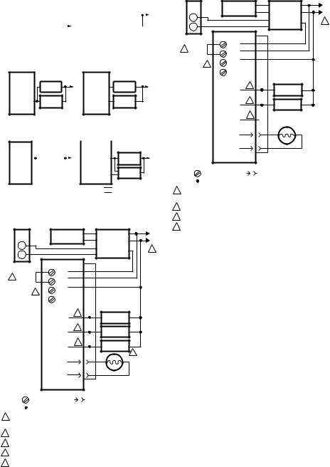
1POWER SUPPLY. PROVIDE DISCONNECT MEANS AND OVERLOAD PROTECTION AS REQUIRED.
2REFER TO DEVICE LABEL FOR WIRE COLOR CODE.
3VALVE IS OPTIONAL ON SPECIFIC MODELS.
4ENVIRACOM™ TERMINAL 3 IS ALSO THE FIRST THERMOSTAT TERMINAL.
5THE JUMPER MAY BE OMITTED IF THE R7284 IS CONFIGURED TO IGNORE
THE TT TERMINALS. |
M32182 |
Fig. 7. Wiring R7284P,U without EnviraCOM™, for typical oil-fired boiler.
|
CIRCULATION |
C1 |
AQUASTAT® |
L1 |
|
|
PUMP |
|
C2 |
CONTROLLER |
L2 |
R |
|
|
B2 |
||
|
|
|
1 |
||
|
|
|
|
T |
|
W |
|
|
|
B1 |
|
|
|
|
T |
|
|
THERMOSTAT |
R7284 |
|
L8148A,C |
|
|
|
|
|
|||
T |
LIMIT |
|
|
|
|
|
|
|
|
||
4 JUMPER |
T |
L1 |
|
|
|
|
3 |
L2 |
|
|
|
|
|
|
|
|
|
3 |
2 |
|
|
|
|
ENVIRACOM™ |
1 |
|
|
|
|
TERMINAL |
|
|
|
|
|
|
BURNER |
2 |
|
BURNER |
|
|
MOTOR |
|
|
MOTOR |
|
|
IGNITER |
2 |
|
IGNITER |
|
|
|
|
|
||
|
VALVE |
2 |
|
|
|
|
|
|
|
|
|
|
CAD |
|
CAD |
|
|
|
CELL |
|
CELL |
|
|
|
|
|
JUNCTION |
|
|
|
|
|
BOX |
|
|
LEGEND: |
SCREW TERMINAL |
1/4 IN. QUICK CONNECT TERMINAL |
|
SOLDERLESS WIRE CONNECTOR |
|
1POWER SUPPLY. PROVIDE DISCONNECT MEANS AND OVERLOAD PROTECTION AS REQUIRED.
2REFER TO DEVICE LABEL FOR WIRE COLOR CODE.
3ENVIRACOM™ TERMINAL 3 IS ALSO THE FIRST THERMOSTAT TERMINAL.
4THE JUMPER MAY BE OMITTED IF THE R7284 IS CONFIGURED TO IGNORE
THE TT TERMINALS. |
M32191 |
Fig. 8. Wiring R7284U without EnviraCOM™, for typical oil-fired boiler.
69-2467—01 |
4 |
Loading...