


 Loading...
Honeywell PVL4022AS, PVL4024NS, PVL6438NS, PVL0000AS, PUL6438S User Manual
...
Spyder® Lon
Programmable, VAV/Unitary Controllers
INSTALLATION INSTRUCTIONS
|
|
|
|
PRODUCT DESCRIPTION |
|
||||
|
|
|
|
The PUL1012S, PUL4024S, PUL6438S, PVL0000AS, |
|||||
|
|
|
|
PVL4022AS, PVL4024NS, PVL6436AS, and PVL6438NS |
|||||
|
|
|
|
controllers are part of the Excel 10 product line family. The |
|||||
|
|
|
|
eight controllers are Free Topology Transceiver (FTT) |
|||||
|
|
|
|
LONMARK→-compliant devices designed to control HVAC |
|||||
|
|
|
|
equipment. These controllers provide many options and |
|||||
|
|
|
|
advanced system features that allow state-of-the-art |
|||||
|
|
|
|
commercial building control. Each controller is programmable |
|||||
|
|
|
|
and configurable through software. |
|
||||
|
|
|
|
These controllers are for use in VAV (Variable Air Volume) and |
|||||
|
|
|
|
Unitary HVAC control applications. Each controller contains a |
|||||
|
|
|
|
host micro controller to run the main HVAC application and a |
|||||
|
|
|
|
second micro controller for LONWORKS® network |
|
||||
|
|
|
|
communications. Each controller has flexible, universal inputs |
|||||
|
|
|
|
for external sensors, digital inputs, and a combination of |
|||||
|
|
|
|
analog and digital Triac outputs. The eight models are |
|||||
|
|
|
|
described in Table 1. The photo to the left is the model |
|||||
|
|
|
|
PVL6436AS, which includes the actuator. |
|
||||
|
|
Table 1. Controller configurations. |
|
|
|
|
|||
|
|
|
|
|
|
|
|
|
|
|
|
|
|
|
|
|
Velocity |
|
|
|
|
Universal |
Digital |
Analog |
|
Digital |
Pressure |
|
Series 60 |
Controller |
Programmable |
Inputs |
Inputs |
Outputs |
|
Outputs |
Sensor |
|
Floating |
Model |
Type |
(UI) |
(DI) |
(AO) |
|
(DO) |
(Microbridge) |
|
Actuator |
PUL1012S |
Unitary |
1a |
0 |
1 |
|
2 |
NO |
|
NO |
PUL4024S |
Unitary |
4a |
0 |
2 |
|
4 |
NO |
|
NO |
PUL6438S |
Unitary |
6 |
4 |
3 |
|
8 |
NO |
|
NO |
|
|
|
|
|
|
|
|
|
|
PVL0000AS |
VAV |
0 |
0 |
0 |
|
0 |
YES |
|
YES |
|
|
|
|
|
|
|
|
|
|
PVL4022AS |
VAV |
4a |
0 |
2 |
|
2 |
YES |
|
YES |
PVL4024NS |
VAV |
4a |
0 |
2 |
|
4 |
YES |
|
NO |
PVL6436AS |
VAV |
6 |
4 |
3 |
|
6 |
YES |
|
YES |
|
|
|
|
|
|
|
|
|
|
PVL6438NS |
VAV |
6 |
4 |
3 |
|
8 |
YES |
|
NO |
|
|
|
|
|
|
|
|
|
|
a One Universal Input (UI-1*) is user selectable as a fast digital pulse meter.
Each controller communicates via the 78 kbps Echelon® LONWORKS® Network, using the FTT-10A LONWORKS® interface, and is LONMARK® compliant.
Controllers are field-mountable to either a panel or a DIN rail.
62-0287—03
SPYDER® LON PROGRAMMABLE, VAV/UNITARY CONTROLLERS
SPECIFICATIONS
General Specifications
Rated Voltage: 20–30 Vac; 50/60 Hz
Power Consumption:
100 VA for controller and all connected loads (including the actuator on models PVL0000AS, PVL4022AS, and PVL6436AS)
Controller Only Load: 20 VA maximum; models PUL1012S, PUL4024S, PUL6438S, PVL4024NS, and PVL6438NS.
Controller and Actuator Load: 21 VA maximum; models PVL0000AS, PVL4022AS, and PVL6436AS
External Sensors Power Output: 20 Vdc ±10% @ 75 mA maximum
VAV Operating & Storage Temperature Ambient Rating (models PVL0000AS, PVL4022AS, PVL4024NS, PVL6436AS, and PVL6438NS):
Minimum 32 F (0 C); Maximum 122 F (50 C)
Unitary Operating & Storage Temperature Ambient Rating (models PUL1012S, PUL4024S, and PUL6438S):
Minimum -40 F (-40 C); Maximum 150 F (65.5 C) Relative Humidity: 5% to 95% non-condensing
LED: Provides status for normal operation, controller download process, alarms, manual mode, and error conditions
BEFORE INSTALLATION
The controller is available in eight models (see Table 1).
Review the power, input, and output specifications on page 2 before installing the controller.
—Hardware driven by Triac outputs must have a minimum current draw, when energized, of 25 mA and a maximum current draw of 500 mA.
—Hardware driven by the analog current outputs must have a maximum resistance of 550 Ohms, resulting in a maximum voltage of 11 volts when driven at 20 mA.
If resistance exceeds 550 Ohms, voltages up to 18 Vdc are possible at the analog output terminal.
 WARNING
Electrical Shock Hazard.
Can cause severe injury, death or property damage.
Disconnect power supply before beginning wiring or making wiring connections to prevent electrical shock or equipment damage.
INSTALLATION
The controller must be mounted in a position that allows clearance for wiring, servicing, removal, connection of the LonWorks® Bus Jack, and access to the Neuron® Service Pin.
The controller may be mounted in any orientation.
IMPORTANT
Avoid mounting in areas where acid fumes or other deteriorating vapors can attack the metal parts of the controller, or in areas where escaping gas or other explosive vapors are present. See Fig. 4–Fig. 7 on page 4 for mounting dimensions.
For PVL0000AS, PVL4022AS, and PVL6436AS models, the actuator is mounted first and then the controller is mounted. For the other models, go to “Mount Controller” on page 4 to begin the installation.
Mount Actuator onto Damper Shaft (PVL0000AS, PVL4022AS, and PVL6436AS)
PVL0000AS, PVL4022AS, and PVL6436AS controllers include the direct-coupled actuator with Declutch mechanism, which is shipped hard-wired to the controller.
The actuator mounts directly onto the VAV box damper shaft and has up to 44 lb-in. (5 Nm) torque, 90-degree stroke, and 90 second timing at 60 Hz. The actuator is suitable for mounting onto a 3/8 to 1/2 in. (10 to 13 mm) square or round VAV box damper shaft. The minimum VAV box damper shaft length is 1-9/16 in. (40 mm).
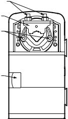
The two mechanical end-limit set screws control the amount of rotation from 12° to 95°. These set screws must be securely fastened in place. To ensure tight closing of the damper, the shaft adapter has a total rotation stroke of 95° (see Fig. 1).
NOTE: The actuator is shipped with the mechanical end-limit set screws set to 95 degrees of rotation. Adjust the two set screws closer together to reduce the rotation travel. Each “hash mark” indicator on the bracket represents approximately 6.5° of rotation per side.
NOTE: The Declutch button, when pressed, allows you to rotate the universal shaft adapter (see Fig. 1).
IMPORTANT
Determine the damper rotation and opening angle prior to installation. See Fig. 2 and Fig. 3 on page 3 for examples.
UNIVERSAL SHAFT
CLAMPING BOLTS (2)
UNIVERSAL |
SHAFT ADAPTER |
MECHANICAL |
END LIMIT SET |
SCREWS (2) |
DECLUTCH |
BUTTON |
M23568 |
Fig. 1. Series 60 Floating Actuator.
IMPORTANT
Mount actuator flush with damper housing or add a spacer between the actuator mounting surface and damper box housing.
62-0287—03 |
2 |

SPYDER® LON PROGRAMMABLE, VAV/UNITARY CONTROLLERS
DAMPER
DAMPER SHAFT |
|
ROTATES |
|
CLOCKWISE |
|
TO OPEN |
M23569 |
Fig. 2. Damper with 90 degree CW rotation to open.
Before Mounting Actuator onto Damper Shaft (PVL0000AS, PVL4022AS, and PVL6436AS)
Tools required:
—Phillips #2 screwdriver - end-limit set screw adjustment
—8 mm wrench - centering clamp
Before mounting the actuator onto the VAV box damper shaft, determine the following:
1.Determine the damper shaft diameter. It must be between 3/8 in. to 1/2 in. (10 to 13 mm).
2.Determine the length of the damper shaft. If the length of the VAV box damper shaft is less than 1-9/16 in. (40 mm), the actuator cannot be used.
3.Determine the direction the damper shaft rotates to open the damper (CW or CCW) (see Fig. 3). Typically, there is an etched line on the end of the damper shaft that indicates the position of the damper. In Fig. 2, the indicator shows the damper open in a CW direction.
4.Determine the damper full opening angle (45, 60, or 90 degrees). In Fig. 2, the damper is open to its full open position of 90 degrees.
TYPE A DAMPER
AIR
FLOW
CW TO OPEN, CCW TO CLOSE
TYPE B DAMPER
AIR
FLOW
M2067B |
CCW TO OPEN, CW TO CLOSE |
Fig. 3. Determining the rotation direction (CW or CCW) for damper opening.
Mounting Actuator onto Damper Shaft (PVL0000AS, PVL4022AS, and PVL6436AS )
The unit is shipped with the actuator set to rotate open in the clockwise (CW) direction to a full 95 degrees. The extra 5 degrees ensures a full opening range for a 90 degree damper. The installation procedure varies depending on the damper opening direction and angle:
1.If the damper rotates clockwise (CW) to open, and the angle of the damper open-to-closed is 90 degrees:
a.Manually open the damper fully (rotate clockwise).
b.Using the Declutch button, rotate the universal shaft adapter fully clockwise.
c.Mount the actuator to the VAV damper box and shaft.
d.Tighten the two bolts on the centering clamp
(8 mm wrench; 70.8–88.5 lb-in. [8–10 Nm] torque). When the actuator closes, the damper rotates CCW 90 degrees to fully close.
2.If the damper rotates clockwise (CW) to open, and the angle of the damper open-to-closed is 45 or 60 degrees:
a.Manually open the damper fully (rotate clockwise).
b.The actuator is shipped with the mechanical end-limits set at 95 degrees. Adjust the two mechanical end-limit set screws to provide the desired amount of rotation. Adjust the two set screws closer together to reduce the rotation travel.
c.Tighten the two mechanical end-limit screws (Phillips #2 screwdriver; (26.5–31 lb-in. [3.0–3.5 Nm] torque).
d.Using the Declutch button, rotate the universal shaft adapter fully clockwise.
e.Mount the actuator to the VAV damper box and shaft.
f.Tighten the two bolts on the centering clamp
(8 mm wrench; 70.8–88.5 lb-in. [8–10 Nm] torque).
g.When the actuator closes, the damper rotates CCW either 45 or 60 degrees to fully close.
3.If the damper rotates counterclockwise (CCW) to open, and the angle of the damper open-to-closed is 90 degrees:
a.Manually open the damper fully (rotate counterclockwise).
b.Using the Declutch button, rotate the universal shaft adapter fully counterclockwise.
c.Mount the actuator to the damper box and shaft.
d.Tighten the two bolts on the centering clamp (8 mm wrench; 70.8–88.5 lb-in. [8–10 Nm] torque). When the actuator closes, the damper rotates CW
90 degrees to fully close.
4.If the damper rotates counterclockwise (CCW) to open, and the angle of the damper open-to-closed is 45 or 60 degrees:
a.Manually open the damper fully (rotate counterclockwise).
b.The actuator is shipped with the mechanical end-limits set at 95 degrees. Adjust the two mechanical end-limit set screws to provide the desired amount of rotation. Adjust the two set screws closer together to reduce the rotation travel.
c.Tighten the two mechanical end-limit screws (Phillips #2 screwdriver; (26.5–31 lb-in. [3.0–3.5 Nm] torque).
d.Using the Declutch button, rotate the universal shaft adapter fully counter-clockwise.
e.Mount the actuator to the VAV damper box and shaft.
f.Tighten the two bolts on the centering clamp
(8 mm wrench; 70.8–88.5 lb-in. [8–10 Nm] torque).
g.When the actuator closes, the damper rotates CW either 45 or 60 degrees to fully close.
3 |
62-0287—03 |
Loading...