


 Loading...
NetAXS-123
Access Control Unit
User’s Guide
If this panel is to be added to an existing loop, then some panels may need to be upgraded.
Please see www.honeywellaccess.com.
April 2010 |
© 2010 Honeywell. All rights reserved. |
800-05168, Revision B |

Copyright© 2010 Honeywell. All rights reserved.
All product and brand names are the service marks, trademarks, registered trademarks, or registered service marks of their respective owners. Printed in the United States of America. Honeywell reserves the right to change any information in this document at any time without prior notice.
NetAXS is a trademark of Honeywell, Inc.
Microsoft and Windows are registered trademarks of Microsoft Corporation. Windows Server is a trademark of Microsoft Corporation.
Ordering Information
Please contact your local Honeywell representative or visit us on the web at www.honeywellaccess.com for information about ordering.
Feedback
Honeywell appreciates your comments about this manual. Please visit us on the web at www.honeywellaccess.com to post your comments.

CONTENTS
Chapter 1 Getting Started
1.1 |
Overview ................................................................................................................... |
2 |
|
1.2 |
Connecting to the Web Server ............................................................................... |
3 |
|
|
1.2.1 |
Setting up the USB Connection........................................................... |
3 |
|
1.2.2 |
Setting up an Ethernet Port.................................................................. |
5 |
1.3 |
Navigating the Landing Page............................................................................... |
11 |
|
1.4 |
Reading the Select Panel....................................................................................... |
13 |
|
Chapter 2 Configuring via the Web Server
2.1 |
Overview ................................................................................................................. |
16 |
|
2.2 |
Configuring the System ........................................................................................ |
18 |
|
|
2.2.1 |
Managing Configuration Data........................................................... |
18 |
|
2.2.2 Host/Loop Communications Tab ...................................................... |
18 |
|
|
2.2.3 |
General Tab ....................................................................................... |
21 |
|
2.2.4 |
Firmware Details Tab ........................................................................ |
25 |
|
2.2.5 Network Tab...................................................................................... |
26 |
|
|
2.2.6 |
Site Codes Tab................................................................................... |
27 |
2.3 |
Configuring Time Management .......................................................................... |
29 |
|
|
2.3.1 Current Time Tab .............................................................................. |
29 |
|
|
2.3.2 Time Zones Tab................................................................................. |
31 |
|
|
2.3.3 |
Holidays Tab ..................................................................................... |
34 |
2.4 |
Configuring the Doors........................................................................................... |
36 |
|
|
2.4.1 Reader A Tab..................................................................................... |
36 |
|
|
2.4.2 Reader B Tab..................................................................................... |
46 |
|
|
2.4.3 |
Outputs Tab ....................................................................................... |
48 |
|
2.4.4 |
Inputs Tab.......................................................................................... |
51 |
2.5 |
Configuring Access Levels................................................................................... |
54 |
|
2.6 |
Maintaining Cards.................................................................................................. |
56 |
|
|
2.6.1 Adding New Cards ............................................................................ |
56 |
|
|
2.6.2 |
Displaying and Modifying Cards ...................................................... |
58 |
|
2.6.3 |
Deleting Cards ................................................................................... |
60 |
|
2.6.4 |
Displaying Reports ............................................................................ |
61 |
2.7 |
Configuring Other I/O........................................................................................... |
63 |
|
|
2.7.1 |
Inputs Tab.......................................................................................... |
63 |
|
2.7.2 |
Outputs Tab ....................................................................................... |
66 |
NetAXS-123 Access Control Unit User’s Guide, Document 800-05168, Revision B |
iii |

2.8 |
Configuring Interlocks .......................................................................................... |
68 |
2.9 |
Configuring Users.................................................................................................. |
70 |
Chapter 3 Using WIN-PAK with NetAXS-123 |
|
|
3.1 |
Overview ................................................................................................................. |
74 |
3.2 |
Configuration Guidelines...................................................................................... |
74 |
|
3.2.1 NetAXS-123 Panel Default Settings ................................................. |
74 |
3.3 |
Supported Configurations..................................................................................... |
77 |
3.4 |
Setting up WIN-PAK ............................................................................................ |
80 |
|
3.4.1 Summary of WIN-PAK I/O Settings for NetAXS-123..................... |
80 |
|
3.4.2 General Setup .................................................................................... |
81 |
3.5 |
WIN-PAK Screen Shots for Door 1.................................................................... |
81 |
3.6 |
WIN-PAK Screen Shots for Door 2.................................................................... |
86 |
3.7 |
WIN-PAK Screen Shots for Door 3.................................................................... |
91 |
3.8 |
Standalone Commands.......................................................................................... |
96 |
|
3.8.1 T (Time) Command........................................................................... |
96 |
|
3.8.2 D (Date) Command ........................................................................... |
97 |
|
3.8.3 L (Time Zone) Command.................................................................. |
98 |
|
3.8.4 C (Card Add) Command ................................................................... |
99 |
|
3.8.5 C (Card Delete) Command.............................................................. |
100 |
|
3.8.6 W (Input) Command........................................................................ |
100 |
|
3.8.7 P (Interlock) Command ................................................................... |
100 |
|
3.8.8 H (Holiday) Command .................................................................... |
101 |
Chapter 4 Monitoring NetAXS-123 Status |
|
|
4.1 |
Overview .............................................................................................................. |
104 |
4.2 |
Monitoring Alarms ............................................................................................. |
105 |
4.3 |
Monitoring Events .............................................................................................. |
109 |
4.4 |
Monitoring Inputs ............................................................................................... |
112 |
4.5 |
Monitoring Outputs ............................................................................................ |
115 |
4.6 |
Monitoring System Status ................................................................................. |
117 |
Chapter 5 File Management |
|
|
5.1 |
Backing up and Restoring the NetAXS-123................................................... |
120 |
5.2 |
Generating Reports ............................................................................................. |
125 |
Appendix A Upgrading NetAXS-123 |
|
|
|
Firmware |
|
A.1 Planning the Upgrade ........................................................................................ |
130 |
|
A.2 Mixed Revision Loops ...................................................................................... |
131 |
|
A.3 Uploading Data from the Panel ....................................................................... |
131 |
|
A.4 Downloading Data to the Panel ....................................................................... |
132 |
|
|
A.4.1 Downloading Data Immediately..................................................... |
132 |
|
A.4.2 Downloading Data Later ................................................................ |
133 |
iv www.honeywell.com

|
A.4.3 Cancelling a Download .................................................................. |
138 |
|
A.5 |
Upgrades to Gateway vs. Multi-drop Panels ................................................. |
140 |
|
A.6 |
Upgrade Notes.................................................................................................... |
142 |
|
|
A.6.1 |
Microsoft Internet Explorer 7 Security Certificate Failure ............ |
142 |
|
A.6.2 |
Firefox 3 Security Certificate Failure............................................. |
148 |
A.7 |
Clearing the Cache............................................................................................. |
151 |
|
|
A.7.1 |
Using Internet Explorer Versions IE7 and IE8............................... |
151 |
|
A.7.2 |
Using Internet Explorer 6 (IE6)...................................................... |
151 |
|
A.7.3 |
Using Firefox 2 or Firefox 3........................................................... |
151 |
Appendix B NetAXS-123 DIP Switch
Settings
NetAXS-123 Access Control Unit User’s Guide, Document 800-05168, Revision B |
v |

vi www.honeywell.com

FIGURES
Figure 1-1: NetAXS-123 Web Server Hub Connection . . . . . . . . . . . . . . . . . . . . . |
5 |
|
Figure 1-2: NetAXS-123 Web Server Direct Connection . . . . . . . . . . . . . . . . . . . . |
6 |
|
Figure 1-3: |
Landing Page . . . . . . . . . . . . . . . . . . . . . . . . . . . . . . . . . . . . . . . . . . . |
10 |
Figure 2-1: |
Communications > Host/Loop > Host/Loop Communications Tab . |
19 |
Figure 2-2: System Tools > General Configuration > General Tab . . . . . . . . . . . |
21 |
|
Figure 2-3: System Tools > Firmware Details Tab . . . . . . . . . . . . . . . . . . . . . . . . |
25 |
|
Figure 2-4: System Tools > General Configuration > Network Tab . . . . . . . . . . |
26 |
|
Figure 2-5: System Tools > General Configuration > Site Codes Tab . . . . . . . . . |
27 |
|
Figure 2-6: Time > Current Time > Current Time Tab . . . . . . . . . . . . . . . . . . . . . |
29 |
|
Figure 2-7: Time > Time Zones > Time Zones Tab . . . . . . . . . . . . . . . . . . . . . . . |
31 |
|
Figure 2-8: Time > Holidays > Holidays Tab . . . . . . . . . . . . . . . . . . . . . . . . . . . . |
34 |
|
Figure 2-9: Configuration > Doors: > 1 > Reader A Tab . . . . . . . . . . . . . . . . . . . |
36 |
|
Figure 2-10: |
Configuration > Doors: > 1 > Reader A Tab > Card Formats . . . . . |
41 |
Figure 2-11: Card Format Editing Screen . . . . . . . . . . . . . . . . . . . . . . . . . . . . . . . |
43 |
|
Figure 2-12: Configuration > Doors: > 1 > Reader B Tab . . . . . . . . . . . . . . . . . . |
46 |
|
Figure 2-13: Reader B Activation In-Progress Message . . . . . . . . . . . . . . . . . . . . |
46 |
|
Figure 2-14: Reader B Fully Activated . . . . . . . . . . . . . . . . . . . . . . . . . . . . . . . . . |
47 |
|
Figure 2-15: Configuration > Doors: > 1 > Outputs > Lock Dialog Box . . . . . . . |
48 |
|
Figure 2-16: Configuration > Doors: > 1 > Outputs Tab > |
|
|
|
Reader LED Dialog Box . . . . . . . . . . . . . . . . . . . . . . . . . . . . . . . . . . |
49 |
Figure 2-17: Configuration > Doors: > 1 > Inputs Tab > Status . . . . . . . . . . . . . . |
51 |
|
Figure 2-18: Input Status Mode - Normally Open - Unsupervised Mode . . . . . . . |
52 |
|
Figure 2-19: Input Status Mode - Normally Closed - Supervised Mode . . . . . . . |
52 |
|
Figure 2-20: Input Status Mode - Normally Open - Supervised Mode . . . . . . . . . |
52 |
|
Figure 2-21: Access Levels > Add/Modify/Delete . . . . . . . . . . . . . . . . . . . . . . . . |
55 |
|
Figure 2-22: |
Cards > Add . . . . . . . . . . . . . . . . . . . . . . . . . . . . . . . . . . . . . . . . . . . |
57 |
Figure 2-23: Cards > Display/Modify . . . . . . . . . . . . . . . . . . . . . . . . . . . . . . . . . . |
59 |
|
Figure 2-24: Cards > Delete . . . . . . . . . . . . . . . . . . . . . . . . . . . . . . . . . . . . . . . . . |
60 |
|
Figure 2-25: Reporting > Card Reports . . . . . . . . . . . . . . . . . . . . . . . . . . . . . . . . . |
61 |
|
Figure 2-26: Configuration > Other I/O > Inputs Tab . . . . . . . . . . . . . . . . . . . . . . |
64 |
|
Figure 2-27: Configuration > Other I/O > Outputs Tab . . . . . . . . . . . . . . . . . . . . |
66 |
|
Figure 2-28: Configuration > Interlocks . . . . . . . . . . . . . . . . . . . . . . . . . . . . . . . . |
68 |
|
Figure 2-29: Users & Accounts > Add/Modify/Delete . . . . . . . . . . . . . . . . . . . . . |
71 |
|
Figure 3-1: Reader Setup for Door 1 . . . . . . . . . . . . . . . . . . . . . . . . . . . . . . . . . . . |
81 |
|
Figure 3-2: Egress Setup for Door 1 . . . . . . . . . . . . . . . . . . . . . . . . . . . . . . . . . . . |
82 |
|
Figure 3-3: Status Setup for Door 1 . . . . . . . . . . . . . . . . . . . . . . . . . . . . . . . . . . . |
83 |
|
Figure 3-4: Lock Setup for Door 1 . . . . . . . . . . . . . . . . . . . . . . . . . . . . . . . . . . . . |
84 |
|
Figure 3-5: Reader LED Setup for Door 1 . . . . . . . . . . . . . . . . . . . . . . . . . . . . . . |
85 |
|
NetAXS-123 Access Control Unit User’s Guide, Document 800-05168, Revision B |
vii |
|

Figure 3-6: Reader Setup for Door 2 . . . . . . . . . . . . . . . . . . . . . . . . . . . . . . . . . |
. . 86 |
Figure 3-7: Egress Setup for Door 2 . . . . . . . . . . . . . . . . . . . . . . . . . . . . . . . . . |
. . 87 |
Figure 3-8: Status Setup for Door 2 . . . . . . . . . . . . . . . . . . . . . . . . . . . . . . . . . . |
. 88 |
Figure 3-9: Lock Setup for Door 2 . . . . . . . . . . . . . . . . . . . . . . . . . . . . . . . . . . . |
. 89 |
Figure 3-10: Reader LED Setup for Door 2 . . . . . . . . . . . . . . . . . . . . . . . . . . . . |
. 90 |
Figure 3-11: Reader Setup for Door 3 . . . . . . . . . . . . . . . . . . . . . . . . . . . . . . . . . |
. 91 |
Figure 3-12: Egress Setup for Door 3 . . . . . . . . . . . . . . . . . . . . . . . . . . . . . . . . . |
. 92 |
Figure 3-13: Status Setup for Door 3 . . . . . . . . . . . . . . . . . . . . . . . . . . . . . . . . . |
. 93 |
Figure 3-14: Lock Setup for Door 3 . . . . . . . . . . . . . . . . . . . . . . . . . . . . . . . . . . |
. 94 |
Figure 3-15: Reader LED Setup for Door 3 . . . . . . . . . . . . . . . . . . . . . . . . . . . . |
. 95 |
Figure 4-1: Monitoring > Alarms > Unacknowledged Tab . . . . . . . . . . . . . . . . |
105 |
Figure 4-2: Monitoring > Alarms > Acknowledged Tab . . . . . . . . . . . . . . . . . . |
106 |
Figure 4-3: Monitoring > Events > Panel Tab . . . . . . . . . . . . . . . . . . . . . . . . . . |
109 |
Figure 4-4: Monitoring > Events > Web Tab . . . . . . . . . . . . . . . . . . . . . . . . . . . |
111 |
Figure 4-5: Monitoring > Inputs . . . . . . . . . . . . . . . . . . . . . . . . . . . . . . . . . . . . . |
112 |
Figure 4-6: Toggle Shunt State Dialog Box . . . . . . . . . . . . . . . . . . . . . . . . . . . . |
113 |
Figure 4-7: Shunted Input Status . . . . . . . . . . . . . . . . . . . . . . . . . . . . . . . . . . . . . |
113 |
Figure 4-8: Time Zone Restore Dialog Box . . . . . . . . . . . . . . . . . . . . . . . . . . . . |
114 |
Figure 4-9: Monitoring > Outputs > Doors/Aux/Other Tab . . . . . . . . . . . . . . . . |
115 |
Figure 4-10: Status > System . . . . . . . . . . . . . . . . . . . . . . . . . . . . . . . . . . . . . . . |
117 |
Figure 5-1: System Tools > File Upload/Download File Management Screen |
. 120 |
Figure 5-2: File Management Manual Time Setting . . . . . . . . . . . . . . . . . . . . . . |
122 |
Figure 5-3: File Management Automatic Time Setting . . . . . . . . . . . . . . . . . . . |
123 |
Figure 5-4: Reporting > Event Reports > By Last Name Tab . . . . . . . . . . . . . . . |
125 |
Figure 5-5: Event Reports By Card Number Example . . . . . . . . . . . . . . . . . . . . |
127 |
Figure A-1: File Management Screen . . . . . . . . . . . . . . . . . . . . . . . . . . . . . . . . . |
131 |
Figure A-2: Immediate Download Confirmation . . . . . . . . . . . . . . . . . . . . . . . . |
132 |
Figure A-3: Deferred Manual Download Confirmation . . . . . . . . . . . . . . . . . . . |
134 |
Figure A-4: Firmware Upgrade Ready for Activation . . . . . . . . . . . . . . . . . . . . |
135 |
Figure A-5: Download Progress Complete . . . . . . . . . . . . . . . . . . . . . . . . . . . . . |
136 |
Figure A-6: Firmware Upgrade Pending . . . . . . . . . . . . . . . . . . . . . . . . . . . . . . . |
137 |
Figure A-7: Deferred Automatic Download Configuration . . . . . . . . . . . . . . . . |
138 |
Figure A-8: Automatic Download Configuration Acknowledgment . . . . . . . . . |
139 |
Figure A-9: Security Certificate Failure Screen . . . . . . . . . . . . . . . . . . . . . . . . . |
142 |
Figure A-10: Security Certificate Failure Correction Login . . . . . . . . . . . . . . . . |
143 |
Figure A-11: Untrusted Certificate Message . . . . . . . . . . . . . . . . . . . . . . . . . . . . |
143 |
Figure A-12: Certificate Information Screen . . . . . . . . . . . . . . . . . . . . . . . . . . . |
144 |
Figure A-13: Certificate Import Wizard Welcome Screen . . . . . . . . . . . . . . . . . |
145 |
Figure A-14: Certificate Store Screen . . . . . . . . . . . . . . . . . . . . . . . . . . . . . . . . . |
145 |
Figure A-15: Certificate Import Wizard Completion Screen . . . . . . . . . . . . . . . |
146 |
Figure A-16: Security Warning Screen . . . . . . . . . . . . . . . . . . . . . . . . . . . . . . . . |
146 |
Figure A-17: Successful Import Message . . . . . . . . . . . . . . . . . . . . . . . . . . . . . . |
147 |
Figure A-18: Security Certificate Login . . . . . . . . . . . . . . . . . . . . . . . . . . . . . . . |
147 |
Figure A-19: Secure Connection Failed Message . . . . . . . . . . . . . . . . . . . . . . . . |
148 |
Figure A-20: Add Security Exception Screen . . . . . . . . . . . . . . . . . . . . . . . . . . . |
149 |
Figure A-21: Unknown Identity Message Screen . . . . . . . . . . . . . . . . . . . . . . . . |
150 |
viii www.honeywell.com

TABLES
Table 1-1: Landing Page Icons .................................................................................................. |
11 |
Table 1-2: Reading the Select Panel .......................................................................................... |
13 |
Table 2-1: Configuration Task Sequence .................................................................................. |
16 |
Table 2-2: Communications > Host/Loop > Host Loop Communications Tab Fields ............. |
20 |
Table 2-3: System Tools > General Configuration > General Tab Fields ................................ |
22 |
Table 2-4: Time > Current Time > Current Time Tab Fields ................................................... |
30 |
Table 2-5: Configuration > Doors > 1 > Reader A Tab Fields ................................................. |
37 |
Table 2-6: Configuration > Doors: > 1 > Reader A Tab > |
|
Card Format Fields .................................................................................................... |
42 |
Table 2-7: Configuration > Doors: > 1 > Reader A > Card Format Fields ............................... |
43 |
Table 2-8: Configuration > Doors: > 1 > Outputs Tab > Reader LED Dialog Box Fields ....... |
50 |
Table 2-9: Configuration > Doors: > 1 > Inputs Tab Fields ..................................................... |
53 |
Table 2-10: Cards > Add Cards Fields ...................................................................................... |
57 |
Table 2-11: Reporting > Card Reports Fields ........................................................................... |
62 |
Table 2-12: Configuration > Other I/O > Inputs Tab Fields ..................................................... |
65 |
Table 2-13: Configuration > Other I/O > Outputs Tab Fields .................................................. |
67 |
Table 2-14: Configuration > Interlocks Fields .......................................................................... |
69 |
Table 2-15: User Functions ....................................................................................................... |
70 |
Table 3-1: Controller Board I/O Defaults for Door #1 ............................................................. |
74 |
Table 3-2: Factory Default Configuration Settings for Door 2 ................................................. |
75 |
Table 3-3: Factory Default Configuration Settings for Door 3 ................................................. |
76 |
Table 3-4: NetAXS-123/NS4 Interoperability Using a Web Server ......................................... |
77 |
Table 3-5: NetAXS-123/NS4 Interoperability using WIN-PAK .............................................. |
78 |
Table 3-6: NetAXS-123 to WIN-PAK Mapping ...................................................................... |
80 |
Table 3-7: NetAXS-123 Panel Interlock Configuration ............................................................ |
80 |
Table 4-1: Monitoring > Alarms Fields .................................................................................. |
107 |
Table 4-2: Logical (LN) and Physical (PN) Numbers of Common Panel Events .................. |
108 |
Table 4-3: Monitoring > Events > Panel Tab Fields ............................................................... |
110 |
Table 5-1: Status > Report Fields ............................................................................................ |
126 |
Table B-1: NetAXS-123 SW1 DIP Switch Settings ............................................................... |
153 |
Table B-2: NetAXS-123 SW2 DIP Switch Settings ............................................................... |
155 |
NetAXS-123 Access Control Unit User’s Guide, Document 800-05168, Revision B |
ix |

NetAXS-123 Access Control Unit User’s Guide, Document 800-05168, Revision B |
x |
Getting Started |
1 |
|
In this chapter... |
|
Overview |
2 |
Connecting to the Web Server |
3 |
Navigating the Landing Page |
11 |
Reading the Select Panel |
13 |
NetAXS-123 Access Control Unit User’s Guide, Document 800-05168, Revision B |
1 |

Getting Started
Overview
1.1 Overview
The NetAXS-123 is a modular 1-, 2- or 3-Door access control system. A NetAXS-123 access control site is configured with a host system and access control units that exceed existing N-1000-III/IV, Pro Series specifications and approvals. These units also communicate with each other and with a variety of input and output devices. Each access control unit, or panel, has three reader ports. Each port can support two readers. For supported configurations, see Supported Configurations, page 77.
You can communicate with the NetAXS-123 access control unit either through a host software system or by connecting to the web server through an Ethernet connection. This chapter describes how to connect to the web server.
2 www.honeywell.com
Getting Started
Connecting to the Web Server
1.2 Connecting to the Web Server
This section describes three configurations for connecting a computer to the
NetAXS-123 web server:
•USB
•Ethernet through a web server hub connection
•Ethernet through a web server direct connection
Note: The panel that you are connecting to the computer is the Gateway panel. DIP switch 6 on a Gateway panel must be set to ON for a successful connection.
1.2.1 Setting up the USB Connection
Warning: Do NOT connect the USB cable to the panel until AFTER the drivers are installed.
Follow these steps to set up the NetAXS-123 USB connection.
1.Insert the NetAXS-123 Product CD into your Windows-based computer. The NetAXS-123 product menu opens in the web browser.
Note: If the product menu does not open automatically in your browser, right click on the Start button and select Explore. In the folder tree, find and click the CD drive that is reading the NetAXS-123 Product CD.
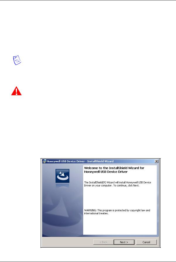
2.Click Install USB Drivers on the product menu to start the USB driver installation wizard.
NetAXS-123 Access Control Unit User’s Guide, Document 800-05168, Revision B |
3 |
Getting Started
Connecting to the Web Server
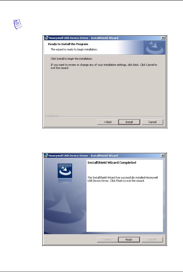
3. Click Next to display the Ready to Install the Program screen.
Note: If confirmation dialog boxes pop up before or during the installation, click the appropriate boxes to allow or approve the installation.
4.Click Install to initiate the installation.
5.When the installation is complete, the closing screen appears:
6. Click Finish.
4 www.honeywell.com
Getting Started
Connecting to the Web Server
7.Connect the computer to the NetAXS-123 controller with a USB-A to Micro USB-B cable.
8.Turn on the power to the NetAXS-123 controller.
For login information, go to https://192.168.2.150.
1.2.2 Setting up an Ethernet Port
There are two options for connecting the panel to a PC via a web server:
•Using a hub connection
•Using a direct connection
Perform the following steps:
1.Connect your computer's Ethernet port to the panel's Ethernet Port using one of the two following methods:
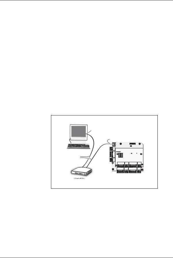
a.For an Ethernet Hub connection, connect both the computer’s Ethernet port and the panel's Ethernet port to an Ethernet hub with standard Ethernet patch cables.
Figure 1-1: NetAXS-123 Web Server Hub Connection
Terminal
Ethernet Port
Ethernet Port
Ethernet
Cable
LEDs |
|
LED |
LED |
NetAXS-123 Panel (Controller Board with
1-Door I/O Board mounted on top)
NetAXS-123 Access Control Unit User’s Guide, Document 800-05168, Revision B |
5 |
Getting Started
Connecting to the Web Server
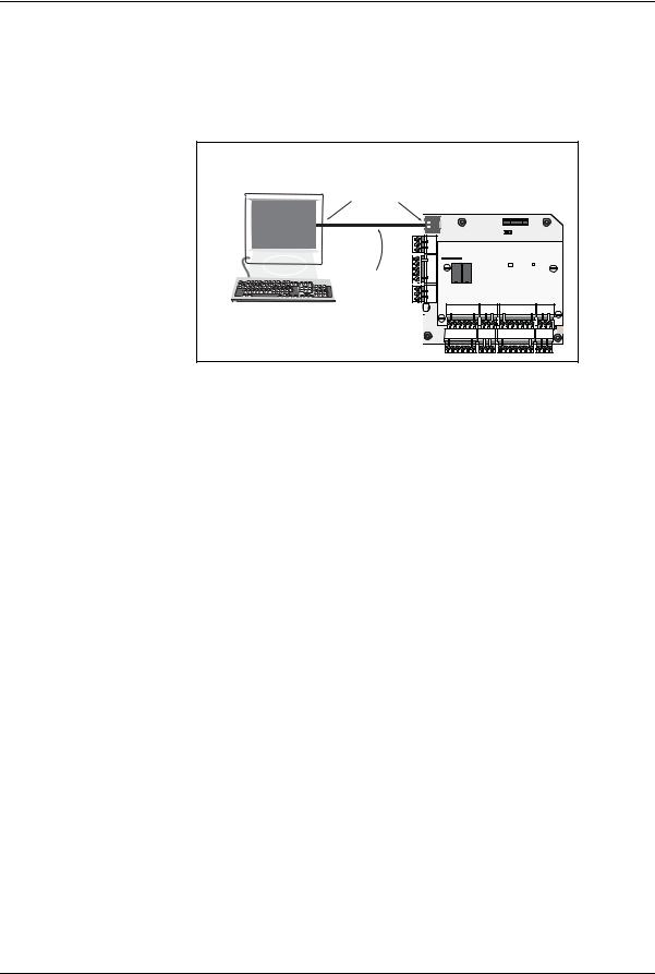
b.For a web server direct connection, connect the computer’s Ethernet port directly to the panel’s Ethernet port with either a crossover or an Ethernet cable.
Figure 1-2: NetAXS-123 Web Server Direct Connection
Terminal |
NetAXS-123 Panel |
|
Ethernet Port |
(Controller Board with |
|
|
1-Door I/O Board mounted on top) |
|
|
10 |
1 |
|
|
NO |
Ethernet
Cable
LEDs |
LED |
LED |
2.Configure the computer’s network connection:
a.Select Start > Settings > Control Panel.
b.Click Network and Dial-up Connections.
6 www.honeywell.com
Getting Started
Connecting to the Web Server
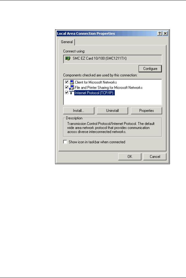
c.Identify your local Ethernet connection (commonly labeled Local Area Connection), and right-click the icon to display the Local Area Connection Properties screen.
d.Highlight the Internet Protocol (TCP/IP) connection.
e.Click Properties to display your system’s current Internet Protocol properties.
Important: Keep a record of your computer’s current network configuration as it appears in this screen. You will need to re-instate this configuration later.
f.Select "Use the following IP address."
g.Enter "192.168.1.150" in the IP address field.
NetAXS-123 Access Control Unit User’s Guide, Document 800-05168, Revision B |
7 |

Getting Started
Connecting to the Web Server
h. Enter "255.255.255.0" in the Subnet mask field.
i.Click OK to accept the entries.
3.Open your browser (Internet Explorer shown below), and enter https://192.168.1.150 as the target address.
Caution: When connecting to the web using a browser, you must use https:// for a secure connection. The standard http:// that is the default in most browsers will not work.
8 www.honeywell.com
Getting Started
Connecting to the Web Server
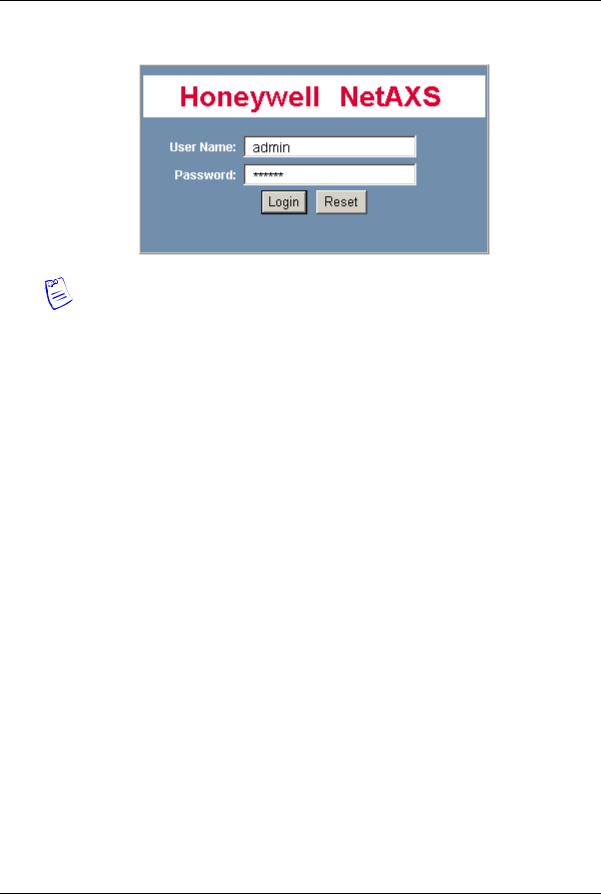
4. Press the Enter key to display the Honeywell NetAXS-123 login screen.
Note: If you are using Microsoft Internet Explorer 7 and you receive a certificate error message, follow these steps to clear it:
a.Enter the IP address of the panel into the URL box.
b.Click Continue to the website (not recommended) to display the login screen.
c.Click Certificate Error at the top-right of the IP address. The “Untrusted Certificate” screen appears.
d.Click the View Certificates bar. The “Certificate Information” screen appears.
e.Click Install Certificate. The “Certificate Import Wizard” screen appears.
f.Click Next and follow the prompts; leave all settings at their default values. A Security Warning asks if you want to install the certificate.
g.Click Yes. A Certificate Import Wizard message states “The import was successful.”
h.Click OK. The Certification Information message appears again.
i.Click OK.
j.Close the web browser and re-open it.
k.Enter the IP address again into the URL box. The login screen appears without the certificate error.
5.Enter “admin” in the User Name field, and enter “admin” in the Password field. Both the user name and password are case-sensitive.
Note: It is recommended that you change your default user name (admin) and password (admin) to a new user name and password at this time. To do this, proceed to the instructions in Configuring Users, page 70.
NetAXS-123 Access Control Unit User’s Guide, Document 800-05168, Revision B |
9 |
Getting Started
Connecting to the Web Server
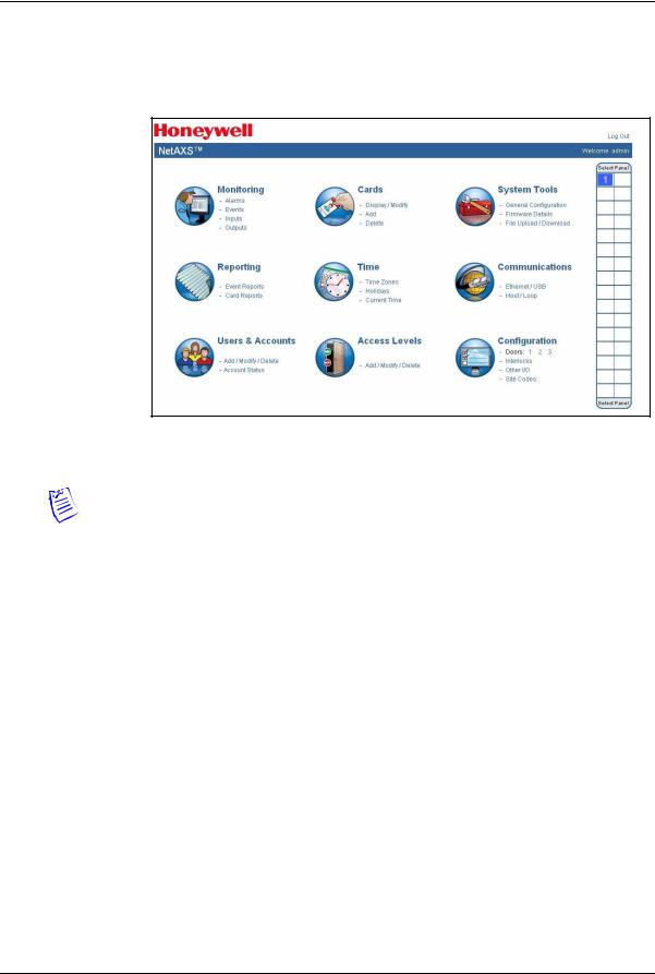
6.Click Login to display the NetAXS-123 Main Window, sometimes also referred to as the “Landing Page”.
Figure 1-3: Landing Page
Note: The Select Panel column on the right edge of the Main Window displays all panels available to the computer. This list displays the number of the gateway panel that you are connected to over Ethernet and any downstream panels connected via RS-485 to the Gateway panel.
10 www.honeywell.com
Getting Started
Navigating the Landing Page
1.3 Navigating the Landing Page
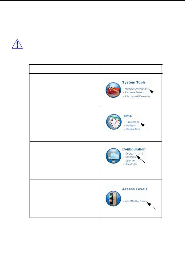
The opening screen displays icons representing the functions available.
Table 1-1: Landing Page Icons
Icon |
Description |
For more information, see.. |
|
|
|
|
|
|
View status monitoring |
Monitoring System Status, page 117 |
|
|
|
|
|
|
Generate event reports and card |
Maintaining Cards, page 56 and |
|
|
reports |
Generating Reports, page 125 |
|
|
|
|
|
|
Create, modify, and delete users, |
Configuring Users, page 70 |
|
|
and checks account status |
|
|
|
|
|
|
|
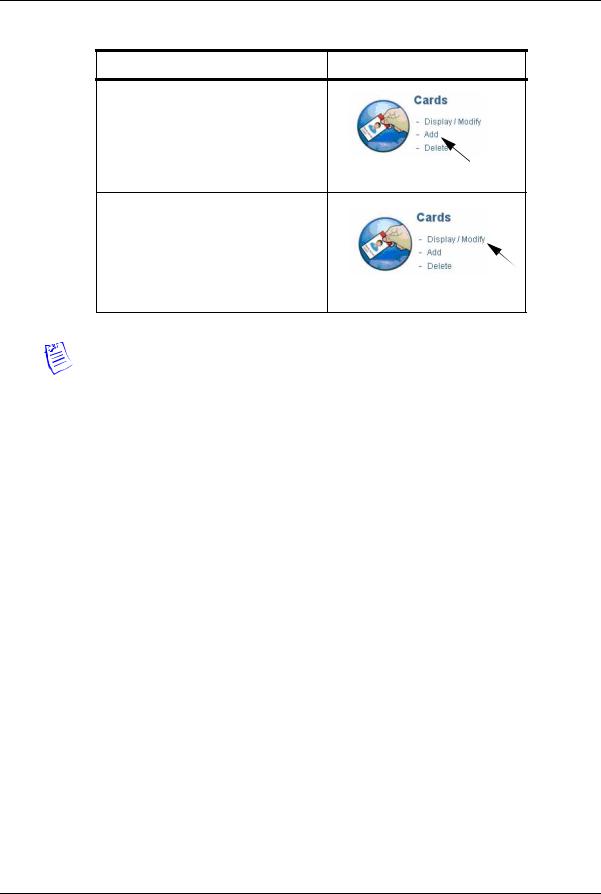
Manage cardholder cards |
Maintaining Cards, page 56 |
|
|
|
|
|
|
Configure time management |
Time Zones Tab, page 31 |
|
|
|
|
|
|
Manages access levels |
Configuring Access Levels, page 54 |
|
|
|
|
|
|
|
|
|
NetAXS-123 Access Control Unit User’s Guide, Document 800-05168, Revision B |
11 |
Getting Started
Navigating the Landing Page
Table 1-1: Landing Page Icons (continued)
Icon |
Description |
For more information, see.. |
|
|
|
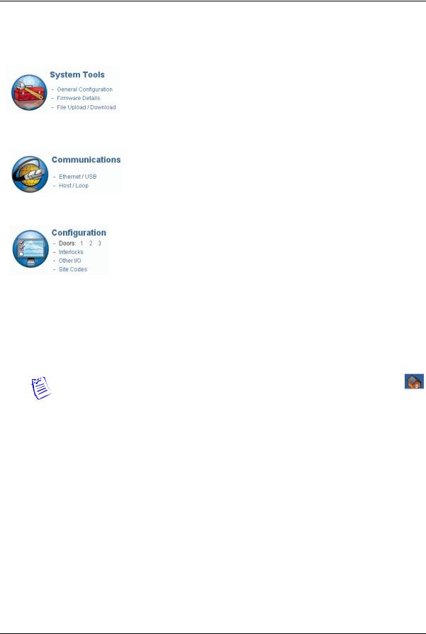
|
Provides file management |
Generating Reports, page 125 |
|
functionality |
|
|
|
|
|
Configure connectivity |
Configuring the System, page 18 |
|
|
|
|
Provides system configuration |
Configuring the System, page 18 |
|
functionalitya |
|
|
|
|
a.The number of doors shown next to this icon reflects the actual number of doors the panel is configured for. The example in the table displays a Controller Board with a 2-door input/output board (I/O board), thus resulting in a total of three doors. The Controller lists only the door, no numbers. A Controller with a 1-door I/O board will report Doors: 1 2.
Note: To return to the home page at any time, simply click the Home Page icon.
12 www.honeywell.com
Getting Started
Reading the Select Panel
1.4 Reading the Select Panel
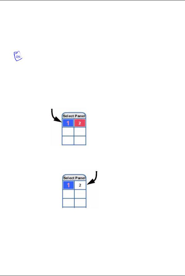
The Select Panel is located at the right margin of the NetAXS-123 web server main screen. The presence of a number in one of the Select Panel cells indicates that its associated panel is online. For example, if you see a number 1 in a cell, this indicates that panel 1 is online. The combinations of size and color of the number and the color of the cell background indicate the panel’s status, as shown in the following table.
Note: Holding the cursor over a cell also displays a popup message, which indicates whether the panel in that cell is online or selected.
The Select Panel refreshes automatically when the panel’s status changes.
Table 1-2: Reading the Select Panel
Cell Display |
Status |
|
|
Large red number on a blue background, such as |
Panel 1 is selected, and it has |
“1” in the example below: |
unacknowledged alarms. |
|
|
Small black number on white background, such as |
Panel 2 is not selected and it has |
“2” in the example below: |
no unacknowledged alarms. |
|
|
NetAXS-123 Access Control Unit User’s Guide, Document 800-05168, Revision B |
13 |
Getting Started
Reading the Select Panel
Table 1-2: Reading the Select Panel (continued)
Cell Display |
Status |
|
|
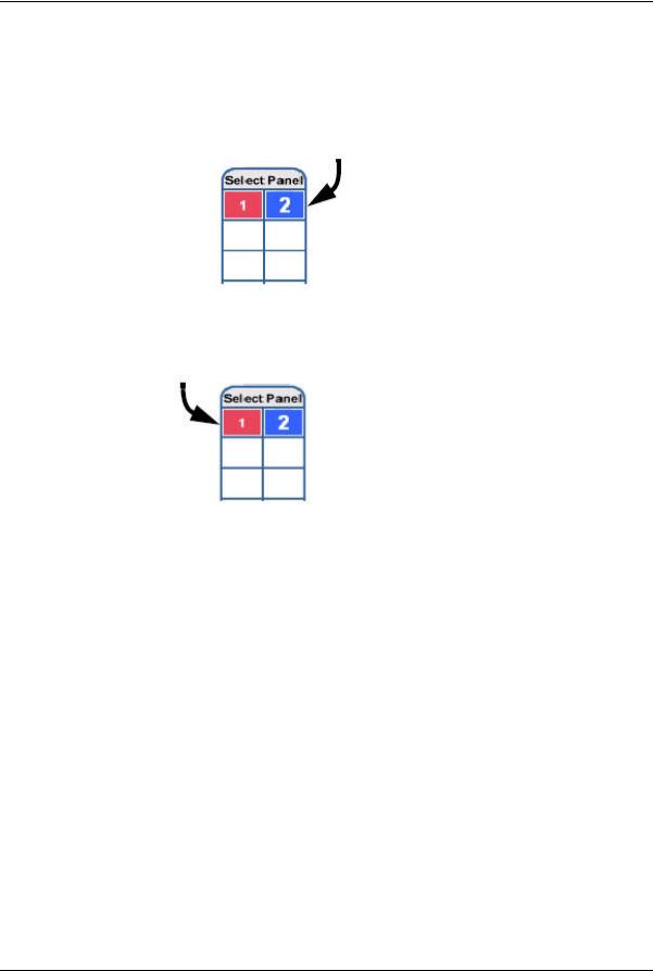
Large white number on blue background, such as |
Panel 2 is selected, and it has no |
“2” in the example below: |
unacknowledged alarms. |
|
|
Small white number on a red background, such as |
Panel 1 is not selected, but it does |
“1” in the example below: |
have unacknowledged alarms. |
|
|
14 www.honeywell.com

Configuring via the Web Server 2
In this chapter... |
|
Overview |
16 |
Configuring the System |
18 |
Configuring Time Management |
29 |
Configuring the Doors |
36 |
Configuring Access Levels |
54 |
Maintaining Cards |
56 |
Configuring Other I/O |
63 |
Configuring Interlocks |
68 |
Configuring Users |
70 |
NetAXS-123 Access Control Unit User’s Guide, Document 800-05168, Revision B |
15 |
Configuring via the Web Server
Overview
2.1 Overview
This chapter explains the NetAXS-123 configuration functions as accessed via the web server. These functions should be performed only by the system administrator or service personnel.
Caution: The sequence of NetAXS-123 configuration tasks is critical. If you do not follow the sequence described in Table 2-1, the system cannot be successfully configured.
Table 2-1: Configuration Task Sequence
To perform this task... |
Click this heading |
1. Configure the panel:
Host/Loop Communications Network
General Site Codes
2.Configure the time zones.
3.Configure the doors:
Readers
Outputs
Inputs
4. Configure the access levels.
16 www.honeywell.com
Configuring via the Web Server
Overview
Table 2-1: Configuration Task Sequence (continued)
To perform this task... |
Click this heading |
5.Create the cards and assign access levels.
6.Modify access levels to cards.
Note: This guide contains many screen captures. These screens have been captured on a Windows XP platform; they may look somewhat different, depending on your platform.
NetAXS-123 Access Control Unit User’s Guide, Document 800-05168, Revision B |
17 |

Configuring via the Web Server
Configuring the System
2.2 Configuring the System
2.2.1 Managing Configuration Data
This section provides an overview of how configuration data is managed on a system of panels interconnected via an RS-485 communications loop.
Some configuration data is common to all panels on the loop. When common data is entered, it is sent to and stored on all panels that are online at the time the data is entered. Common data includes:
•Time Zones
•Cards
•Card Formats
•Site Codes
•Holidays
•Access Level Name and Number (access level details are panel-specific)
•System Configuration (Site Codes)
Other data is panel-specific and unique for each panel. Panel-specific data includes:
•Access Level Time Zone Reader Assignments
•Door/Reader Configuration
•System Configuration (General Tab)
•System Configuration (Firmware Details)
•System Configuration (Network) (IP addresses apply only to gateway panel)
•System Configuration (Host/Loop Communications) (applies only to gateway panel)
•Web Users (applies only to gateway panel)
If common data is modified when a panel is off-line, or if a new panel is attached to a loop after common data has been entered, the panel must be manually re-synchronized to obtain the common data. To resynchronize a new panel, you must upload a copy of the gateway panels common and card database and then download to the out-of-sync panel. See Section 5.1, "Backing up and Restoring the NetAXS-123" on page 120 for additional details.
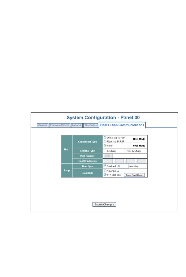
2.2.2 Host/Loop Communications Tab
To maintain your NetAXS-123 system configuration or to monitor its status, you must connect to the panel using one of two modes:
•Host mode (monitor only) – a host software system, such as WIN-PAK™, connects to the panel (through the gateway panel, which has an on-board PCI communications adapter). It enables you to monitor the status of the system.
•Web mode (configure and monitor) – the web server connects to the panel and enables you to configure the panel and monitor system status.
18 www.honeywell.com
Configuring via the Web Server
Configuring the System
The Host/Loop Communications tab enables you to:
•Select and configure the communication mode you will use to connect to the panel.
•Configure the following host settings:
–Connection Type (host or web server)
–Comms Type
–Port Number
–Host IP Address
•Configure the loop:
–Time Sync (Enable—how often in minutes the gateway will broadcast its time to downstream panels)
–Baud Rate (for communication among downstream panels)
Click Communications > Host/Loop > Host/Loop Communications Tab to display the Host/Loop Communications Tab.
Figure 2-1: Communications > Host/Loop > Host/Loop Communications Tab
NetAXS-123 Access Control Unit User’s Guide, Document 800-05168, Revision B |
19 |

Configuring via the Web Server
Configuring the System
Steps: Use the descriptions in Table 2-2 to configure the settings:
Table 2-2: Communications > Host/Loop > Host Loop Communications Tab Fields
Host/Loop |
Setting |
Description |
|
|
|
|
Connection type |
Specifies the type of physical connection |
|
|
between the host and the Gateway panel. |
|
|
If you are connecting from a host software |
|
|
system such as WIN-PAK, select one of the |
|
|
following three connection options: |
|
|
Direct via TCP/IP – Host initiates connection |
|
|
to panel. |
|
|
Reverse TCP/IP – Panel connects directly to |
|
|
the host system using the TCP/IP protocol. |
|
|
You must enter the host IP address in the Host |
|
|
IP Address field. Panel initiates connection to |
|
|
host. Panel currently does not support |
|
|
encryption. |
|
|
None – Select this if you are using web mode. |
|
|
|
|
Comms Type |
Specifies the type of communications. |
Host |
|
Ack/NAK – Provides a response (either an |
|
|
acknowledgment or a non-acknowledgment) |
|
|
in a transmission between the host and |
|
|
panel(s). This is the recommended |
|
|
communications type. |
|
|
Non Ack/NAK – Does not provide a response |
|
|
(either an acknowledgment or a |
|
|
non-acknowledgment) in a transmission |
|
|
between the host and panel(s). Normally used |
|
|
in troubleshooting only. |
|
|
|
|
Port Number |
Specifies the port number for the Ethernet port |
|
|
(default is 3001). (Default for Reverse TCP/IP |
|
|
is 5001.) |
|
|
|
|
Host IP Address |
Enter the host system (or WIN-PAK server) IP |
|
|
address here if you selected Reverse TCP/IP |
|
|
in the Connection Type field on this screen. |
|
|
|
20 www.honeywell.com
Loading...