


ML7420A
M
L7420
M
T
L7425
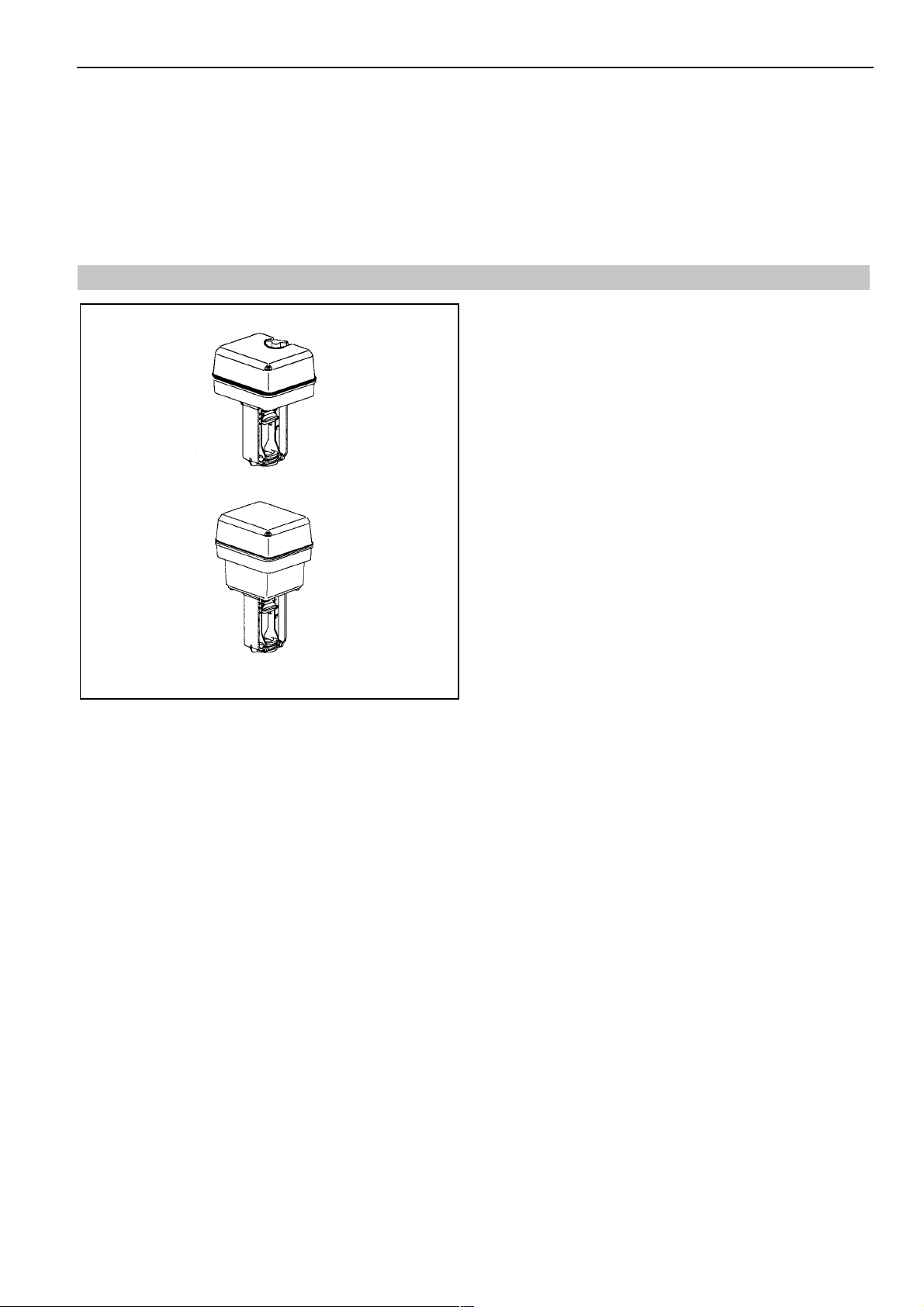
ML7420A/ML7425A,B
Electric Linear Valve Actuator
SPECIFICATION DATA
FEATURES
Easy and quick installation
•
No separate linkage required
•
No adjustments
•
Low power consumption
•
Force limiting end switches
•
Spring return models
•
Manual operator
•
0 to 10Vdc or 2 to 10Vdc signal input
•
Position feedback signal
•
Synchronous motor
•
Direct / reverse action
•
Stroke position on signal failure selectable
•
Corrosion resistant design
•
Maintenance free
•
GENERAL
The ML7420A / ML7425A,B actuators are for modulating
control with controls providing an analog output of
0 to 10Vdc or 2 to 10Vdc. They operate Honeywell’s standard
valves in heating, ventilation and air conditioning (HVAC)
applications. The direction of movement is reversible by
means of an internal selector plug.
SPECIFICATIONS
Temperature Limits
Ambient operating limits -10 to +50°C
Ambient storage limits -40 to +70°C
Medium valve
temperature Max. 150°C
Signals
Signal input voltage y =
R
Signal source output
resistance 1kΩ max.
Position feedback signal x = 2 to 10Vdc
Load 1mA max.
Safety
Protection class II in acc. with EN60730-1
Protection standard IP54 in acc. with EN60529
Flame retardant
housing V0 in acc. with UL94
(with metal cable gland)
0 to 10Vdc or 2 to10Vdc
= 100k
i
@ 5 to 95%rh
@ 5 to 95%rh
Ω
his product meets the re quirements of
EN0B-0624GE02 R0399
CE
ML7420A/ML7425A,B
Wiring
Wiring terminals 1.5mm
Cable entry PG13.5. Two additional knock
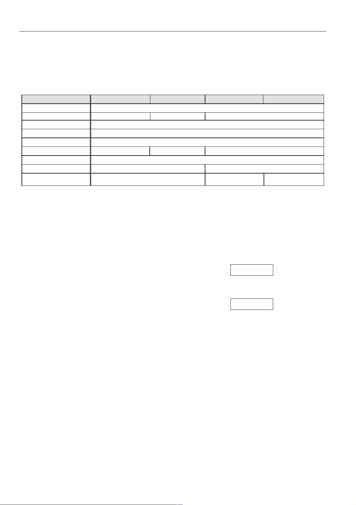
Model Number ML7420A3006 ML7420A3014 ML7425A3005 ML7425B3004
Supply Voltage 24Vac +/-15% 50/60Hz
Power Consumption
Signal Input 0(2)Vdc Actuator stem retracted. Two way valve:”open”, three way valve port A-AB:”closed” *
Signal Input 10Vdc Actuator stem extended. Two way valve:”closed”, Three way valve port A-AB:”open” *
Stroke 20mm
Run Time @ 50Hz 1min 0.5min 1.8min
Close-off Force ≥ 600N
Spring Return Time
Spring Return Direction
* Factory setting; can be reversed by action selector plug W3
2
outs PG11 and PG13.5 for
auxiliary switch and
potentiometer accessories
5VA 7VA 12VA
OPERATION
Weight
non spring return type 1.3kg
spring return type 2.4kg
Material
Cover ABS-FR
Base glass fibre reinforced plastic
Yoke aluminium diecast
≈12s
Actuator stem extends
at power failure
Actuator stem retracts
at power failure
General
The drive of a synchronous motor is converted into linear
motion of the actuator stem by using a spur gear
transmission. The actuator stem is connected with the valve
stem by a button keyed retainer connection.
An integrated spring package limits the stem force to a
factory adjusted value in either direction.
Installed microswitches switch off the actuator precisely
when the specified stem force is reached.
Manual Operation
Actuators without spring return are equipped with a manual
operator used in case of power failure. Manual operation is
only possible after the power supply is switched off or
disconnected.
To operate push the manual operator knob down and turn
clockwise to move the stem downward and counter-clockwise
to move the stem upward. If the actuator returns to automatic
control, the manual operator knob unlocks automatically.
On actuators with spring return the manual operator is
located under the cover.
Spring Return
The ML7425A,B spring return types provide a defined safety
position of the valve in case of power failure.
The spring return actuators are shipped from the factory with
a shipment stop (to lock the knob) in order to allow
connection of the stem button retainer to the valve stem
without power supply.
Electrical Installation
The actuators are delivered with a pre-installed cable gland
PG13.5 and two additional knock outs for PG11 and PG13.5.
Cable length/diameter for field mounting:
•
Max. 200m/1.5mm
100m/1.5mm
To avoid malfunction it is necessary to connect 24Vac
power and ground (see Fig. 2).
In case of replacement please note that the override
switch has been changed (see Fig. 2).
2
or
2
(ML7420A3014)
NOTE
CAUTION
NOTE
CAUTION
Input Signal Failure
By means of selector plug W1* the actuator can be selected
such, that in case of a signal input failure,(e.g. a broken wire)
the actuator will run to one of the three positions:
0%: actuator stem position for 0(2)Vdc
50%: actuator stem in central position
100%: actuator stem position for 10Vdc
W1 is set by the factory to 50%.
Input Signal Range
The range of the analog input signal Y can be changed by
changing the position of selector plug W2*
EN0B-0624GE02 R0399 2
Action
The direction of action can be changed by repositioning of
selector plug W3*. It is set by the factory such that the stem
extends at increasing signal and retracts at decreasing
signal.
NOTE
CAUTION
*Jumper plugs W1, W2 and W3 are accessible after the
cover has been removed. They are located on the rear
side of the protection sheet of the printed circuit board
(see EN1C-0073 and EN1C-0074).
Output Signal ”POSITION”
An analog output signal 2 to 10Vdc ”POSITION” is available
which represents the actual actuator position. It can be used
for remote indication.
When the actuator stem is extended the output signal is
10Vdc.
Accessories
Auxiliary switches
The actuators can be equipped on site with an auxiliary
switch unit with two switches. Their switching points are
adjustable over the full length of the actuator stroke. The
switches can be used to switch pumps or provide remote
indication of any stroke position.
A cable gland PG13.5 is delivered with the unit.
Part number: 43191680-005
ML7420A/ML7425A,B
Auxiliary potentiometer
Auxiliary potentiometers are available for mounting on site.
They can be used as feedback potentiometer and or to
provide remote indication to the valve position.
A cable gland PG13.5 is delivered with the unit.
Part number: 43191679-011 (10kΩ)
Part number: 43191679-012 (220Ω)
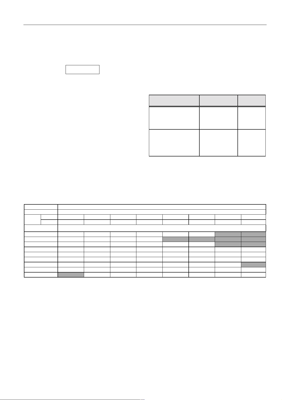
High Temperature Kit
(for applications >150°C medium temperature)
High Temperature Kit,
Order Number
43196000-001
43196000-002
Valve DN
V5011A/V5011K
V5013A/V5013G
V5011R/V5013R
V5328A/V5329A
V5011A
V5013A/V5013G
V5328A/V5329A
V5049A
V5050A
15 - 40
15 - 40
15 - 50
15 - 32
50
50
40 - 80
15 - 65
15 - 80
CLOSE-OFF PRESSURE RATINGS in kPa
Stem Force 600N
Stroke 20mm
Valve mm 15 20 25 32 40 50 65 80
Size inch 1/2 3/4 1 1 1/4 1 1/2 2 2 1/2 3
Valves Close-Off Pressure Ratings
V5011R 1600 1600 1000 700 460 260
V5011K 1600 1600 1300 1000
V5013R 1600 1600 1000 700 460 260
V5328A 1600/1000 1000 1000 600 350 200 120 50
V5329A (PN16) 1000 1000 1000 790 480 260 160 100
V5329C (PN6) 600 600 600 600 480 260 160 100
V5049A 1600/1000 1000 1000 600 350 200 120
V5050A 1000 1000 1000 600 350 200 120 50
V5095A 1600 1600 1600 1600 1600 1600 1600
For specific data of above valves see Specification Data No.:
V5011R EN0B-064
V5011K EN0C-0560
V5013R EN0B-065
V5328A EN0C-0432
V5329A,C EN0C-0434
V5049A EN0C-0433
V5050A EN0C-0435
V5095A EN0C-0490
3 EN0B-0624GE02 R0399
 Loading...