


 Loading...
Galaxy 2 Series
Installation Manual
Honeywell Security
Galaxy 2 Series Installation Manual |
|
Table of Contents |
|
|
|
Contents
SECTION 1: INTRODUCTION .................................................................... |
1 |
Optional Peripherals ............................................................................................. |
1 |
Features .................................................................................................................. |
2 |
RF ........................................................................................................................................... |
2 |
Groups ................................................................................................................................... |
2 |
Dialler ..................................................................................................................................... |
2 |
SMS Text Messaging............................................................................................................ |
2 |
ProxKeypads ........................................................................................................................ |
2 |
Remote Servicing ................................................................................................................. |
2 |
SECTION 2: QUICK GUIDE ........................................................................ |
3 |
How to Boot up ...................................................................................................... |
3 |
Default Codes......................................................................................................... |
3 |
Menu Access Operation/Navigation .................................................................... |
3 |
How to get in and out of Engineer Mode ............................................................ |
3 |
How to Set/Unset.................................................................................................... |
3 |
How to Restore an Alarm ...................................................................................... |
4 |
SECTION 3: SYSTEM ARCHITECTURE .................................................... |
5 |
SECTION 4: SYSTEM WIRING ................................................................... |
6 |
General Information .............................................................................................. |
6 |
Siting ...................................................................................................................................... |
6 |
Ventilation.............................................................................................................................. |
6 |
Cabling .................................................................................................................................. |
6 |
Mains Cable Type ................................................................................................................. |
6 |
Zone and Data Cable Type .................................................................................................. |
7 |
Mains Supply Connection................................................................................................... |
7 |
Equipment Electrical Rating ................................................................................. |
8 |
Batteries ................................................................................................................................ |
8 |
Fuses ..................................................................................................................................... |
8 |
i

Table of Contents |
Galaxy 2 Series Installation Manual |
|
Connecting the Galaxy 2 Series to the PSTN ..................................................... |
9 |
|
Private Branch Exchange (PBX) Approval ........................................................................ |
9 |
|
REN and SEN Numbers...................................................................................................... |
|
10 |
SECTION 5: HARDWARE ......................................................................... |
|
11 |
PCB Layout (2–44+) ............................................................................................. |
|
11 |
PCB Layout (2–20) ............................................................................................... |
|
12 |
Zones ................................................................................................................................... |
|
13 |
Zone Links ................................................................................................................................................. |
|
13 |
Wiring Zones ............................................................................................................................................. |
|
14 |
Wiring Keyswitches ................................................................................................................................... |
|
14 |
Wiring Push-Set Buttons ............................................................................................................................ |
|
14 |
Zone Addresses ................................................................................................................. |
|
15 |
Zone Numbering System .......................................................................................................................... |
|
15 |
Outputs ................................................................................................................................ |
|
16 |
Trigger Header .................................................................................................................... |
|
16 |
Trig 1-8 ....................................................................................................................................................... |
|
16 |
Inputs ......................................................................................................................................................... |
|
17 |
Supply ....................................................................................................................................................... |
|
17 |
Data Buses .......................................................................................................................... |
|
17 |
RS485 Wiring Configurations ..................................................................................................................... |
|
17 |
RS485 Wiring Recommendations ............................................................................................................. |
|
18 |
ECP Bus (2–44+ Only) .............................................................................................................................. |
|
19 |
Built-in Dialler/Modem ........................................................................................................ |
|
19 |
LED’S.................................................................................................................................... |
|
19 |
Audio Header (2–44+ Only) ............................................................................................... |
|
19 |
GSM Interface (2–44+ Only)............................................................................................... |
|
19 |
Panel Mounting (Plastic Box) ............................................................................. |
|
20 |
Installation Kit ..................................................................................................................... |
|
20 |
Removing the Enclosure Lid ............................................................................................ |
|
20 |
Installing the Enclosure Lid .............................................................................................. |
|
20 |
Removing and Replacing the Galaxy 2 Series PCB ...................................................... |
20 |
|
Remove the PCB ...................................................................................................................................... |
|
21 |
Replace the PCB ....................................................................................................................................... |
|
21 |
Mounting the Plastic Enclosure Base ............................................................................. |
21 |
|
Fitting the Tamper Spring ................................................................................................. |
|
21 |
Panel Mounting (Metal Box) ............................................................................... |
|
22 |
Installation Kit ..................................................................................................................... |
|
22 |
Removing and Installing the Enclosure Lid ................................................................... |
22 |
|
Removing and Replacing the Galaxy 2 Series PCB ...................................................... |
23 |
|
Mounting the Metal Enclosure Base................................................................................ |
|
23 |
ii

Galaxy 2 Series Installation Manual |
Table of Contents |
Peripherals - Installation, Wiring & Addressing |
............................................... 24 |
Configuring ......................................................................................................................... |
24 |
General ................................................................................................................................ |
24 |
Mk7 LCD Keypad/Keyprox ................................................................................................ |
25 |
Keypad/Keyprox Installation ..................................................................................................................... |
25 |
Mk7 Keypad/Keyprox Addressing ........................................................................................................... |
26 |
Adding a Mk7 Keypad/Keyprox to the System ........................................................................................ |
26 |
Remote Input Output (RIO) ................................................................................................ |
27 |
Addressing the RIO ................................................................................................................................... |
27 |
Connecting the RIO ................................................................................................................................... |
27 |
Configuring the RIO ................................................................................................................................... |
28 |
Zones ......................................................................................................................................................... |
28 |
Outputs ...................................................................................................................................................... |
28 |
Power Supply Unit .............................................................................................................. |
29 |
Configuration .............................................................................................................................................. |
29 |
Installation Instructions ............................................................................................................................... |
30 |
Battery ........................................................................................................................................................ |
31 |
Battery Test ................................................................................................................................................ |
31 |
Specifications ............................................................................................................................................ |
31 |
EN50131 Compliance ................................................................................................................................ |
31 |
ECP Zone Expander (2–44+ Only) .................................................................................... |
32 |
Zone Expander Outputs ............................................................................................................................ |
32 |
Addressing the ECP Zone Expander ....................................................................................................... |
33 |
5800H RF Receiver (2–44+ Only) ...................................................................................... |
33 |
Installation .................................................................................................................................................. |
33 |
Wiring ......................................................................................................................................................... |
33 |
Addressing ................................................................................................................................................ |
33 |
G2 RF Portal ........................................................................................................................ |
34 |
Mounting the Plastic Base ......................................................................................................................... |
34 |
Attaching the PCB ...................................................................................................................................... |
35 |
Addressing the RF Portal .......................................................................................................................... |
35 |
Connecting the RF Portal .......................................................................................................................... |
36 |
Configuring the RF Portal .......................................................................................................................... |
36 |
Attaching the Plastic Box Lid ..................................................................................................................... |
36 |
Specifications ............................................................................................................................................ |
36 |
EN50131 Compliance ................................................................................................................................ |
36 |
6160 Keypad/Keyprox/RFH (2–44+ Only) ........................................................................ |
37 |
Installation and Wiring ................................................................................................................................ |
37 |
Addressing the 6160 Keypad ................................................................................................................... |
38 |
Addressing the 6160 Keyprox .................................................................................................................. |
38 |
Addressing the 6160 RFH ......................................................................................................................... |
38 |
2-Way Audio (2–44+ Only) ................................................................................................. |
39 |
Operation of 2-Way Audio ......................................................................................................................... |
40 |
GSM Module (2–44+ Only) ................................................................................................. |
41 |
Characteristics ........................................................................................................................................... |
42 |
Compliance ............................................................................................................................................... |
42 |
iii

Table of Contents |
Galaxy 2 Series Installation Manual |
|
SECTION 6: GENERAL OPERATION ...................................................... |
43 |
|
Galaxy 2 Series Users ......................................................................................... |
|
43 |
Users .................................................................................................................................... |
|
43 |
Engineers ............................................................................................................................ |
|
43 |
General Menu Operation..................................................................................... |
|
43 |
Full Setting .......................................................................................................................... |
|
44 |
Part Setting .......................................................................................................................... |
|
44 |
Night Setting ....................................................................................................................... |
|
45 |
Cancelling the Setting ....................................................................................................... |
|
45 |
Unsetting the System ........................................................................................................ |
|
45 |
Cancelling Alarms and Alerts ........................................................................................... |
|
45 |
Alert Indication ................................................................................................................... |
|
45 |
Restoring alarms ................................................................................................................ |
|
46 |
Overriding of Faults and Tampers ................................................................................... |
|
46 |
Setting and Unsetting with Keyfobs ................................................................................ |
|
47 |
Setting and Unsetting with Keytags or Cards ................................................................ |
48 |
|
Text Programming.............................................................................................................. |
|
49 |
Additional Functions ......................................................................................................... |
|
50 |
Code Tampers ........................................................................................................................................... |
|
50 |
Hot Keys .................................................................................................................................................... |
|
50 |
SECTION 7: MENU OPTIONS .................................................................. |
|
51 |
Menu 10 - Setting Options................................................................................................. |
|
51 |
Option 11 - Omit Zones .............................................................................................................................. |
|
51 |
Option 12 - Timed Set ............................................................................................................................... |
|
51 |
Option 13 - Part Set ................................................................................................................................... |
|
51 |
Option 14 - Night Set ................................................................................................................................. |
|
51 |
Option 15 - Chime ...................................................................................................................................... |
|
51 |
Menu 20 - Display Options ................................................................................................ |
|
52 |
Option 21 - Zone Status ............................................................................................................................. |
|
52 |
Option 22 - View Log ................................................................................................................................. |
|
52 |
Option 23 - System Version ...................................................................................................................... |
|
53 |
Option 24 - Print ......................................................................................................................................... |
|
53 |
Menu 30 - Test Options...................................................................................................... |
|
54 |
Option 31 - Walk Test ................................................................................................................................ |
|
54 |
Option 32 - Output Test .............................................................................................................................. |
|
54 |
Menu 40 - Modify Options ................................................................................................. |
|
55 |
Option 41 - Time/Date ................................................................................................................................ |
|
55 |
Option 42 - Users ...................................................................................................................................... |
|
55 |
Adding Keyfobs (ECP) .......................................................................................................................................... |
|
57 |
Adding Keyfobs (RS485) ...................................................................................................................................... |
|
57 |
Removing Keyfobs ............................................................................................................................................... |
|
57 |
Adding Keytags or Cards - Mk7 485 Keyprox only ............................................................................................... |
58 |
|
Adding Keytags or Cards - 6160 Keyprox only |
..................................................................................................... |
58 |
iv

Galaxy 2 Series Installation Manual |
Table of Contents |
Removing Keytags or Cards - Mk7 485 Keyprox only ......................................................................................... |
58 |
Removing Keytags or Cards - ECP 6160 Tags only ............................................................................................ |
58 |
Option 44 - Mobile Nos ............................................................................................................................. |
59 |
Option 47 - Remote Access ...................................................................................................................... |
60 |
Option 48 - Level 3 Access ....................................................................................................................... |
60 |
Menu 50 - Engineer 1 Options .......................................................................................... |
61 |
Option 51 - Parameters ............................................................................................................................. |
61 |
Option 52 - Zones ...................................................................................................................................... |
73 |
Option 53 - Outputs .................................................................................................................................... |
79 |
Option 56 - Comms ................................................................................................................................... |
82 |
Option 57 - System Print ........................................................................................................................... |
94 |
Menu 60 - Engineer 2 Options .......................................................................................... |
95 |
Option 61 - Diagnostics ............................................................................................................................. |
95 |
Option 62 - Full Test ................................................................................................................................... |
96 |
Option 63 - Options ................................................................................................................................... |
97 |
SECTION 8: RF HINTS AND TIPS ............................................................ |
99 |
How to Install RF................................................................................................................. |
99 |
RF Zones ............................................................................................................................. |
99 |
RF Stop Set ......................................................................................................................... |
99 |
RF Diagnostics ................................................................................................................... |
99 |
SECTION 9: FINAL COMMISSIONING ................................................... |
100 |
Final system Test ............................................................................................................. |
100 |
User Information............................................................................................................... |
100 |
SECTION 10: REMOTE SERVICING ...................................................... |
101 |
Telephone Line Set-Up .................................................................................................... |
101 |
Direct Wire Set-Up ............................................................................................................ |
101 |
Remote Programming ..................................................................................................... |
101 |
SECTION 11: FLASH UPGRADE ........................................................... |
102 |
SECTION 12: PRINTER CONNECTION ................................................. |
103 |
SECTION 13: BELL-BOX CONNECTIONS ............................................ |
104 |
SECTION 14: EVENT LOG LIST ............................................................ |
105 |
v

Table of Contents |
Galaxy 2 Series Installation Manual |
|
SECTION 15: SPECIFICATIONS |
............................................................ |
108 |
SECTION 16: COMPLIANCE AND ...................................APPROVALS |
110 |
|
EN50131 Compliance....................................................................................................... |
|
110 |
Public Switched Telephone Network ...............................................(PSTN) Approval |
110 |
|
HONEYWELL SECURITY LIMITED ....................................WARRANTY |
111 |
|
Appendix A: Point ID Comms Triggers ................................................ |
A-1 |
|
vi

Galaxy 2 Series Installation Manual |
Introduction |
|
|
SECTION 1: INTRODUCTION
The Galaxy 2 Series is a 12-zone intruder alarm control panel. There are 2 variants. The 2-44+ is the full function version which is expandable to 44 zones. The 2-20 is an entry level version which is expandable to 20 zones. This manual covers both versions. However, certain features are not available on the 2-20 variant.
The following table gives the general specification for both variants.
|
|
|
|
Feature |
|
Specification |
|
|
Galaxy 2-20 |
|
Galaxy 2-44+ |
Zones |
12 expandable to 20 |
|
12 expandable 44 |
Outputs |
4+8 expandable to 16 |
|
4+8 expandable to 28 |
Databuses |
RS485 Only |
|
RS485 and ECP |
PSU |
1A (0.6A @ Grade 2) |
|
1.4A (1A @ Grade 2) |
Alphanumeric LCD Keypads/ |
4 |
|
4 |
Alphanumeric LCD KeyProx |
|
||
|
|
|
|
|
|
|
|
RIO (8 zones/4 outputs) |
1 |
|
4 |
RF Receiver |
2 |
|
2 |
User Codes (PIN and Card) |
23 |
|
23 |
Groups |
3+1 common group |
|
3+1 common group |
Part Set |
2 Part Sets |
|
2 Part Sets |
Silent Night Set |
Yes |
|
Yes |
Zone Types |
18 |
|
18 |
O/P Types |
23 |
|
23 |
Event Log |
384 |
|
384 |
Multi-Users |
4 |
|
4 |
Printer Module |
Optional |
|
Optional |
PSTN Communicator/Modem |
On-Board |
|
On-Board |
GSM Comunicator/Modem |
- |
|
Plug on Option |
Serial Port |
1 on-board |
|
1 on-board |
2-way Voice |
- |
|
Optional |
Table 1. General Specifications
The Galaxy 2 Series requires at least one external keypad for programming and general operation. There are two main types of keypad available.
Galaxy Mk7 LCD Keypad: This keypad has a 2 x 16 character display and operates on the RS485 data bus. Optionally, a keyprox version is available. This is a standard Mk7 keypad with a proximity card reader built in to the lower right-hand corner. The keyprox is for set/unset only.
6160 Full Text Keypad: This keypad has a 2 x 16 character display and operates on the ECP data bus. Optionally versions are available with built-in prox reader and wireless receiver.
Optional Peripherals
Zone Expander: This gives eight extra hardwire zones and four programmable outputs.Alternatively four extra hardwire zones and no outputs.
1
|
Galaxy 2 Series Installation Manual |
Introduction (cont’d) |
|
|
|
RF Radio Receiver: This allows the control panel to receive signals from wire-free detectors and radio keyfobs. One radio receiver will allow the panel to assign wire-free detectors to any or all of the 44 detection zones. However, two receivers can be used to increase coverage.
Proximity Card Reader: This allows users to set/unset simply by swiping a card or tag in front of the reader. The proximity card readers are built into the housing of the keypads.
RIO/ PSU Control: Up to four RIO’s or PSU’s can be added to the RS485 Bus. Each RIO/ PSU Control expands the system by eight zones and four outputs.
GSM Module: This module provides mobile telecommunications between the panel and theAlarm Receiving Center (ARC).
Features
RF
The system operates with the 5800 receivers on ECP and/or the RF Portal on RS485.Amaximum of two RF receivers can be fitted to the system (two on the ECP bus, two on the RS485 bus or one on each bus), to support up to 44 zones. The RF receivers are in addition to the prox keypads on RS485 but in place of ECP prox keypads.
Groups
Group functionality allows the system to be split into three individual sub-systems that can be set and unset independently.Additionally there is a fourth common group which will set automatically when all the other groups have set. It is unset as soon as any one group has been unset by a user. Zones are assigned users to a single group only. Users are assigned to one or more groups.
Dialler
The system can have two active comms devices configured, chosen from:
•On-board PSTN/Modem
•Plug-on GSM Module
These are used for Dial-up primary and secondary signalling, as well as remote servicing and two-way audio.
SMS Text Messaging
This is a secondary alarm notification to keyholders. Text messages are sent to GSM mobile phones, giving information on panel events.
ProxKeypads
These are standard keypads with an added proximity card reader, combined into one housing. This allows dual function setting/unsetting ability from the one station without the need for a separate card reader. They are primarily intended for use in situations where a PIN card is needed to set and unset the intruder alarm system.
Remote Servicing
The Galaxy 2 series control panel can be remotely and/or locally serviced by a Personal computer (PC). This is accomplished when the Remote Servicing Software is installed on the PC.
2
Galaxy 2 Series Installation Manual |
Quick Guide |
|
|
SECTION 2: QUICK GUIDE
How to Boot up
Wire up the keypads, address them (see Peripherals - Installation, Wiring andAddressing), then apply power to the system. The keypads will configure and show the default banner display.
Galaxy 44 V1.0
09:51 SAT 01 JAN
Default Codes
Default User Code: 1234 Default Engineer code: 112233
Menu Access Operation/Navigation
Only valid codes can access the Galaxy 2 Series menu options. Type the code then press ent to access the menu.
Data entry, on both ECP and RS485 keypads, is via the 0-9 function keys and the *, # on the keypad. The A> and <B keys are curser or scroll keys and are used to scroll through options in menus.
The ent key is used to enter a PIN code and to accept screen information. The esc key is used to cancel or exit from the current operation.
NOTE: Users cannot view or access options for which they are not authorised.
How to get in and out of Engineer Mode
Entry to engineer mode is authorised by a user in menu option 48 = Level 3Access. Following this the engineer will have five minutes in which to enter his code. When the engineer code is entered four things happen:
•All system tampers become isolated.
•All fault signalling is suppressed, and indications are silent.
•The engineer is given access to the full menu.
•The banner message is changed to indicate engineer mode.
To bring the system back out of engineer access mode and reinstate all the tampers from the banner, the engineer enters his code but presses the esc key rather than the ent key.
How to Set/Unset
To Full Set the system, the user types their code then presses the A key.
To Part Set the system, the user types their code, presses the B key then presses the [1] key. To Night Set the system, the user types their code, presses the B key then presses the [2] key. To Unset the system, the user types their code then presses ent.
3
Quick Guide (cont’d) |
Galaxy 2 Series Installation Manual |
How to Restore an Alarm
Alarms, faults and tampers will be restored provided:
1.The cause has cleared
2.An authorised user PIN code or anti-code has been entered.
3.The conditions have been viewed on the keypad display after steps 1 and 2 above.
If a user cannot restore all the conditions, a temporary banner is displayed to indicate that a manager or engineer is required to restore the system. This lasts for 30 seconds before the normal banner is displayed.
4
Galaxy 2 Series Installation Manual |
|
Architecture |
|
|
|
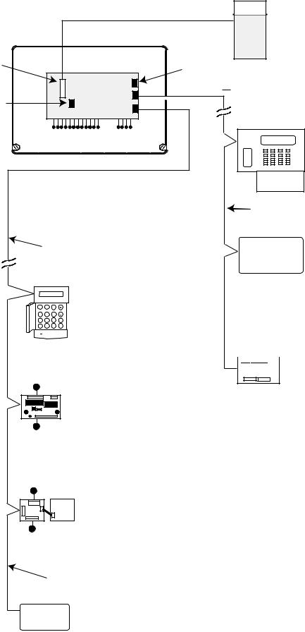
SECTION 3: SYSTEM ARCHITECTURE
|
12-way ribbon cable |
External |
|
|
|
|
|
Communicator |
Trigger |
|
|
Header |
|
Phone line |
|
|
|
|
Galaxy 2-44 |
ECP BUS (2 44+ only) |
Serial Port to PC |
PCB |
|
12 on-board zones |
4 outputs |
6160 keypad (4) |
|
|
(optionally with |
|
|
built-in |
RS485 BUS |
|
receiver/keyprox) |
|
|
Note: maximum of |
|
|
2 receivers/keyproxes |
Note: A maximum of 4 keypads (including keyprox) can be connected to the RS485 line.
Maximum cable length from panel to last module on line is 1km
|
GALAXY 44 V1.0 |
|
Mk7 LCD |
|
|
09:51 |
01/08/04 |
|
|
1 |
2 |
3 |
A Keypad/Keyprox |
|
|
(4) |
|||
4 |
5 |
6 |
B |
|
7 |
8 |
9 |
ent |
|
* |
0 |
# |
esc |
|
4 outputs
RIO (4)
C072
8 zones
OR
4 outputs
Power Unit (4) P025 or
Power RIO (4) P026
Maximum cable length from panel to last module on line is 100m
5800 RF receiver (2)
Standard 4-core cable
 spurred or T wired
 ECP zone expander 8 zone, 4 output (3)
|
|
|
|
|
|
|
MODULE |
TOTAL |
ADDRESSES |
ECP |
RS485 |
PLUG-ON |
|
QTY |
AVAILABLE |
|||||
|
|
|
|
|||
Keypads |
4 |
0,1, 2, 3 |
4 |
4 |
|
|
|
|
|
|
|
|
|
Keyprox |
4 |
0,1, 2, 3 |
2 |
2 |
|
|
|
|
|
|
|
|
|
Expanders* |
4 on RS485 |
2, 3, 4, 5 |
3 |
4 |
|
|
|
or |
|
|
|
|
|
|
3 on ECP |
|
|
|
|
|
RF Receivers |
2 |
4, 5 |
2 |
2 |
|
|
|
|
|
|
|
|
|
PSU Control/RIO |
4 |
2, 3, 4, 5 |
- |
4 |
|
|
|
|
|
|
|
|
|
GSM (2-44+ only) |
1 |
- |
- |
- |
1 |
|
2-way Voice (2-44+ only |
1 |
- |
- |
- |
1 |
|
|
|
|
|
|
|
* Only the first expander can be used on the 2-20
8 zones
Twisted pair screened cable
Belden 8723 equivalent.
Daisy chain configuration only.
RF Portal (2)
Figure 1. Galaxy 2 Series System Configuration
5
|
Galaxy 2 Series Installation Manual |
System Wiring |
|
|
|
SECTION 4: SYSTEM WIRING
General Information
It is essential that this product is installed correctly, in particular with respect to a person’s safety and connection to the mains electricity supply. This product is not suitable for installation, maintenance or connection by the user.Acompetent, qualified engineer, with for example NACOSS approval, must carry out installation and maintenance.
Siting
The control panel enclosure (plastic box or metal box), must be sited indoors in a secure area where it cannot be readily interfered with. There must be adequate ventilation, ample light and easy access for servicing and maintenance. It is not suitable for siting externally or in harsh environments where it could be subject to high humidity, extremes of temperature, chemical atmospheres, high dust levels, or in a position where it may be subject to being dripped on, or splashed by, water or other fluids.
The enclosure base must be securely fixed to a vertical, smooth, solid surface that is a part of the fabric of the building. The position chosen must allow the cabinet lid to be removed and allow unhindered access for installation and maintenance.
Ventilation
While the control panel has been designed so that no part attains an unsafe temperature it is important that adequate ventilation is provided around the cabinet, therefore the cabinet must not be positioned close to heat-radiating equipment or other sources of heat.
Cabling
The panel has high voltage barriers between the a.c. mains supply and the alarm wiring terminals. It is essential that these barriers be maintained in the way the cables enter the cabinet, are routed inside the cabinet, and are routed externally.
Additional holes must not be cut in the enclosure, rear entry points are provided for cables.Alarm system cables must be neatly trimmed and not allowed to loop inside the cabinet.
Cables external to the cabinet must be either firmly affixed to the fabric of the building using suitable clips or saddles, or mechanically protected in conduit or trunking. It must not be possible to put strain on the wiring within the control cabinet by pulling on cabling external to the cabinet.
It must not be possible to push a finger or similar size object or instrument into any hole or cable entry point.
Mains Cable Type
The conductors of the mains supply cable must have a minimum cross-sectional area of 0.75 mm and the insulating material on each conductor must be a minimum of 0.4 mm thick Polyvinyl Chloride (pvc). Flexible cables must conform to the requirements of BS6500 and IEC Publication 227. Non-flexible electrical installation cables must conform to BS6004.
6
Galaxy 2 Series Installation Manual |
|
System Wiring (cont’d) |
|
|
|
Zone and Data Cable Type
Zone cables and all cables between the panel, keypads and expansion modules must be as follows:
RS485 Bus: Twisted pair screen cable Belden 8723 equivalent. For systems with less than 100m cable run in total, standard 4-core alarm cable may be used in most normal environments.
ECP Bus and Zone Cables: Standard 4-core alarm cable. Zones: Standard 4-core alarm cable.
Mains Supply Connection
The connection to the a.c. mains supply must be made by a competent, qualified person, for example NICEIC approved, in accordance with the current IEE and local supply regulations.
Warning: A means of isolation from the mains supply must be provided within two metres of the control panel. Where live and neutral supplies can be identified, a fused spur with a 3A fuse, must be fitted on the live circuit. Where live and neutral circuits cannot be reliably identified, 3A fuses must be fitted to both circuits.
Where a flexible cable is connected to the control having cores coloured brown and blue it is important to connect the wires to the mains terminal block as follows:
•Blue (Neutral) – connect to terminal N
•Green/Yellow (Earth) – connect to terminal E
•Brown (Live) – connect to terminal L
AC Power
From a.c. mains input
(entering next to terminal block) Galaxy 2 Series PCB
Batt+ Batt-
TB2
200 mA
mains fuse Mains Transformer Secondary Side
NOTE: Connections shown as dashed lines are factory made. The metal box must be earthed.
Brown Wire |
|
Blue Wire |
Mains Transformer |
|
Primary Side |
Figure 2. Mains Connection to the Galaxy 2 Series
The outer covering insulation must be clamped under the cable clamp. It is important that this cable enters the control panel enclosure through the mains entry hole next to the mains terminal block, is not looped within the control panel enclosure and does not run close to other system cables inside or external to the enclosure.
WARNING: The control panel enclosure must not be opened before isolating the mains supply. Illumination of the green power LED 2 indicates the presence of a.c. mains supply. The cover of the Galaxy 2 Series enclosure must be replaced whenever any connection to the BT master socket is completed to prevent exposure to potentially lethal voltages from the PSTN.
7
|
Galaxy 2 Series Installation Manual |
System Wiring (cont’d) |
|
|
|
Equipment Electrical Rating
The control equipment is designed to operate on a mains supply of 230 Volts a.c. (230 V +10% -15%) at a frequency of 50 Hz. It is not suitable for other types of supply. The maximum current consumption in normal use is 200 mA.
Batteries
The battery used with the control panel must be a 12 V sealed lead-acid rechargeable battery of up to 7Ahr (plastic box) or 17 Ahr (metal box) capacity on the 2-44+ and 12 Ahr on the 2-20. The battery must be positioned on the battery shelf. Wire in battery leads to panel terminals (red lead to Batt+, black lead to Batt-). The battery leads must be connected to the battery observing terminal polarity and not left hanging near the mains terminal block.
Fuses
The mains supply must be disconnected before opening the cabinet and changing the fuse. Replace the mains fuse with the same type and rating. Refer to SECTION 15: SPECIFICATIONS.
8
Galaxy 2 Series Installation Manual |
System Wiring (cont’d) |
|
|
Connecting the Galaxy 2 Series to the PSTN
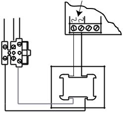
The Telecommunications Network Voltage (TNV) port (terminalsAand B on TB1) must be permanently connected (hard-wired) to the PSTN via a BT master socket, refer to Figure 3.
Note: If the BT master socket is the newer type (NTE5/CTE5), then the connection can be carried out by the installation engineer. If the BT master socket is not an NTE5/CTE5, then the network operator must make the connection.
Galaxy 2 Series PCB
BT Master socket (NTE5/CTE5).
Incoming |
2 |
|
PSTN Line |
||
5 |
A B PHONE
TB5 |
BT Master socket (NTE5/CTE5).
2 |
5 |
|
Figure 3. Connecting the Galaxy 2 Series to the PSTN |
NOTES: 1. |
Terminals 2 and 5 on the BT Master Socket must be hard-wired to theAand B terminals |
|
(TB1)on the Galaxy 2 Series PCB. The connection is polarity independent. |
2.It is strongly recommended that the Galaxy 2 Series panel is the only device on the line.
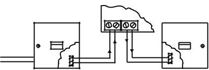
3.If another device is to be connected to the line, connect the PHONE terminals on the PCB to terminals 2 and 5 on a second BT Master Socket and connect the additional devices to the second socket.
Using cable suitable for connection to 2.8 mm diameter screw terminals, strip back approximately 20 mm of the outer sheath and then remove approximately 4 mm of the insulation from the wires to be connected to the Galaxy 2 Series.
Connect terminals 2 and 5 on the BT Master socket across theAand B terminals (TB1) on the Galaxy 2 Series, see Figure 3.
Private Branch Exchange (PBX) Approval
The Galaxy 2 Series may be used with some analogue PBX exchanges. The correct operation of the Galaxy 2 Series cannot be guaranteed under all possible conditions of connection to compatible PBXs.
9
|
Galaxy 2 Series Installation Manual |
System Wiring (cont’d) |
|
|
|
REN and SEN Numbers
It is possible to simultaneously connect a number of items to one line of the PSTN. The limit is determined by summing the Ringer Equivalence Number (REN) shown on each item of apparatus, ensuring that the sum of RENs is not more than four.
The REN of the Galaxy 2 Series is one (1).
Assume that all British Telecom equipment has a REN of one unless otherwise marked.
More than one item of series apparatus may be connected to the Galaxy 2 Series ports marked phone. This is limited by summing the Series Equivalence Number (SEN) shown on each item of series connected apparatus, ensuring that the sum of the SENs is not more than one (1). The total series resistance, including cabling, must not exceed 50 Ohms.
•The SEN of the Galaxy 2 Series is 0.3.
•Nominal series resistance is 90 milli-ohms.
•Nominal insertion loss is 0.1 dB.
It is recommended that the PSTN should have the following facilities:
•Outgoing calls only (when used as dialler only).
•Direct exchange.
•Tonedialling.
10

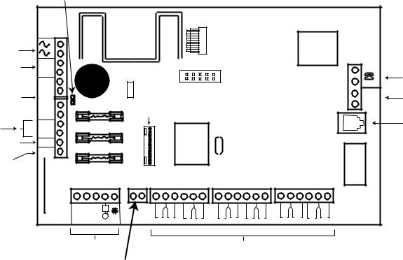
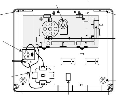
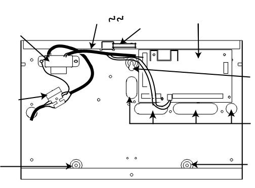
Layout PCB 44+–2 Galaxy .4 Figure 11
HEATSINK
Trigger |
|
2-way header |
Engineer |
|||
Audio |
RS485 termination |
|||||
Header |
||||||
Header |
Connector |
|
||||
|
|
|||||
|
|
|
|
|
|
|
|
|
|
|
|
|
|
F1 |
BATTERY FUSE |
|
Processor |
|
|
|
|
LK1 |
RELAY |
LED2 |
LED 1 Telecoms |
BELL FUSE |
|
|
Program |
F3 |
|
|
Header |
|
|
Alternative
Phone
Socket
F2 |
AUX FUSE |
see Note
B |
A |
B |
LINE IN |
A |
DI |
DO |
AUX+ |
AUX- |
A |
B |
AUX+ |
AUX+ |
Extension
Phone Output
Phone Line
Input
Data in |
|
|
For ECP |
Data out |
|
|
peripherals |
RS 485 peripherals
12V Aux
Output
Manual Installation Series 2 Galaxy
HARDWARE 5: SECTION
44+)–(2 Layout PCB
|
TAMPER |
|
|
|
|
|
|
|
COM N/O |
TRIG |
BELL 0v T |
|
|
1 |
2 |
3 4 |
5 6 |
7 |
8 |
9 10 |
11 12 |
N/C |
+12v |
|
|
BATT BATT |
|
|||||||||||
+ |
- |
0v |
|
0v |
0v |
0v |
|
0v |
0v |
|
|
|
|
|
|
RIO 0 |
|
|
|
RIO 1 |
|
|
|
|
|
AC power |
Battery |
|
|
|
Zone Terminals |
Loudspeaker |
SAB |
|
||||
|
|
|
Connections |
|
||||||||
|
Terminals |
|
|
|
|
|
|
|
|
|
|
|
|
|
|
|
|
|
|
|
|
|
|
|
|
|
|
Note: Switch SW1 and the |
|
|
|
Note: If Relay is fitted the TRIG terminal |
PCB |
|||||
|
|
|
|
|
is used as N/C for Relay. |
|||||||
|
|
tamper spring are for the |
|
|
|
If Relay is not fitted the COM & N/O terminals |
||||||
Tamper Spring |
|
plastic box only. |
|
|
|
|
are not fitted. The TRIG N/C terminal is |
Layout |
||||
|
The metal box has a 2-way |
|
|
|
the transistorised output. |
|||||||
and switch SW1 |
|
terminal for connection to |
|
|
|
|
|
|
|
|||
(plastic box only) |
|
the lid tamper microswitch. |
|
|
|
|
|
|
||||
|
Galaxy 2 Series Installation Manual |
PCB Layout (cont’d) |
|
|
|
PCB Layout (2–20)
|
2-way header |
|
|
|
|
|
|
|
|
|
|
|
|
|
|
|
|
RS485 termination |
|
|
|
|
|
|
|
|
|
|
|
|
|
|
|
AC Power |
|
|
|
|
|
|
|
|
|
|
|
|
|
|
|
|
Input |
|
|
|
|
|
|
|
|
|
|
|
|
|
|
|
|
Battery |
BATT + |
|
|
|
|
PROG HEADER |
|
|
|
|
|
|
|
Extension |
||
Terminals |
BATT - |
|
|
|
|
|
|
|
|
|
|
|
|
|
B |
Phone |
|
- |
|
|
|
|
|
|
|
|
|
|
|
|
|
A |
Output |
|
|
|
Power |
|
|
|
|
|
|
|
|
|
|
|
||
12 Volt |
- |
|
|
|
|
|
|
|
|
|
|
|
|
|
Phone |
|
|
|
LED |
|
|
|
|
|
|
|
|
|
|
B |
|||
Auxilliary |
AUX |
|
|
|
|
|
|
|
|
|
|
|
|
|||
|
|
|
|
|
|
|
|
|
|
|
|
|
LINE IN |
Line |
||
Output |
+ |
F1 (1 amp) |
BATT |
Trigger |
|
|
|
|
|
|
|
|
|
|
A |
Input |
|
+ |
|
|
Header |
|
|
|
|
|
|
|
|
|
|
|
|
RS 485 |
A |
F2 (0.5 amp) |
AUX |
|
|
|
|
|
|
|
|
|
|
|
|
Alternate |
lines |
B |
|
|
|
|
|
|
|
|
|
|
|
|
Phone |
||
Loudspeaker |
LS |
|
|
|
|
|
|
|
|
|
|
|
|
|
|
Socket |
|
|
|
|
|
|
X1 |
|
|
|
|
|
|
|
|
||
Negative |
TRIG |
F3 (0.5 amp) |
|
|
|
|
|
|
|
|
|
|
|
|
|
|
|
|
|
|
|
|
|
|
|
|
|
|
|
|
|||
|
(N/C) |
|
|
|
|
|
|
|
|
|
|
|
|
|
|
|
Trigger |
|
|
BELL |
|
|
|
|
|
|
|
|
|
|
|
|
|
Output |
|
|
|
|
|
|
|
|
|
|
|
|
|
|
|
|
|
|
|
|
|
|
|
|
|
|
|
|
|
|
|
|
|
|
COM N/O |
BELL 0V T |
|
1 |
2 |
3 |
4 |
5 |
6 |
7 |
8 |
9 |
10 |
11 |
12 |
|
|
|
+12v |
|
|
||||||||||||
SAB
Connections
2-way connector
Zone Terminals
Note: Switch SW1 and the |
Note: If Relay is fitted the TRIG terminal |
|
tamper spring are for the |
||
is used as N/C for Relay. |
||
plastic box only. |
||
If Relay is not fitted the COM & N/O terminals |
||
The metal box has a 2-way |
||
are not fitted. The TRIG N/C terminal is |
||
terminal for connection to |
||
the transistorised output. |
||
the lid tamper microswitch. |
||
|
Figure 5. Galaxy 2–20 PCB Layout
12
Galaxy 2 Series Installation Manual |
|
Zones |
|
|
|
Zones
The Galaxy 2–20 has 12 on-board zones expandable to 20 (RS485 bus).
The Galaxy 2–44+ has 12 on-board zones expandable to 44 (RS485 bus) or 36 (ECP bus).
The zones on the Galaxy 2 Series can function in one of three modes; Normal Closed, Double Balanced and U.S. End of line. Zone wiring for the three modes are illustrated in the following three Figures:
Figure 6. Zone wiring for Normal Closed Zones
ALARM TAMP
1K
1K
Figure 7. Zone wiring for Double Balanced Zones
1K |
Figure 8. Zone wiring for US EOL Zones
The mode of operation for the zones is programmed from menu option 51.46 = Parameters. Zone Resistance. The default zone resistors are 1k ohm. However this can be changed in option 51.46. It is strongly recommended that the maximum cable run on each zone is 100 m.
Zone Links
The bell tamper circuit can be shorted using the Links provided in the installation kit. If the zones are programmed as Double Balanced or U.S. End of Line, fit a 1k resistor across the zone and not the zone link. It is strongly recommended that this be done if any of the circuits are not to be used.
13
|
Galaxy 2 Series Installation Manual |
Wiring Zones |
|
|
|
Wiring Zones
The zones on Galaxy 2 Series panels are defaulted as double balanced. Each zone is 1 kΩ closed and 2 kΩ open. The transition from 1 to 2 kΩ generates an alarm condition. Refer to Table 2 for details of the zone resistance and resulting conditions.
NOTE: The circuit debounce time (the period the zone must remain open to register a change in condition) is 300 milliseconds by default.
Zone Resistance (ohms) |
Condition |
|
|
0-700 |
Tamper Short Circuit (TAMP S/C) |
|
|
700-1500 |
Normal (CLOSED) |
|
|
1500-11000 |
Alarm (Open) (OPEN) |
|
|
11000-infinity |
Tamper Open Circuit (TAMP O/C) |
Table 2. Zone Resistance
Multiple detectors can be wired into a single zone. The maximum number of detectors that can be connected to a single zone is 10.
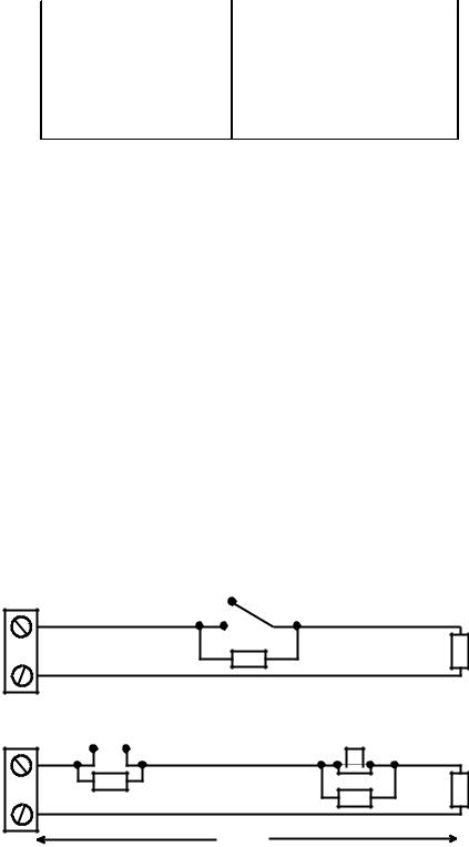
Wiring Keyswitches
The transition from 1 kΩ to 2 kΩ initiates the setting procedure of an unset system, the transition from 2 kΩ to 1 kΩ instantly unsets a set system. If the system is already set, then the transition from 1 kΩ to 2 kΩ has no effect. If the system is unset, the transition from 2 kΩ to 1 kΩ has no effect.
The wiring of the keyswitch is shown in Figure 9.
Wiring Push-Set Buttons
Zones programmed as Push-Set (terminator) buttons can be open going closed (2 kΩ to 1 kΩ) or closed going open (1 kΩ to 2 kΩ). The first activation of the terminator button initialises its status to the system.
NOTE: For push-set zones to operate, parameter 51.08, Exit Terminate, must be set up. The wiring of the terminator is shown in the following Figure .
|
1k to unset, 2k to set |
|
|
|
(only for a * keyswitch zone) |
|
|
Keyswitch |
|
1k |
|
zone |
1k |
||
1% |
|||
|
|
1%
Open - Closed |
OR |
Closed - Open |
||||||
|
|
|
|
|
|
|
|
|
|
|
|
|
|
|
|
|
|
|
|
|
|
|
|
|
|
|
|
|
|
|
|
|
|
|
|
Push-set |
1k |
zone |
1% |
|
1% |
1k |
1k |
1% |
|
|
100m
Figure 9. Keyswitch/Push-Set Zone wiring
14
Galaxy 2 Series Installation Manual |
|
Zone Addresses |
|
|
|
Zone Addresses
Each zone on the Galaxy 2 Series has a 4-digit address. For example: 1004, 1058. The address is made up of three reference numbers as shown in the following figure:
Example: 1004
1 
 00
00 
 4
4
Represents Panel |
|
|
|
Represents |
||
Represents |
|
|||||
Line No. |
RIO Address |
|
Zone No. 1-8 on |
|||
|
|
|
|
|
|
RIO/Expander |
GALAXY |
|
|
|
|
|
|
2 Series |
|
|
|
|
|
|
PANEL |
|
|
|
|
|
|
1 |
|
|
|
|
|
|
|
|
|
|
|
|
|
|
|
|
RIO |
|
ZONE 4 |
|
|
|
|
|
|||
|
|
|
ADDRESS 00 |
|
||
|
|
|
|
|
||
|
|
|
|
|
|
|
Figure 10. Zone Addresses
The example above, 1004, is the detector connected to line 1, RIO 00, zone 4.
Zone Numbering System
The numbering system is as follows:
1.The first number is the Galaxy 2 Series Panel line that the RIO/Expander is connected to. This will always be 1.
2.The next two numbers refer to the address of the RIO/Expander that the zone is on.
00 = On board RIO
01 = On board RIO
02 = RIO/Expander 1
03 = RIO/Expander 2
04 = RIO/Expander 3
05 = RIO 4
3.The last number is the actual zone on the RIO/Expander 1-8. Therefore the valid zone numbers are:
1001 - 1004
1011 - 1018
1021 - 1028
1031 - 1038
1041 - 1048
1051 - 1058
This gives a total of 44 zones.
15

|
Galaxy 2 Series Installation Manual |
Output Addresses |
|
|
|
Outputs
The Galaxy 2 Series has four on-board outputs; Bells, Strobe, Speaker and Set. The format of the addressing of the outputs is similar to zones. The addresses of these outputs are as follows:
|
|
|
|
|
|
Output |
Default |
Current (mA) |
Normal State |
Active State |
|
Address |
function |
||||
|
|
|
|||
1001 |
Set |
100 |
Off |
0V |
|
|
|
|
|
|
|
1002* |
SPK Driver |
- |
- |
- |
|
1003 |
Bell |
100 |
Off |
0V |
|
|
|
|
|
|
|
1004 |
Strobe |
100 |
Off |
0V |
|
|
|
|
|
|
Table 3. Output Addresses
*NOTE: Output 1002 - This output is configured as a 16 Ohm speaker driver (AC signal). The speaker should be connected between this output and +12V. The speaker Entry/Exit volume is controlled by parameter 51.10. It is possible to reprogram the output to operate as a normal switched negative output by programming parameter 51.15 to 0=Switch DC. However, when it is reprogrammed to operate as Switch DC, a loudspeaker should never be connected directly to this terminal otherwise damage may result.Always ensure that this parameter is set to 1=SPK Driver, before connecting a loudspeaker.
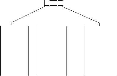
Trigger Header
The Trigger Header on the Galaxy 2 Series is a set of pins, which consists of programmable outputs for an external communication module. The connection is via an optional ribbon cable (Part No.A229).
Trig 1-8
There are eight trigger outputs, which are intended as communication triggers, but can be used for any purpose. By default these outputs are programmed as positive. They are designed to sink current (to 0V) not source current (from 12V). The addresses of these outputs are as follows:
|
|
|
|
Output |
Default |
Current (mA) |
|
Address |
function |
||
|
|||
0001 |
Fire |
100 |
|
|
|
|
|
0002 |
Panic |
100 |
|
|
|
|
|
0003 |
Intruder |
100 |
|
|
|
|
|
0004 |
Set |
100 |
|
|
|
|
|
0005 |
Omit |
100 |
|
|
|
|
|
0006 |
Not Used |
100 |
|
|
|
|
|
0007 |
Confirm |
100 |
|
|
|
|
|
0008 |
Not Used |
100 |
Table 4. Trigger Output Addresses
The function of the trigger outputs can be programmed in menu 53=Outputs.
16
Galaxy 2 Series Installation Manual |
|
Trigger Header |
|
|
|
Inputs
Line Fault: This input tells the panel that the communicator has a telephone line fault (active low). Reset: This input from the communicator resets the panel on a low to high signal (negative removed).
Supply
A100 mA, 12V output is also provided. The output is fused by the on-board AUX FUSE (F2).
+12V
Trig 8
Trig 7
Trig 6
Trig 5
Trig 4
Trig 3
Trig 2
Trig 1
Line Fault
Reset
GND
Figure 11. Trigger Header
Data Buses
Two separate data buses are available to connect the Galaxy 2–44+ panel to its peripherals.
Communication between the Galaxy 2–44+ control panel and the peripherals attached to it (see Figure 1), takes place on the data bus. The control panel constantly monitors the peripherals attached to it.Abreak in the communication from any of the peripherals generates a tamper alarm.
RS485 Wiring Configurations
The system must be wired in a daisy-chain configuration. That is the A line from the previous peripheral is connected to the A terminal of the current peripheral and then on to the A line of the next peripheral.
The RS485 (AB) line must have a 680 Ω resistor fitted across the A and B terminals of the last peripheral on the line.
|
|
GALAXY 44 V1.0 |
|
|
|
GALAXY 44 V1.0 |
|
||
|
|
09:51 |
01/08/04 |
|
|
|
09:51 |
01/08/04 |
|
|
1 |
2 |
3 |
A |
Keypad |
1 |
2 |
3 |
A |
|
|
OR |
|
||||||
|
4 |
5 |
6 |
B |
4 |
5 |
6 |
B |
|
|
7 |
8 |
9 |
ent |
Peripheral |
7 |
8 |
9 |
ent |
Galaxy 2-44 |
* |
0 |
# |
esc |
|
* |
0 |
# |
esc |
|
|
|
|||||||
Control Panel |
A |
|
|
|
B |
A |
|
|
B |
680 Ω |
A |
|
|
|
|
|
|
|
|
B |
|
|
|
|
|
|
|
|
|
|
|
|
|
|
|
|
680 Ω EOL |
||
|
|
|
|
|
|
|
|
||
Factory fitted on PCB
Figure 12. Daisy-chain Configuration
17

|
Galaxy 2 Series Installation Manual |
RS485 Wiring |
|
|
|
If two lines are connected, both ends must be terminated with 680 Ω resistors and the appropriate End OF Line (EOL) resistor on the control panel PCB must be disconnected by removal of link LK1.
|
|
|
Keypad |
|
|
|
OR |
|
GALAXY 2-44 V1.0 |
Peripheral |
|
|
09:51 |
01/08/04 |
|
1 |
2 |
3 |
A |
4 |
5 |
6 |
B |
7 |
8 |
9 |
ent |
* |
0 |
# |
esc |
A B
680 Ω EOL
Keypad
|
|
OR |
GALAXY 2-44 V1.0 |
|
|
|
|
Peripheral |
09:51 |
01/08/04 |
|
|
|
|
|
|
|
|
|
1 |
2 |
3 |
A |
|
|
4 |
5 |
6 |
B |
|
|
7 |
8 |
9 |
ent |
Galaxy 2-44 |
|
* |
0 |
# |
esc |
|
|
|
|
|
|
Control Panel |
A |
A |
|
|
B |
B
680 Ω EOL
Remove link LK1
Figure 13. TwinAB Line Daisy-Chain Configuration
RS485 Wiring Recommendations
1.The system must be wired in a daisy-chain configuration. Spur and star configurations must not be used.
2.The recommended cable used to connect the RS485 (AB) line is twisted pair screened cable (Belden 8723 equivalent). However, for cable runs of less than 100m in normal environments, standard 4-core cable can normally be used.
3.There must only be a singleAB pair of wires in each of the cables.
4.The power supply in the Galaxy 2 Series control panel and remote power supplies must not be connected inparallel.
5.The 0V of all remote power supplies must be connected in common to the 0V of the Galaxy 2 Series control panel.
6.Ensure that any extension loudspeakers are not wired in the same cable as an AB pair of wires.
7.Where possible, ensure that the AB cable is at least 30 centimetres away from any other cables.
8.Where possible, ensure that the AB cable does not run parallel to other cables for extended distances (maximum five metres).
9.The maximum length of cable run is one kilometre.
18
Galaxy 2 Series Installation Manual |
|
ECP Bus |
|
|
|
ECP Bus (2–44+ Only)
The ECP bus can operate at the same time as the RS485 bus. The cable can be standard 4-core and can be spurred or T wired.
The maximum length of cable run is 100 metres.
Galaxy 2-44 |
|
|
|
|
|
ECP Bus |
|
Keypad |
|
Control Panel |
|
|
|
OR |
Peripheral
Figure 14. ECP Line - T Wire Configuration
Built-in Dialler/Modem
The built-in dialler allows signalling to anAlarm Receiving Centre (ARC), SMS signalling and remote servicing from a PC.
LED’S
There are two LED’s on the Galaxy 2–44+ PCB. Pulsing of the red LED1 indicates an active telecommunications. Illumination of the green LED2 indicates the presence ofAC mains supply.
There is one LED on the Galaxy 2–20 PCB. Pulsing of this LED indicates an active telecommunications.
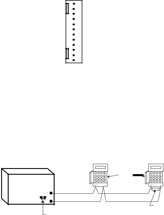
Audio Header (2–44+ Only)
This is a 14-way shrouded header for audio connection. When an alarm is received at theARC, theARC can communicate through a loudspeaker at the premises, and ask for a password before authenticating the alarm.
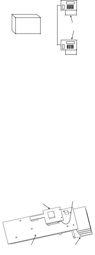
GSM Interface (2–44+ Only)
This module provides a mobile telecommunications interface to provide an alternative to the land line. The GSM interface provides the same functionality as the built-in dialler/modem. The module attaches to the underside of the PCB and also connects to the antenna on the edge of the enclosure box.
to antenna on GSM enclosure box Module
Galaxy |
Heatsink |
2-44 PCB |
|
(underside) |
|
Figure 15. GSM Module fitted to underside of Galaxy 2-44 PCB
19
|
Galaxy 2 Series Installation Manual |
Panel Mounting |
|
|
|
Panel Mounting (Plastic Box)
Installation Kit
The Galaxy 2 Series plastic box comes with an installation kit. It contains 13 zone links, a cable clamp with two self tapping screws, two M4 x 20mm lid screws, a tamper spring, battery connector leads and 24, 1K resistors.
WARNING: |
The lid of the plastic box must not be removed before isolating the mains supply. |
|
Illumination of the keypad power LED indicates the presence of a.c. mains supply. |
Removing the Enclosure Lid
1.Remove the two M4 x 20 mm pan head screws from the bottom corner of the lid.
2.Pull the lid away from the lid hinge recesses (two menus of four) on the top of the enclosure base .
3.Remove the lid.
Installing the Enclosure Lid
1.Hold the lid at an angle of 90 deg. to the enclosure base.
2.Place the eight (two menus of four) lid hinges into the recesses on the top of the enclosure base.
3.Swing the lid down making sure that the hinges fit into the holes in the top of the enclosure rim.
4.Attach the lid in place with the two M4 x 20 mm pan head screws provided.
Removing and Replacing the Galaxy 2 Series PCB
NOTE: The plastic box comes with the PCB installed. The PCB must be removed to enable access to the keyhole mounting slot (see Figure 16).
Lid Hinge
Recess
Mains Terminal Block with 200mA fuse
Secure Mains Cable After Feeding Through Entry Point
Transformer Output Lead to PCB Terminal Marked 
Lid Screw 
Keyhole
Mounting PCB
Slot
Lid Hinge
Recess
Keyhole
Mounting
Slot
Cable Entry
Points
PCB Clip |
PCB Clip |
|
|
Mounting |
|
|
Hole |
Mounting |
User Instruction |
Lid Screw |
Hole |
retaining Clip |
|
Figure 16. Galaxy 2 Series Plastic Box Layout
20
Galaxy 2 Series Installation Manual |
|
Panel Mounting (cont’d) |
|
|
|
Remove the PCB
1.Gently pull back the PCB mounting clips to free the PCB.
2.Lift the PCB free of the PCB mounting pillars.
Replace the PCB
1.Insert the PCB into the PCB mounting slots.
2.Ensure that any cabling is clear of the PCB support pillars.
3.Gently pull back the PCB mounting clips and place the PCB on top of the PCB support pillars.
4.Release the PCB mouting clips ensuring that they spring back into place and that the PCB is held firmly in place.
Mounting the Plastic Enclosure Base
Use the keyhole slot in the plastic box base to position the base. Three mounting screws (not provided) are required to mount the plastic box. Fix one of the screws into the mounting surface, this will be used for the top, keyhole mounting hole. Hang the enclosure base onto the mounting screw ensuring that the screw sits in the narrow portion of the keyhole.
All cables must be brought into the enclosure base via the cable entry points shown in Figure 16. There are six cable entry holes for the entry of alarm cables. There is one a.c. mains cable entry point located below the mains terminal block.
Fitting the Tamper Spring
The Galaxy 2 Series plastic box enclosure is supplied without the tamper spring in place. The panel will not function without a Tamper. It is therefore the engineer’s responsibility to correctly attach the tamper spring. The spring is supplied in the Installation Kit. The engineer must ensure the spring is securely attached to the Tamper Post (SW1). Refer to Figure 4.
21
|
Galaxy 2 Series Installation Manual |
Panel Mounting (cont’d) |
|
|
|
Panel Mounting (Metal Box)
Installation Kit
The Galaxy 2 Series metal box comes with an installation kit. It contains two No.8 x 12 mm self-tapping lid screws, 6160 Text Programming Overlay, two battery leads (one red and one black), 10 mm cable staple and 24, 1K resistors.
WARNING: |
The lid of the metal box must not be removed before isolating the mains supply. |
|
Illumination of the keypad power LED indicated the presence of a.c. mains supply. |
Removing and Installing the Enclosure Lid
1.Remove the two self-tapping screws that secures the lid to the enclosure base.
2.Slide the lid forward on the locating slots then lift clear.
3.To install the lid, simply reverse the process.
NOTE: The top self-tapping screw activates the Lid Tamper Microswitch.
Lid Tamper
Microswitch
Transformer
Enclosure
Earth
Connection 
Mains Terminal block
with 200mA Fuse
Mains Cable
Entry Hole
Figure 17. Galaxy 2-20 Series Metal Box Layout
NOTE: Figure 17 shows the Galaxy 2-20 in the metal box. The procedure to remove and install the Galaxy 2-44+ is identical to the 2-20.
22
Loading...