


Excel 50
CONTROLLER
HONEYWELL EXCEL 5000 OPEN SYSTEM
INSTALLATION INSTRUCTIONS
Copyright © 2009 Honeywell Inc. • All Rights Reserved |
EN1B-0101GE51 R0909G |

EXCEL 50 INSTALLATION INSTRUCTIONS
Trademark Information Echelon, LON, LONMARK, LONWORKS, LonBuilder, NodeBuilder, LonManager, LonTalk, LonUsers, LonPoint, Neuron, 3120, 3150, the Echelon logo, the LONMARK logo, and the LonUsers logo are trademarks of Echelon Corporation registered in the United States and other countries. LonLink, LonResponse, LonSupport, and LonMaker are trademarks of Echelon Corporation.
EN1B-0101GE51 R0909G |
2 |

EXCEL 50 INSTALLATION INSTRUCTIONS |
|
|
CONTENTS |
Revision Overview........................................................................................................................................................................ |
6 |
General .......................................................................................................................................................................................... |
7 |
Safety Instructions .................................................................................................... |
7 |
Hardware Overview .................................................................................................. |
8 |
Version Overview...................................................................................................... |
8 |
Dimensions............................................................................................................... |
9 |
Mounting ..................................................................................................................................................................................... |
10 |
With MMI ................................................................................................................ |
10 |
Without MMI ........................................................................................................... |
10 |
Front Door Mounting (with MMI) ............................................................................. |
10 |
Inside Cabinet Mounting (without MMI)................................................................... |
11 |
Inside Cabinet Mounting (with MMI)........................................................................ |
12 |
Application Module ................................................................................................. |
12 |
Electrical Connections............................................................................................................................................................... |
13 |
Terminal Details...................................................................................................... |
13 |
Cabling ................................................................................................................... |
13 |
Cable Routing .................................................................................................... |
13 |
Shielding ............................................................................................................ |
14 |
Cable Lengths and Cross Sectional Areas......................................................... |
14 |
Analog Inputs.......................................................................................................... |
15 |
Technical Description......................................................................................... |
15 |
Technical Specification....................................................................................... |
15 |
Pull-Up Resistor Handling .................................................................................. |
17 |
Digital Inputs........................................................................................................... |
19 |
Technical Description......................................................................................... |
19 |
Technical Specification....................................................................................... |
19 |
Connection Examples ........................................................................................ |
20 |
Analog Outputs....................................................................................................... |
20 |
Technical Description......................................................................................... |
20 |
Technical Specification....................................................................................... |
20 |
Relay Modules.................................................................................................... |
20 |
Digital Outputs ........................................................................................................ |
21 |
Technical Description......................................................................................... |
21 |
Technical Specification....................................................................................... |
21 |
Connection Examples ........................................................................................ |
21 |
Power Supply.......................................................................................................... |
21 |
CRT-Series ........................................................................................................ |
22 |
1450 Series ........................................................................................................ |
22 |
Standard Transformers ...................................................................................... |
22 |
Screw Terminal Block Installation ........................................................................... |
22 |
Adjusting the MMI Display Contrast........................................................................ |
24 |
Front Door Mounted with MMI............................................................................ |
24 |
DIN Rail Mounted with MMI................................................................................ |
24 |
Communication .......................................................................................................................................................................... |
25 |
C-Bus...................................................................................................................... |
25 |
C-Bus Termination ............................................................................................. |
25 |
Cable Specification............................................................................................. |
25 |
C-Bus Extension by Using Repeaters ................................................................ |
26 |
C-Bus Connection Procedure............................................................................. |
26 |
LONWORKS Network Interface ................................................................................. |
26 |
LONWORKS Bus Termination............................................................................... |
27 |
LONWORKS Service LED Diagnostics...................................................................... |
27 |
Controller Serial Port .............................................................................................. |
28 |
MMI Connection ................................................................................................. |
28 |
Cable Specifications........................................................................................... |
28 |
3 |
EN1B-0101GE51 R0909G |

EXCEL 50 INSTALLATION INSTRUCTIONS
Modem or ISDN Terminal Adapter Connections ................................................. |
29 |
Changing Between MMI and Modem Connection ............................................... |
29 |
Remote Communications........................................................................................................................................................... |
30 |
Modem Requirements ............................................................................................. |
30 |
No Set-Up for Standard Modem Behavior ............................................................... |
30 |
Automatic Baudrate Synchronization....................................................................... |
30 |
Auto / Manual Answer Detection ............................................................................. |
30 |
Resetting the Modem .............................................................................................. |
30 |
Set-Up for Special Modem Behavior ....................................................................... |
30 |
Set-Up for In-House Telephone Systems ................................................................ |
30 |
Set-Up for Limited Communication Speed............................................................... |
30 |
Troubleshooting....................................................................................................... |
30 |
Meter-Bus Connection (not available in N. America) ............................................................................................................... |
31 |
Meter-Bus Connection Procedure....................................................................... |
31 |
Start-Up Sequence ...................................................................................................................................................................... |
34 |
Controller Setup....................................................................................................... |
34 |
B-Port.................................................................................................................. |
35 |
C-Bus.................................................................................................................. |
35 |
LON-Bus (i.e. LonWorks Network)...................................................................... |
35 |
Meter-Bus ........................................................................................................... |
35 |
Modem Communication ...................................................................................... |
35 |
Select Application .................................................................................................... |
36 |
Request Download .................................................................................................. |
37 |
Datapoint Wiring Check........................................................................................... |
37 |
EN1B-0101GE51 R0909G |
4 |

EXCEL 50 INSTALLATION INSTRUCTIONS
5 |
EN1B-0101GE51 R0909G |

EXCEL 50 INSTALLATION INSTRUCTIONS
REVISION OVERVIEW
On the following pages, changes have been made compared to the previous release of this document:
Page: |
Change: |
|
|
39 |
Deletion of APPENDIX 1: Smoke Control. |
|
|
EN1B-0101GE51 R0909G |
6 |

EXCEL 50 INSTALLATION INSTRUCTIONS
GENERAL
•When performing any work (installation, mounting, start-up), all instructions given by the manufacturer and in particular the safety instructions provided in these Installation Instructions are to be observed.
•The Excel 50 Controller may be installed and mounted only by authorized and trained personnel.
•If the unit is modified in any way, except by the manufacturer, all warranties concerning operation and safety are invalidated.
•Make sure that certain local standards and regulations are observed at all times. Examples of such regulations are VDE 0800 and VDE 0100.
•Use only accessory equipment coming from or approved by Honeywell.
•Before the system is dismantled, disconnect the power
supply. Do this by removing the terminal block or by installing an additional 3rd-party switch onto the DIN rail close to the controller; see the following caution and note.
NOTE: The Excel 50 Controller has Pollution Degree 2, making it suitable for use in residential controls, commercial controls, in a clean environment, or nonsafety controls for installation on or in appliances.
Safety Instructions
 CAUTION
Disconnect the power supply before you start to install the Excel 50 Controller. Do not reconnect the power supply until you have completed installation.
IMPORTANT
To comply with CE requirements, devices with a voltage in the range of 50 to 1000 Vac or 75 to 1500 Vdc which are not provided with a supply cord and a plug or with other means for disconnection from the supply having a contact separation of at least 3 mm in all poles, must have the means for disconnection incorporated in the fixed wiring.
NOTE: To comply with CE requirements, the device should always be powered up using a Honeywell ETR2 or Honeywell-approved third-party transformer.
 CAUTION
Disconnect the power supply before removing or plugging in the application module.
7 |
EN1B-0101GE51 R0909G |
EXCEL 50 INSTALLATION INSTRUCTIONS
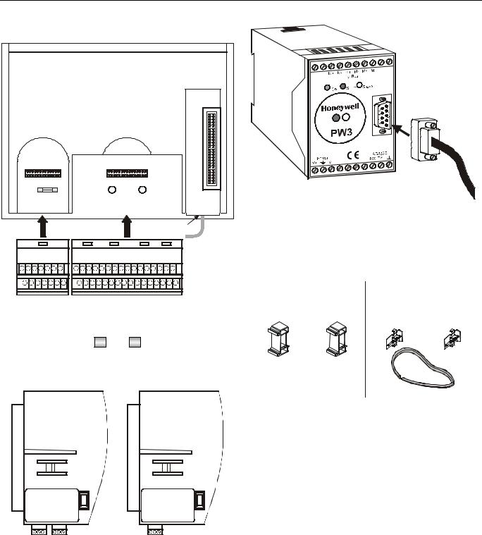
Hardware Overview |
|
|
|
|
|
|
|
port for |
|
|
|
|
application |
|
|
|
|
module |
|
port A |
|
port B |
|
XW586 |
|
|
|
|
|
fuse |
hardware adjustment |
|
|
|
(4 A, quick-acting) |
reset |
for LCD |
|
|
|
|
|
serial port |
Fig. 4. Meter-Bus adapter |
|
|
|
|
|
|
|
|
|
|
|
|
|
|
|
|
|
|
|
|
|
|
|
|
|
|
|
NOTE: The PW3 (or PW20) M-Bus adapter and XW586 M- |
|
|
|
|
|
|
|
|
|
|
|
|
|
|
|
|
|
|
|
|
|
|
Bus adapter cable are optional accessories which |
|
|
|
|
|
|
|
|
|
|
|
|
|
|
|
|
|
|
|
|
|||
|
|
block A |
|
|
|
|
|
|
|
|
block B |
|
|
|
|
|||||||
|
|
|
|
|
|
|
|
|
|
|
|
|
|
must be ordered separately. |
||||||||
|
|
|
|
|
|
|
|
|
|
|
|
|
|
|
|
|
|
|
|
|
|
|
|
|
|
|
|
|
|
|
|
|
XL50ACC2 |
|
|
|
XL50-ACC3 |
||||||
|
|
|
|
|
|
|
|
|
|
|||||||||||
|
|
|
|
|
|
|
|
|
|
(incl. in delivery) |
(ordered separately) |
|||||||||
Fig. 1. Excel 50 Controller housing (rear view) |
DIN rail mounting clips |
front-door mounting clamps |
||||||||||||||||||
|
|
|
|
|
|
|
|
|
|
|||||||||||
|
|
|
|
|
|
|
|
|
|
|
|
|
|
|
|
|
|
|
|
|
|
|
|
|
|
|
|
|
|
|
|
|
|
|
|
|
|
|
|
|
|
|
|
|
|
|
|
|
|
|
|
|
|
|
|
|
|
|
|
|
|
|
|
|
|
|
|
|
|
|
|
|
|
|
|
|
|
|
|
|
|
|
|
|
|
|
|
|
|
|
|
|
|
|
|
|
|
|
|
|
|
|
|
|
Fig. 2. Fuse, 4 A quick-acting (behind Terminal Block A)
sealing
Fig. 5. Mounting accessories
|
|
Version Overview |
|
|
|
Housing: |
|
|
|
With Man-Machine-Interface (MMI) |
|
|
|
Without MMI |
|
|
|
Application Modules: |
|
|
|
See Table 22. |
|
XD50B-FCL |
XD50-FLS |
Mounting: |
|
In cut-out of front door (requires ordering XL50-ACC3) |
|||
|
|
||
|
|
Inside cabinet, front facing DIN rail |
|
|
|
Terminals: |
|
|
|
Screw terminal blocks A + B (XS50, incl. in delivery) |
Fig. 3. Application modules (examples)
EN1B-0101GE51 R0909G |
8 |
EXCEL 50 INSTALLATION INSTRUCTIONS
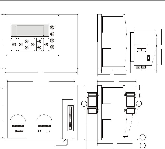
Dimensions
150
|
198 |
|
70 |
|
|
81 |
|
|
|
|
|
|
cut-out: 186 |
106 |
|
|
|
|
34 |
|
|
|
port for |
|
|
|
application |
|
|
|
module |
cut-out: 138 |
|
|
1 |
|
|
|
|
port A |
port B |
85 |
|
|
|
|
|
fuse |
hardware |
adjustment |
|
|
reset |
for LCD |
|
serial port |
97 |
|
126
Fig. 6. Dimensions
100
72
34
2
85
1 |
DIN rail clip position |
|
for models without MMI |
2 |
DIN rail clip position |
|
for models with MMI |
9 |
EN1B-0101GE51 R0909G |

EXCEL 50 INSTALLATION INSTRUCTIONS
MOUNTING
With MMI
Controllers with an MMI can be mounted either
•in the cut-out of the front door of a cabinet (the corresponding mounting kit consisting of a rubber sealing ring and front door mounting clamps is not part of the delivery and must be ordered separately; order no.: XL50-ACC3) or
•inside the cabinet on a DIN rail with the back facing towards the DIN rail (the set of DIN rail mounting clips is included in delivery; order no.: XL50ACC2.)
Without MMI
Controllers without an MMI are mounted inside the cabinet on a DIN rail with the front facing towards the DIN rail (the set of DIN rail mounting clips is included in delivery; order no.:
XL50ACC2.)
Table 1. Mounting versions
version |
mounting |
accessory |
with MMI |
in cut-out of front door |
XL50-ACC3 (not. incl.) |
with MMI |
on DIN rail in cabinet |
XL50ACC2 (incl.) |
without MMI |
on DIN rail in cabinet |
XL50ACC2 (incl.) |
Front Door Mounting (with MMI)
1.Choose the position of the controller in the front door. Observe the min. and max. distances to other devices in the front door.
2.Cut a rectangle measuring 7-21/64 in. x 5-7/16 in. (186 mm x 138 mm) out of the front door (standard DIN cutout).
Fig. 7. Front door cutout dimensions
3.Insert the rubber sealing ring into the gap around the front plate of the Excel 50 Controller.
Fig. 8. Inserting sealing ring
4.Insert the controller into the cutout in the front door.
Fig. 9. Inserting controller in front door cutout
5.Attach Front Door Mounting clamps on both sides of the controller and tighten the screws with a screwdriver as shown in Fig. 10.
EN1B-0101GE51 R0909G |
10 |

EXCEL 50 INSTALLATION INSTRUCTIONS
Inside Cabinet Mounting (without MMI)
1. Break plastic tabs covering the slots on the controller for the DIN rail mounting clips using a screwdriver.
2. Attach the DIN rail mounting clips to the housing as shown in Fig. 11.
3. Mount the controller on the DIN rail as shown in Fig. 11.
Fig. 11. Cabinet mounting without MMI
Fig. 10. Fixing controller with front door mounting clamps
11 |
EN1B-0101GE51 R0909G |

EXCEL 50 INSTALLATION INSTRUCTIONS
Inside Cabinet Mounting (with MMI)
The screw terminal blocks and the switch for the bus termination cannot be accessed after the controller with MMI is mounted on the DIN rail.
Although the bus terminal socket can still be plugged in and unplugged, it is easier to do the complete installation before mounting the controller on the DIN rail:
1.Plug in the application module as shown in Fig. 12.
2.Read the complete chapter "Installation" carefully.
3.Follow the instructions in section "Screw Terminal Block Installation Procedure".
4.Optional: Connect the C-Bus to the application module as described in section "C-Bus Connection Procedure" and/or connect the application module serial port to the Meter-Bus adapter as described in section “Meter-Bus Connection Procedure”.
5.Break plastic tabs covering the slots on the controller for the DIN rail mounting clips using a screwdriver.
6.Attach the DIN rail mounting clips at the housing as shown in Fig. 13.
7.Mount the controller on the DIN rail.
Fig. 12. Cabinet mounting with MMI
Application Module
 CAUTION
Always insert the application module before connecting the power supply.
 CAUTION
Always disconnect the power supply before unplugging the application module.
—Plug in the application module until it snaps into the controller housing.
Fig. 13. Inserting application module
NOTE: If the application module has been replaced or removed and re-inserted, please push the reset button (behind I/O terminals) after power on.
EN1B-0101GE51 R0909G |
12 |
 Loading...