

TURBO HD
720P Dome Camera
User Manual
UD.6L0201D1473A01
Thank you for purchasing our product. If there
are a ny questions, or requests , pl ea se d o no t
hesitate to cont ac t th e de al er.
This manual applies to DS-2CE56C5T-(A)VFIR and
DS-2CE56C5T-(A)VPIR3.
This manual may c ontain seve ral technical
incorrect places or printing errors, and the
content is subject to change without notice.
The updates w il l be a dd ed t o th e new version of
this manual. We will readily improve or update
the products or procedures described in the
manual.
DISCLAIMER STATEMENT
Underwriters Laboratories Inc. (”UL” has not)
tested the performance or reliability of the
security or signaling aspects of this product.
UL has only tes ted for fire, s ho ck o r ca su al ty
hazards as outlin ed i n Ul ’s Standard( s) for Safe ty,
UL60950-1. UL Certificati on d oes not co ver the
performance or reliability of the security or
signaling aspects of this product. UL MAKES N O
REPRESENTATIONS, WARRANTIES OR
CERTIFICATIONS WHATSOEVER REGARDING
0100001040603
THE PERFORMANCE OR RELIABILITY OF ANY
SECURITY OR SIGNALING RELATED FUNCTIONS
OF THIS PRODUCT.
Regulatory Information
FCC Information
FCC compliance: This equipment has been
tested and found to comply with the limits for a
digital d ev ic e, p ursuant to part 15 of the FCC
Rules. These limits are d es igned to p rovide
reasonable protection against harmful
interference when the equipment is operated in
a commercial environment. This equipment
gen erates, uses, and can radiate ra di o
frequency energy and, if not installed and used
in accordance with the instruction manual, may
cau se harmf ul i nterfer en ce to radio
communications. Operation of this equipment in
a residential area is likely to cause harmful
interference in which case the user will be
req ui red to correc t th e interfere nc e at his own
expense.
FCC Conditions
This device complies with part 15 of the FCC
Rules. Operation is subject to the following two
conditions:
1. This device may no t cause harmful
interference.
2. This device must accept any interference
received, including interference that may
cause undesired operation.
EU Conformity Statement
This prod uc t an d - if a pp lica bl e the supplied accessories too are
therefore with the applicable harmonized
Europ ea n standards l is ted under the Low Voltage
Direc ti ve 2 00 6/ 95 /EC, the EMC Directive 2004/
108/EC, the RoHS Directive 2011/65/EU.
upon the purchase of equivalent new equipment,
or dispose of it at designated collection points.
For more information see:www.recyclethis.info.
See the product documentation for specific
bat tery info rmat io n. T he b attery is marked with
this sy mb ol , wh ic h may include lette ri ng t o
indicate cadmium (Cd), lead (Pb), or mercury (Hg).
For p roper recyc li ng, re tu rn t he b attery to you r
supplier or to a designated collection point. For
more information see:www.recyclethis.info.
marked with "CE" and comply
2012/19/EC (WEEE directive):
Products marked with this symbol
cannot be disposed of as unsorted
municipal waste in the European
Union. For proper recycling, return
this product to your local supplier
2006/66/EC (battery directive):
This product contains a battery
that cannot be disposed of as
unsorted municipal waste in the
European Union.
1 Introduction
1.1 Product Features
This camera adopts new generation sensor with
high sensitivity and advanced circuit board design
technology. It possesses the features of high
resolution, low distortion, and low noise, etc. It is
extremely suitable for supervisory system and
image processing system.
The main features are as follows:
l
High performance CMOS sensor and high
resolution bring high-quality image;
l
Low illuminat io n, 0.01 Lux @ (F1.2, AGC O N) ,
0 Lux with IR;
l
Support IR cut filter with auto switch;
l
OSD menu, param eters are configurable;
l
Support auto white balance, auto gain control,
electronic shutter control and internal
synchronization;
l
Advanced engineering design and patent
universal adjustable structure provides
convenient adjustment and high reliability;
lSMART IR mode;
l
Unit transmission control;
l
Advanced 3-axis design meets different
installation requirements;
l
Ingress protection: IP66.
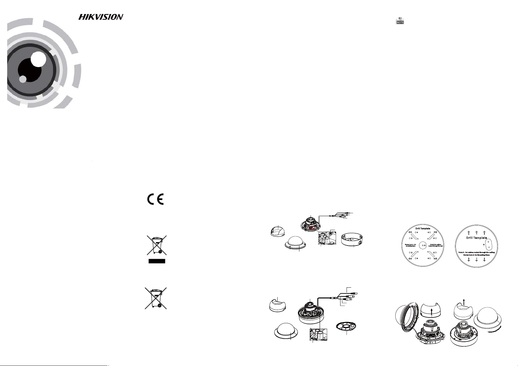
1.2 Overview
1.2.1 Over view of Type I Dome Cam era
Lens
Black Liner
Auxiliary Video Output
Bubble
Figure 1- 1 Ov er vi ew o f Typ e I Do me C am era
1.2.2 Overview of Type Dome CameraII
Black Liner
Figure 1- 2 Ov er vi ew o f Typ e Dome CameraII
Dip Switch
Bubble
Auxiliary Video Output
Lens
HD Vi deo Cab le
CVBS Cable
Dip Switch
Back Box
Powe r Cable
CVBS Cable
HD Video Cable
Base plate
Power Ca ble
The HD video output mode is set as the defa ul t.
You can press the dip switc h to switch the mode
as CVBS output.
2 Installation
Before you start:
l Please make sure that the devi ce i n the package
is in good condition and all the assembly parts
are i nc lu de d.
l Make sure that all the rel ated equipment is
power-off during the installation.
l Check the specificati on o f th e prod uc ts for the
installation environment.
l Check whether the power s up pl y is m atched
with yo ur p ow er o ut pu t to avoid damage .
l Please make sure the wal l is s trong enough to
withstand three times the weight of the camera
and the mounting.
l If the wa ll i s th e ce me nt wall, you need to insert
exp an si on s cr ews before you insta ll t he camera.
If the wa ll i s th e wo od en wall, you can use
self-ta pp in g screw to secure the camera.
l If the product does not function properly,
please contact your dealer or the nearest
service cente r. Do no t di sa ss em bl e th e ca me ra
for repair or maintenance by yourself.
2.1 Ceiling Mounting
Steps:
1.Drill the scre w ho le s an d th e ca bl e ho le o n th e
ceiling according to the supplied drill template.
Type I:
Figure 2-1 The Drill Template
.
2 Loosen the screws on the bubble of type 1
cam era /rota te the bubble of t yp e2 camera to
rem ove the bubb le a nd t he b la ck l in er.
Type I:
Figure 2- 2 Remove the Bubble
Type I :I
Type I :I
3.Attach the back box o f ty pe 1 camera /base plate
of type2 camera to the ceiling and secure them
with supplied self-tapping screws.
4.Rou te the cables through the cab le hole.
5.Align the camera with the back box/base plate,
and tighten t he s et s crews to se cu re t he camera
with the back box/base plate.
Type I:
Type I :IType I :IType I :I
Figure 2- 3 Fi x th e Ca me ra
6. Connect the corresponding cables.
7. Adjust t he c am era accordi ng t o th e fi gu re below
to get an o ptimum a ng le
8. Fit the black liner on the camera an d ti ghten the
screws on the b ub bl e of t yp e 1 camera or rotate the
bubble of type 2 camera to complete.
Type I:
0~90°°
T Direction
R Direction
P Direction
0 ~355°°
Type I :I
T Direction
0 ~355°°
0~90°°
0°~355°
R Direction
0 ~340°°
P Direction
Figure 2- 4 Zoom and Focus Adjustment
2.2 In-ceiling Mounting
You need to purchase an in-ceiling mount separately
if you adopt in-celling mounting.
Steps:
1.Drill the scre w ho le s an d th e ca bl e ho le i n th e
ceiling according to the supplied drill template.
2.Screw the bolts through the mount by aligning
with the 2 bolt holes. Fit the toggles onto t he bolts.
3.Push the two to ggle bolts throu gh t he t wo s crew
holes on the ceiling. Rotate the bolt till the toggle
holds the ceiling tightly.
Figure 2-5 Install the In-ceiling Mount
4.Route and connect the corresponding cables.
5.Fix the camera to the in-ceiling mount with the
supplied screws.
Type I:
Type I :I
Figure 2- 6 Fi x th e Ca me ra to the Mount
6. Repeat steps 6-8 of the Ceiling Mounting section
to complete the installation.
2.3 In-ceiling Mounting with
Gang Box
Only the type 1 camera supports the in-ceiling
mounting with gang box.
1.Repeat steps 2-3 of the In-ceiling Mounting
section to secure the in-ceiling mount (supplied)
to the gang box.
Figure 2- 7 In stall The Mount
2.Route and connect the corresponding cables.
3.Align the camera wi th t he gang box , and tighte n
the screws to secure the camera with the gang box ..
Figure 2- 8 Fi x th e Ca me ra to the Gang Box
4. Repeat steps 6-8 of the Ceiling Mounting section
to complete the installation.
3 Menu Operation
MENU
MAIN
VIDEO
STANDARD
WB
DAY
&NIGHT
COLOR
B/W
SMART
AE
BRIGHTNESS
AE MODE
AGC
SENSE UP
AUTO
MANUAL
Figure 3-1 Main Menu
You can call the menu and adjust the ca me ra
parameters with a coaxial camera controller
(purc ha se s ep arately). You can also call the menu
with supported TVI DVR.
MENU
VIDEO
SETTING
CONTRAST
SHARPNESS
COLOR
GAIN
3D NR
MIRROR
LANGUAG E
FUNCTION
DETECTION
MASKING
ZOOM IN
RESET
SAVE
&EXIT
3.1 AE
Move th e cu rsor to AE, and you can adjust th e
image b ri ghtn es s by t he , ,BRIGHTNESS AE MODE
AGC SENS-UP, and in this menu.
As shown in Figure 3- 2.
.
BRIGHTNESS: Set t he b ri ghtn es s value from
1 to 10 t o da rken or brighte n th e im age.
: Set AE mode as GLOB LE A E, a ndAE MODE
D-WDR.
AGC HIGH MIDDLE LOW: , , and can be s et for the
AGC level. Select OFF to disable the AGC.
: Set the SENSE UP va lu e from 0 to 16.SENSE UP
AE
1. BRIGHTNESS 1-|--10
2. AE MODE DWDR
3. AGC OFF
4. SENSE UP 0-|---16
5. RETURN 8
Figure 3-2 AE
MANUAL
1. R GIAN 1-|--10
2. B GAIN 1-|--10
3. RETURN 8
Figure 3-3 WB-Manual
3.2 WB
Move th e cu rsor to WB, and you c an s et White
Balance mode as and in this menuAUTO MANUAL .
AUTO: white balance is being adjusted
automatically.
: Set the val ueMANUAL R GAIN/B GAIN
fro m 1 to 10. As sh own in Fig ure 3-3.
3.3 DAY & NIGHT
Move the cursor to DAY & NIGHT, and select
COLOR B/W SMART, , or as the DAY & NIGHT mode.
COLOR: The image is colore d in d ay mode all the
time.
: The image is black & white all the time, andB/W
the IR LED turns on in the low-light co nd itions.
: Select to turn on/off the INFRARED_LAMPSMART
and to se t th e Sm ar t IR l evel from 1to 16.
As shown in Figure 3- 4.
SAMRT
1. INFRARED_LAMP OFF
2. SMART IR 0-|--5
3. RETURN 8
Figure 3- 4 Sm ar t Mo de o f DAY&NIGHT
3.4 Video Setting
Move th e cu rsor to the VIDEO SETTING, and press
the menu butt on to enter the video confi gu ration
int er face. As shown in Figure 3-5.
: Set the CON TR AS T value from 1 to 1 0.CONTRAST
val ue f rom 1 to 10.
COLOR GAIN: Set t he c ol or gain from 1 to 1 0.
and . Select to disable the 3D NR.Low OFF
, or .VHV
: Set the edge an d de tail sharpne ssSHARPNESS
: Set the 3D NR lev el a s , ,3D NR High Middle
: Set the mirro r mo de a s , ,MIRROR OFF H
3.5 FUNCTION
You can set , , an dDETECTION MASKING ZOOM IN
1. CONTRAST 1-|-- 10
2. SHARPNESS
3. COLOR GAIN 1-|--10
4. 3D NR OFF
5. MIRROR OFF
6. RETURN
Figure 3- 5 Vi de o Se ttings
DETECTION: Set the motion sensitivity as
ent er t he m ot io n de tection AREA menu. As shown
in Figure 3-7.
are a bo rder. Move the joystick up/ down and r ig ht
/left t o se t th e ho ri zon/vertica l si ze and position.
As shown in Figure 3- 8.
1. SENSITIVITY HIGHT
2. AREA NO.0
3. AREA NO.1 8
4. AREA NO.2 8
5. AREA NO.3 8
6. RETURN 8
Figure 3-7 Detection
MASKING: Select a masking back ground color.
Select an AREA to enter the masking AREA menu.
As shown in figure 3- 9.
up/down and right/left to set the horizon/vertical
size and position.
As shown in Figure 3-10.
1. COLOR WHITE
2. AREA NO.0
3. AREA NO.1 8
4. AREA NO.2 8
5. AREA NO.3 8
6. AREA NO.4 8
7. AREA NO.5 8
8. AREA NO.6 8
9. AREA NO.7 8
10.RETURN 8
Figure 3-9 Detection Area
ZOOM IN: The ZOOM IN value can be adjusted from
50 to 100.
LANGUAGE: Chinese and English are selectable.
of the camera in this men u.LANGUAGE
VIDEO SETTING
8
8
1. DETECT ION
2. MASKING 8
3. ZOOM IN 50-|--100
4. LANGUAGE ENGLISH
5. RETURN
Figure 3-6 Function
, , or . Select an AREA toWEAK LOW MIDDLE HIGH
: Set the status as / . Select a color forAREA OFF ON
DETECTION
8
1. STATUS OFF
2. COLOR
3. HORIZON SIZE 0
4. VERTICAL SIZE 0
5. HORIZON MOVE 0
6. VERTICAL MOVE 0
7. RETURN
Figure 3-8 Detection Area
: Set the status as / . Move the joystickAREA OFF ON
MASKING
8
1. STATUS OFF
2. HORIZON SIZE 0
3. VERTICAL SIZE 0
4. HORIZON MOVE 0
5. VERTICAL MOVE 0
6. RETURN
Figure 3-10 Detection
FUNCTION
AREA
AREA
8
8
WHITE
8
8
3.6 Reset
Res et a ll t he s ettings to the default.
3.7 Save & Exit
Move th e cu rsor to , and pre ss O K toSAVE & R ESET
save the settings and ex it t he m en u.
 Loading...