

TURBO HD
1080P Dome Camera
User Manual
UD.6L0201D1548A01
Thank you for purchasing our product. If there
are a ny questions, or requests, please do not
hesita te to conta ct th e dealer.
This manual applies to DS-2CE56D5T-(A)VFIR and
DS-2CE56D5T-(A)VPIR3.
This manual may co ntain severa l tec hni cal
incorrect places or printing errors, and the
content is subject to change without notice.
The updates w ill b e added to t he new version of
this manual. We will readily improve or update
the products or procedures described in the
manual.
DISCLAIMER STATEMENT
Underwriters Laboratories Inc. (”UL” has not)
tested the performance or reliability of the
security or signaling aspects of this product.
UL has only tested for fire, shock or casualty
hazards as ou tli ned i n Ul’s Standard(s) for Sa fety,
UL60950-1. UL Certification does not cover the
performance or reliability of the security or
signaling aspects of this product. UL MAKES NO
REPRESENTATIONS, WARRANTIES OR
CERTIFICATIONS WHATSOEVER REGARDING
0100001040603
THE PERFORMANCE OR RELIABILITY OF ANY
SECURITY OR SIGNALING RELATED FUNCTIONS
OF THIS PRODUCT.
Regulatory Information
FCC Information
FCC compliance: This equipment has been
tested and found to comply with the limits for a
digita l dev ice, pursua nt to part 15 of th e FCC
Rules. These limits are designed to pro vid e
reasonable protection against harmful
interference when the equipment is operated in
a commercial environment. This equipment
gen erates, uses, and can ra dia te radio
frequency energy and, if not installed and used
in accordance with the instruction manual, may
cau se harmful inter fere nce to radio
communications. Operation of this equipment in
a residential area is likely to cause harmful
interference in which case the user will be
req uir ed to correct the interference at his own
expense.
FCC Conditions
This device complies with part 15 of the FCC
Rules. Operation is subject to the following two
conditions:
1. This device may n ot ca use h arm ful
interference.
2. This device must accept any interfere nce
received, including interference that may
cause undesired operation.
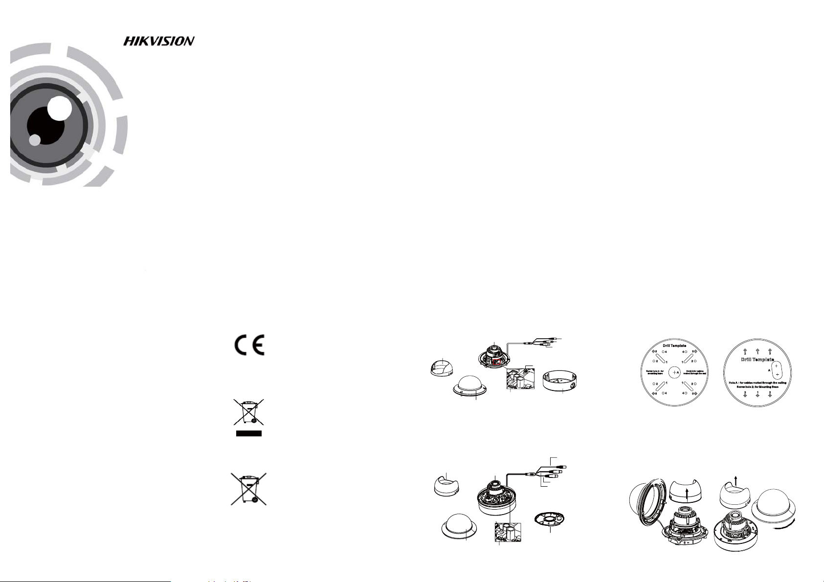
EU Conformity Statement
This product and - if applicable - the
supplied accessories too are marked
with "CE" and comply therefore with
the applicable harmonized European
standa rds listed under the Low Volta ge Di rective
2006/95/EC, the EMC Directive 2004/108/EC,
the RoHS Directive 2011/65/EU.
2012/19/EU (WEEE directive):
Products marked with this symbol
cannot be disposed of as unsorted
municipal waste in the European
Union. For proper recycling, return
upon the purchase of equivalent new equipment,
or dispose of it at designated collection points.
For more information see:
See the product documentation for specific
bat tery information. The batter y is ma rked with
this sym bol , which may inc lud e lettering to
indicate cadmium (C d), l ead ( Pb) , or mercu ry (Hg).
this product to your local supplier
www.recyclethis.info.
2006/66/EC (battery directive):
This product contains a battery that
cannot be disposed of as unsorted
municipal waste in the European
Union.
For p roper recycling, return the batte ry to your
supplier or to a designated collection point. For
more information see: www.recyclethis.info.
1 Introduction
1.1 Product Features
This camera adopts new generation sensor with
high sensitivity and advanced circuit board design
technology. It possesses the features of high
resolution, low distortion, and low noise, etc. It is
extremely suitable for supervisory system and
image processing system.
The main features are as follows:
l
High performance CMOS sensor and high
resolution bring high-quality image;
l
Low illumination;
l
Support IR cut filter with auto switch;
l
OSD menu, parame ters are co nfi gurable;
l
Support auto white balance, auto gain control,
electronic shutter control and internal
synchronization;
l
SMART IR mode;
l
Unit transmission control;
l
Advanced 3-axis design meets different
installation requirements.
1.2 Overview
1.2.1 Over view of Type I Dome Camera
Lens
Black Liner
Auxiliary Video Output
Bubble
Figure 1 -1 Ov erview of Type I Dome Camera
1.2.2 Over view of Type Dome Camera
Black Liner
Figure 1 -2 Ov erview of Type Dome CameraII
Dip Switch
Bubble
Auxiliary Video Output
Lens
II
HD Vi deo Cab le
CVBS Cable
Dip Switch
Back Box
Powe r Cable
CVBS Cable
HD Video Cable
Base plate
Power Cab le
2 Installation
Before you start:
l Please make sure that the device in the package
is in good condition and all the assembly parts
are i ncl uded.
l Make sure that all the rel ated equ ipm ent i s
power-off during the installation.
l Check the specification of the products fo r the
installation environment.
l Check whether the power supply is matched
with you r power ou tput to avoid damage.
l Please make sure the wall is stron g eno ugh t o
withstand three times the weight of the camera
and the mounting.
l If the wall is the cement wall , you n eed to ins ert
exp ans ion scre ws before you install the camera.
If the wall is the wooden wall, you can use
self-tapping scre w to se cure the camera.
l If the product does not function properly,
please contact your dealer or the nearest
service center. Do not disassemble the camera
for repair or maintenance by yourself.
2.1 Ceiling Mounting
Steps:
1.Drill the screw h oles and the cable hole on the
ceiling according to the supplied drill template.
Type I:
Figure 2-1 The Drill Template
.
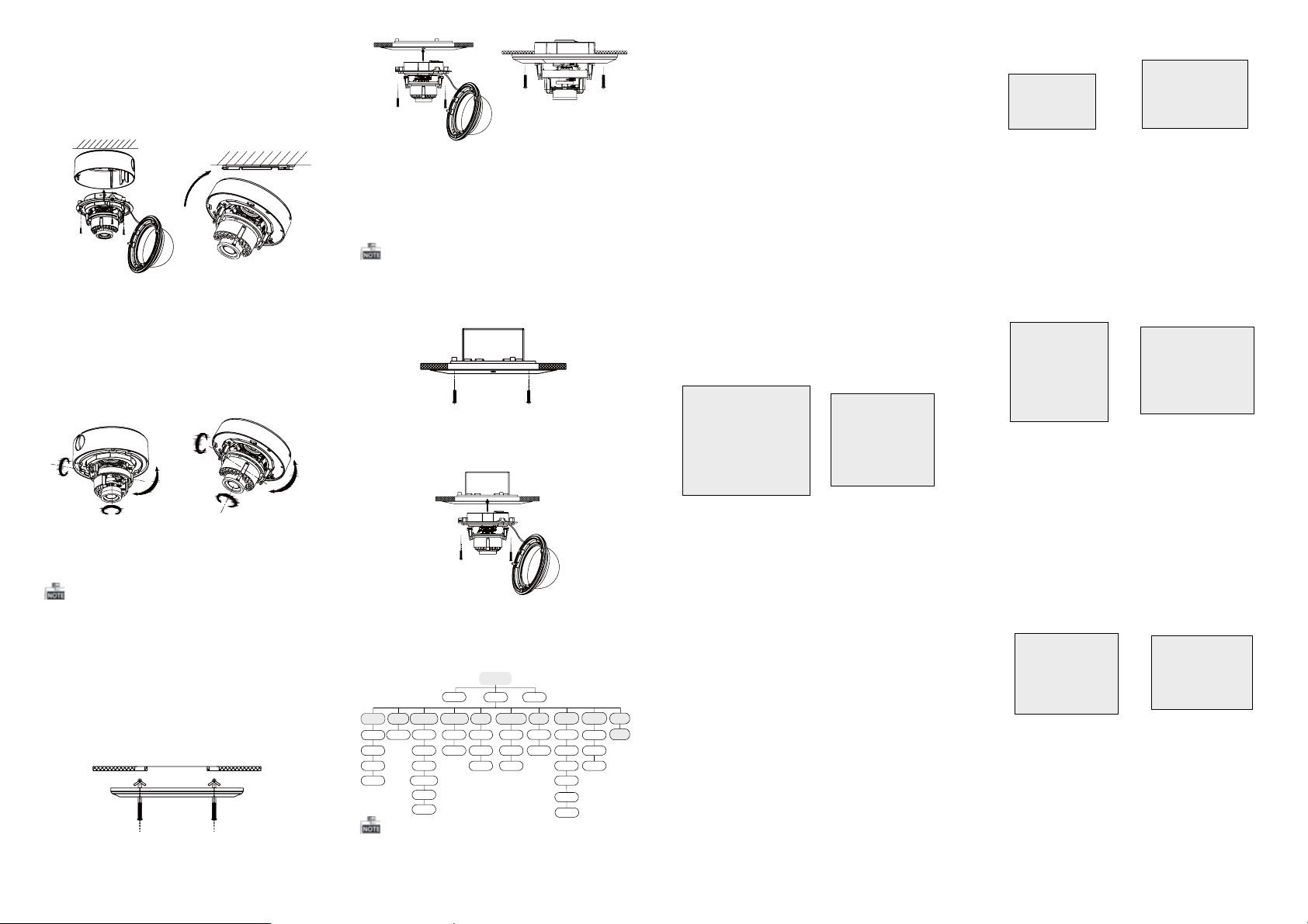
2 Loosen the screws on the bubble of type 1
cam era /rotate th e bub ble o f typ e2 ca mera to
rem ove the bu bbl e and t he black liner.
Type I:
Figure 2-2 Remove the Bubble
Type I :I
Type I :I
3.Attach the back box of ty pe 1 ca mera /base pl ate
of type2 camera to the ceiling and secure them
with supplied self-tapping screws.
4.Route the cables th rough the cable hole.
5.Align the camera wit h the b ack box/ bas e pla te,
and tighten t he se t scr ews to secure the camera
with the back box/base plate.
Type I:
Type I :IType I :IType I :I
Figure 2-3 Fix the Camera to the Ceiling
6. Connect the corresponding cables.
7. Adjust the camera according to the figure below
to get an op tim um an gle .
8. Fit the black liner on the camera and tighten t he
screws on the bubble of type 1 camera or rotate the
bubble of type 2 camera to complete.
Type I:
0~90°°
T Direction
R Direction
P Direction
0 ~355°°
Type I :I
T Direction
0 ~355°°
0~90°°
0°~355°
R Direction
0 ~340°°
P Direction
Figure 2 -4 Zo om an d Focus Ad justme nt
2.2 In-ceiling Mounting
You need to purchase an in-ceiling mount separately
if you adopt in-celling mounting.
Steps:
1.Drill the screw h oles and the cable hole in the
ceiling according to the supplied drill template.
2.Screw the bolts through the mount by aligning
with the 2 bolt holes. Fit the tog gle s onto the bolts.
3.Push the two toggle bolts through the two screw
holes on the ceiling. Rotate the bolt till the toggle
holds the ceiling tightly.
4.Route and connect the corresponding cables.
5.Fix the camera to the in-ceiling mount with the
supplied screws.
Figure 2 -5 Install th e Mou nt
Type I:
Type I :I
Figure 2 -6 Fi x the Camera to the Mo unt
6. Repeat steps 6-8 of the Ceiling Mounting section
to complete the installation.
2.3 In-ceiling Mounting with
Gang Box
Only the type 1 camera supports in-ceiling
mounting with gang box.
1.Repeat steps 2-3 of the In-ceiling Mounting
section to secure the in-ceiling mount (supplied)
to the gang box.
Figure 2 -7 Install th e Mou nt
2.Route and connect the corresponding cables.
3.Align the camera wi th the gan g box, and tighten
the scre ws to secure the camera wi th the gan g box..
Figure 2 -8 Fi x the Camera to the Ga ng Box
4. Repeat steps 6-8 of the Ceiling Mounting section
to complete the installation.
3 Menu Operation
Menu
VIDEO.
OUT
BACKLIGHT
EXPOSURE
SCENE
INDOOR
OUTDOOR
INDOOR1
LOWLIGHT
LENS
MANUAL
SHUTTER
AGC
SENS-UP
BRIGHTNESS
D-WDR
DEFOG
HSBLC
WB
BLC
ATW
AWC-SET
MANUAL
Figure 3-1 Main Menu
You can call the menu and adjust the camera
parameters with a coaxial camera controller
(purch ase separately). You ca n als o cal l the m enu
with supported TVI DVR.
SETUP
DAY&NIGHT
COLOR
B/W
EXT
LAUGUAGE
2D NR
3D NR
ADJUST
SPECIAL
NR
CAM
TITLE
D-EFFECT
MOTION
PRIVACY
DEFECT
VERSION
SHARPNESS
MONITOR
LSC
RESET
EXIT
3.1 VIDEO.OUT
PAL or NTSC is selectable .
3.2 LANGUAGE
English, Japanese, CHN1, C HN2 , Korean, German,
French, Italian, Spanish, Polish, etc., are selectable.
3.3SETUP
3.3.1 SCENE
You can select indoor, outdoor, indoor 1 and low
-light as the working envi ronments.
3.3.2 LENS
The camera is e qui ppe d wit h a fixed lens.
3.3.3 EXPOSURE
SHUTTER: AUTO,1/25, 1/50, FLK, 1/200, 1/400,
1/1k, 1/2k, 1/5k, 1/10k, 1/5 0k, x 2, x4 , x6, x 8, x1 0,
and x15 are selectable.
: You can set the AGC valu e fro m 0 to 15.AGC
: You can set the SENS-UP to OFF or AUTO.SENS-UP
: You can set the brightness valueBRIGHTNESS
fro m 1 to 10 0.
: You can set the defog fu nct ion as ON toDEFOG
enable the function. Position, size, and the defog
gradation are configurable.
You can set the D-WDR as ON or OFF.D-WDR:
EXPOSURE
1. SHUTTER AUTO
2. AGC OFF
3. SENS-UP ---
4. BRIGHTNESS ---|------ 40
5. DEFOG OFF
6. D-WDR OFF
7. RETURN RET
Figure 3-2 Exposure
HSBLC
1. SELECT AREA 1
2. DISPLAY ON 8
3. LEVEL ---|------ 40
4. MODE ALL DAY
5. BLACK MASK ON
6. DEFAULT 8
7. RETURN RET
Figure 3 -3 HSBLC
3.3.4 Backlight
Backlight Compensation (BLC):
Set the ga in of B LC as H igh , Mid dle , or Low.-GAIN:
Press the up/down/left/right button to-AREA:
define the BLC position and size. Select RET or
AGA IN to g o bac k the B LC me nu or re-d efine the
BLC a rea .
Restore the BLC settin gs to the default.-Default:
HSBLC: Select an HSBLC area. Set the DISPLAY
status as ON. Press the up/down/left/right button
to de fin e the a rea p osi tio n and size. Set the HSBLC
LEVEL from 0 to 100. Select ALL DAY or Night for the
HSBLC mode. Set the BLACK MASK status as ON or
OFF.
3.3.5 White Balance (WB)
MANUAL, ATW (Auto-tracking White Balance),
AWC→SET are selectable.
3.3.6 Day & Nig ht
Color, B/W, and EXT are selectable for DAY and
NIGHT switches.
3.3.7 NR
: You can set 2D NR sta tus a s ON or O FF.2D NR
: Set the Smart NR status as ON and adjust3D NR
the 3D smart NR sensitivity ranges from 0 to 100 .
Set the 3D NR LEVEL ra nge s from 0 to 100. Set the
START. AGC l evel as the threshold to enable AGC,
and set the END. AGC level as the threshold to
disable AGC.
2D&3D NR
1. 2DNR OFF
2. 3DNR ON
3. RETURN RET
Figure 3 -4 NR
8
3D NR
1. SMART NR ON
2. LEVEL ------|--8 0
3. START. AGC -|--------10
4. END. AGC -|--------10
5. RETURN RET
8
Figure 3 -5 3D NR
3.3.8 SPECIAL
Edi t the c ame ra title on this sec tio n.Camera Title:
D-effect:
Set the freeze function as ON or OFF.-FREEZE:
OFF, MIRROR , V-F LIP, and ROTATE are-MIRROR:
selectable for mirror.
Define the zoom area by configuring-D-ZOOM:
the position from PAN & TILT.
The D-Zoom area, sensitivity-SMART D-ZOOM:
and time are configurable.
Set the NEG IMA GE as O N or OF F.-NEG.IMAGE:
SPECIAL
1. CAM TITLE ON
2. D-DFFECT 8
3. MOTION OFF
4. PRIVACY O FF
5. LANGUAGE ENG
6. DEFECT 8
7. RETURN RET
8
8
Figure 3-6 Special
Figure 3 -7 Motion Detect ion
MOTION
1. SELECT AREA 1
2. DISPLAY ON8
3. SENSITIVITY ----|---- 30
4. MOTION VIEW ON
5. DEFAULT 8
6. RETURN RET
Motion: Select a MOTION area. Set the DISPLAY
status as ON or OFF. Press the up/down/left/right
button to define the posit ion a nd si ze of the area.
Set the SENSITIVITY from 0 to 60. Set th e MOTION
VIEW status a s ON or O FF.
Privacy: Select a PRIVACY area. Set the DISPLAY
status as INV, MO SAI C, COLOR or OFF. Pre ss th e
up/down/left/right button to define the position
and size o f the a rea .
Defect: LIVE DPC, STATIC DPC and Black DPC are
adjustable in this section.
PRIVACY
1. SELECT AREA 1
2. DISPLAY MOSAIC
3. COLOR 10
4. TRANS. 1
5. DEFAULT
6. RETURN RET
8
8
Figure 3-8 Privacy Mask
ADJUST
1. SHARPNESS --------|1 5
2. MONITOR LCD8
3. LSC OFF
4. RETURN RET
Figure 3-9 Adjust
3.3.9 ADJUST
: Adjust the sharpness from 0 to 15.Sharpness
: Monitor CRT, and Monitor LCD areMonitor
selectable.
: Set the LSC status as ON or O FF.LSC
3.3.10 RESET
Res et al l the s ettings to the defa ult .
3.3.11 EXIT
Pre ss OK t o exit the menu .
 Loading...