


Graco 230V, 287512, 360G-287513, 1895-287928, CPG User Manual
...Repair
Displacement Pump |
310894G |
|
-For portable spray application of architectural paints and coatings or replacement pump for Graco GMaxt II sprayers -
3300 psi (228 bar, 22.8 MPa) Maximum Working Pressure
Model 287512, Series A
GMax II 3900 Sprayer, Rental Pro 360G
Model 287513, Series A
GMax II 5900 Sprayer,
UltraMax II 1095/1595 with ProConnect
Model 287579, Series A
GMax II 5900HD Sprayer
Model 249122, Series A
GMax II 7900 Sprayer, Ultra Max II 1895
Model 287928, Series A
Mark Vt International
Model 287929, Series A
Mark V North America
Model 289590, Series A
TexSpray 7900HD, Mark X, 230V, Domestic
ti6177a
Important Safety Instructions
Read all warnings and instructions in this manual and in your sprayer manual. Save these
instructions.
GRACO INC. P.O. BOX 1441 MINNEAPOLIS, MN 55440-1441
Copyright 2005, Graco Inc. is registered to I.S. EN ISO 9001
Table of Contents
Warnings . . . . . . . . . . . . . . . . . . . . . . . . . . . . . . . . . . . . . |
. 2 |
287579 . . . . . . . . . . . . . . . . . . . . . . . . . . . . . . . . . . . . . |
13 |
Service . . . . . . . . . . . . . . . . . . . . . . . . . . . . . . . . . . . . . . . |
3 |
287928 . . . . . . . . . . . . . . . . . . . . . . . . . . . . . . . . . . . . . |
14 |
Technical Data . . . . . . . . . . . . . . . . . . . . . . . . . . . . . . . . . |
9 |
287929 . . . . . . . . . . . . . . . . . . . . . . . . . . . . . . . . . . . . . |
15 |
Parts, Pump |
|
289590 . . . . . . . . . . . . . . . . . . . . . . . . . . . . . . . . . . . . . |
16 |
287512 . . . . . . . . . . . . . . . . . . . . . . . . . . . . . . . . . . . . . |
10 |
Warranty . . . . . . . . . . . . . . . . . . . . . . . . . . . . . . . . . . . . . |
18 |
287513 . . . . . . . . . . . . . . . . . . . . . . . . . . . . . . . . . . . . . |
11 |
Graco Phone Number . . . . . . . . . . . . . . . . . . . . . . . . . . |
18 |
249122 . . . . . . . . . . . . . . . . . . . . . . . . . . . . . . . . . . . . . |
12 |
|
|
Warnings
Warning Symbol
 WARNING
This symbol alerts you to the possibility of serious injury or death if you do not follow the instructions.
Caution Symbol
CAUTION
This symbol alerts you to the possibility of damage to or destruction of equipment if you do not follow the instructions.
 WARNING
EQUIPMENT MISUSE HAZARD
Misuse can cause death or serious injury.
INSTRUCTIONS D Do not exceed the maximum working pressure temperature rating of the lowest rated system component. See Technical Data in all equipment manuals.
DUse fluids and solvents compatible with equipment wetted parts. See Technical Data in all equipment manuals. Read manufacturer fluid and solvent warnings.
D Check equipment daily. Repair or replace worn or damaged parts immediately. D Do not alter or modify equipment.
D Read all instruction manuals, tags, and labels before operating the equipment.
D Use equipment only for its intended purpose. Call your Graco distributor for information.
DDo not use 1,1,1--trichloroethane, methylene chloride, other halogenated hydrocarbon solvents or fluids containing such solvents in pressurized aluminum equipment. Such use could result in a chemical reaction, with the possibility of explosion.
D Comply with all applicable safety regulations.
MOVING PARTS HAZARD
Moving parts can pinch or amputate your fingers.
D Keep clear of moving parts.
D Do not operate equipment with protective guards or covers removed.
DPressurized equipment can start without warning. Before checking, moving or servicing equipment, follow the Pressure Relief Procedure on page 3. Disconnect power cord.
2 310894
Service
Pressure Relief Procedure
 WARNING
PRESSURIZED EQUIPMENT HAZARD
The system pressure must be manually relieved to prevent the system from starting or spraying accidentally. To
reduce the risk of an injury from accidental spray from the gun, splashing fluid, or moving parts, follow the Pressure Relief Procedure whenever you:
D are instructed to relieve the pressure, D stop spraying,
D check or service any of the system equipment,
D or install or clean the spray nozzle.
1.Lock gun trigger safety.
2.Turn engine ON/OFF switch to OFF.
3.Move pump switch to OFF and turn pressure control knob fully counterclockwise.
4.Unlock trigger safety. Hold metal part of gun firmly to side of grounded metal pail, and trigger gun to relieve pressure.
5.Lock gun trigger safety.
6.Open pressure drain valve. Leave open until ready to spray again.
If you suspect that the spray tip or hose is completely clogged, or that pressure has not been fully relieved after following the steps above, VERY SLOWLY loosen tip guard retaining nut or hose end coupling to relieve pressure gradually, then loosen completely. Now clear tip or hose.
Pump Repair Kits
Pump |
Repair Kit |
|
|
287512 |
248212 |
|
|
287513 |
248213 |
|
|
287579 |
248213 |
|
|
249122 |
249123 |
|
|
287928 |
249189 |
|
|
287929 |
248213 |
|
|
289590 |
249123 |
|
|
Tools Needed
Vise
12 in. adjustable, open end wrench (2) Hammer, 20 oz maximum
Small screwdriver Throat Seal Liquid
Pick or long small screwdriver
Cleaning and Inspecting Parts
1.Clean and inspect parts. Pay particular attention to the ball seats in the intake valve and piston, which must have no nicks or wear, and to the inside of the sleeve and the outside of the piston rod, which must not be worn or scratched. Replace worn or damaged parts.
 WARNING
COMPONENT RUPTURE HAZARD
Never use sharp or pointed tools to remove sleeve or other components
which could result in pump rupture and cause serious bodily injury. If the sleeve cannot be removed easily, return the sleeve and cylinder to your Graco distributor for removal.
2.Remove and clean the sleeve when you are repacking the pump.
310894 3

|
Service |
|
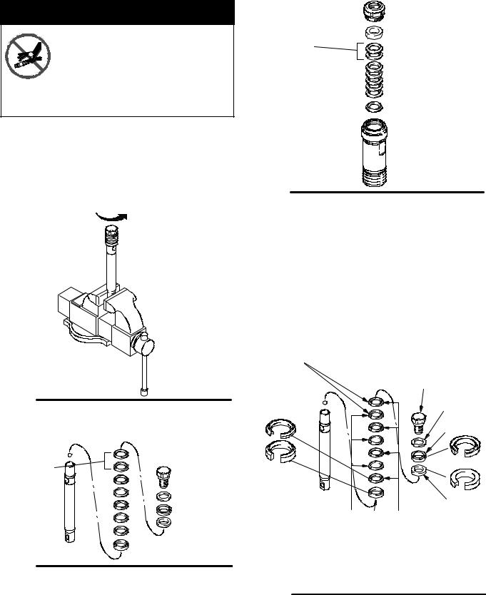
Disassembling the pump |
|
Fig. 3. Disassemble intake valve. Clean and inspect. |
Fig. 1. Remove packing nut (202) and throat adjust- |
O-ring (227) may require a pick for removal. |
|
|
||
ment spacer (228). |
|
|
202 |
|
211 |
|
|
used on |
228 |
249122, |
|
289590 |
||
|
||
|
227 |
ti6178b
Fig. 1
Fig. 2. Unscrew intake valve from cylinder.
7570e
Fig. 3
Fig. 4. Tap piston rod out of cylinder with a hammer or flip over and tap piston rod out against a bench.
Note: Sleeve may come out of cylinder with piston rod.
ti6180a
Fig. 4
Fig. 5. Remove piston rod from sleeve, or remove sleeve from cylinder.
ti6179a
Fig. 2
Fig. 5 |
ti6181a |
|
4 310894
Service
 WARNING
COMPONENT RUPTURE HAZARD
Do not clean or wipe the piston valve threads. Cleaning the piston valve
threads could destroy the special sealing patch and cause the piston valve to come loose during operation, causing pump bursting and possible serious bodily injury.
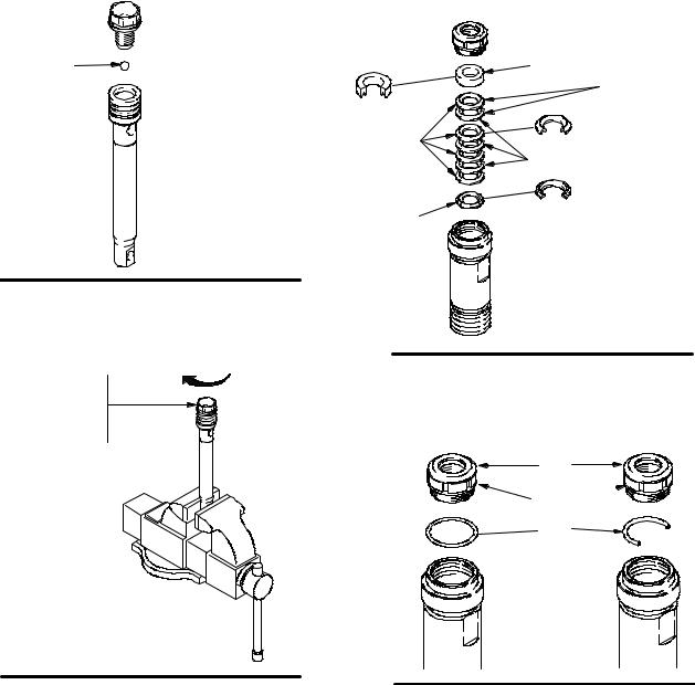
Fig. 6. Unscrew piston valve from piston rod. Clean and inspect parts. The piston has a special thread locking/sealing patch. Do not remove the patch. The patch allows four disassembly/assembly procedures before it is necessary to apply Loctiter to the threads.
ti6183a
Fig. 6
Fig. 7. Remove packings and glands from piston rod.
Not used on 287512
ti6184a
Fig. 7
Fig. 8. Remove throat packings and glands from cylinder. Discard throat packings and glands.
Not used on 287512
ti6182a
Fig. 8
Assembling the pump
Fig. 9. Soak all leather packings in SAE 30W oil for 1 hour minimum prior to assembly. Stack male gland (204) on piston rod. Alternately stack UHMWPE (208) and leather (218) packings (note orientation) on piston rod. Install female gland (217). Install piston wiper (216) (note orientation) and backup washer (229) on piston valve (210). The special sealing patch on piston valve threads is good for four repackings. Use Loctiter on piston valve threads after four repackings.
Not used on
287512
210
229
216
ti6185a |
218 |
204 |
208 |
217 |
|
|
Note: pump 249122 and 289590 do not use leather packings in piston stack. Alternately stack blue (208) and brown (218) packings on this pump.
Fig. 9
310894 5
Service
Fig. 10. Install ball (206) in piston rod. If Loctiter is applied to piston valve threads, ensure that none gets on ball.
Fig. 12. Soak all leather packings in SAE 30W oil for 1 hour minimum prior to assembly. Place male gland (204) in cylinder. Alternately stack UHMWPE (203) and leather packings (223) (note orientation). Place female gland (224) in top of cylinder. Seat packings.
206
ti6186a
Fig. 10
Fig. 11. Tighten piston valve to piston rod as specified:
Torque to 27 +/--3 ft-lb (36.61 +/-- 4.06 N• m)
(287512)
Torque to 55 +/--3 ft-lb (74.57 +/-- 4.06 N• m)
(249122, 287513, 289590)
ti6187a
Fig. 11
224 |
Not |
|
used on |
|
287512 |
223 |
|
203 |
|
204 |
|
ti6188a
Fig. 12
Fig. 13. Install seal (201) into packing nut (202). Install throat adjustment spacer (228) onto packing nut. Loosely install packing nut into cylinder.
201
202 
(228 o--ring
on 249122,  228 289590 )
ti6189a
Fig. 13
6 310894
 Loading...