


Gaggenau RC462704, RC472704, RC492704, RF411704, RF461704 Additional Planning Notes
...
Additional planning notes for Vario 400 series cooling
The side walls of the adjacent cabinetry have to be dimensionally stable, as the Vario cooling appliances are secured in the cutout with only an anti-tilt bracket on the top back and on the bottom at the side.
Vario cooling appliances can be installed handle to handle as a side-by-side combination. In this case the side-by-side installation kit RA 460 000 is required. If the distance between the appliances is greater than ⅝" (16 mm) or less than 6 ⁄ " (160 mm) or the environment very humid the additional side heating element RA 460 012 needs to be installed between the appliances to avoid condensation.
If the appliances are combined hinge to handle in a very humid environment the additional side heating element RA 460 012 is required as well. It can be omitted if the distance between the appliances is greater than 6 ⁄ " (160 mm) The additional side heating element RA 460 012 does not take up any additional space. It is already included in the cutout dimensions.
If the Vario cooling appliances are joined together hinge to hinge an additional stable side wall must be added.
If restrictions in use are accepted (no simultaneous opening of the doors possible) the appliances can be joined together directly, using the additional side heating element RA 460 012.
When installing a 400 series Vario cooling appliance next to a 400 series
BO/BM/BS/CM appliance, a minimum lateral distance of 1 ³⁄ " (30 mm) is required. Please see pages 13 and 15 for more information.
When installing a cooling appliance next to a BOP/BMP/BSP from the 200 series ovens, a minimum lateral distance of 1 ³⁄ " (30 mm) is required, if the non-hinge side of the cooling appliance is next to the BOP/BMP/BSP. If both appliances are hinged on the same side, a minimum lateral distance of 1 ⁄ " (40 mm) is required.
Door opening angle
To ensure correct kitchen planning it is essential to take into account the opening angle of the appliance door (plus fitted cabinet door and handle). There should be no possibility of collision with other kitchen furnishings (countertops, handles of other cabinetry etc.) or parts of the room (walls, protrusions etc.).
The space needed for the hinge and the consequential distance to the adjacent cabinetry and its handle can, depending on the panel thickness, be seen in the following drawing. The drawing assumes a panel thickness of ¾" (19 mm).
If a collision occurs, the following options are available to remedy the situation:
Restrict the door opening angle to 90° (standard 115°). Pin to restrict the angle is enclosed with the appliance. Due to limitation in use, it is not recommended to install a freezer (RF 411, RF 461, RF 463, RF 471, RF 491) next to a wall which requires
a door angle of 90°. If the restrictions in use are accepted, the ice storage container must be exchanged for the small ice storage container (RA 448 220). This must be done prior fixing the door. Fit a spacer between the appliance and the cabinetry that it would collide with. Rearrange surrounding cabinetry or appliance
Wall clearance RB 492/RY 492
Wall clearance RB 472/RC/RF/RW
C
|
|
|
|
|
|
|
E2 |
|
|
|
|
|
|
|
|
|
E1 |
|
|
D |
|
|
|
|
|
|
|
|
|
18" (457 mm) |
20 |
¹¹⁄ " (525 mm) |
9 ¼" |
(235 mm) |
10 |
⁄ " |
(265 mm) |
||
24" (610 mm) |
26 |
⅝" |
(677 mm) |
11 |
¾" |
(299 mm) |
13" |
(330 mm) |
|
30" (762 mm) |
32 |
¹¹⁄ " (830 mm) |
14 |
⁄ " |
(363 mm) |
15 |
⁄ " |
(395 mm) |
|
36" (914 mm) |
38 |
⁄ " |
(980 mm) |
16 |
⅞" |
(428 mm) |
18 |
⅛" |
(460 mm) |
|
|
|
|
|
Notes: |
|
|
|
|
|
|
|
|
|
|
|
|
|
|
|
|
|
|
|
|
|
|
|
|
|
|
|
|
|
– The adjustable feet have an adjustment range of +1 ⅜"(+35 mm) to -½-(13 mm). |
|
|
|
|
|
The standard height displayed in the pictures is 0 mm. |
|
|
|
|
|
– For proper ventilation of the appliance, the clearance between the floor and |
|
|
|
|
|
|
|
|
|
|
|
bottom edge of the cabinet front must be at least 3 ¹ ⁄ "(100 mm). |
|
|
|
|
|
– The panel thickness of customized doors can range from between ¾" (19 mm) |
¾" (19 mm). |
and 1 ½" (38 mm) (in the picture ¾" (19 mm)). |
||||
|
|
|
|
|
www.gaggenau.com/us |
|
|
|
|
|
Revised: 30 July 2020 |
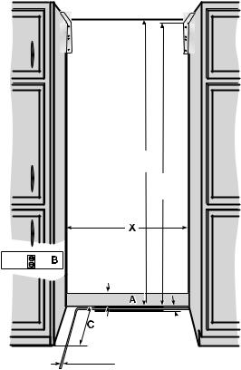
Installation cutout
Unlike conventional built-in appliances, cooling appliances stand on the floor. This means that the installation cutout is a space in a line of kitchen units.
Installation cutout
The specified dimensions of the installation cutout must be observed to guarantee the proper installation of the appliance and the design of the cabinet front.
It is particularly important that the installation cutout is square. The side walls must be smooth, not have any protrusions or unevenness. Use the appropriate tools, e.g. spirit level, diagonal measurements, etc. to determine whether the installation cutout is square.
The side walls and the upper molding of the installation cutout must be at least ⅝" (16 mm) thick.
Installation cutout for an individual appliance:
84"
(2134)
8311/16"
(2126)
315/16" (100)
1" (25)


 3/8" (10)
AArea for installation the water connection
BArea for installation the electrical connection must be outside the cutout
CDepth of installation cutout, depending on kitchen design.
C = 24" (610 mm) minimum!
X Width of installation cutout, refer to the table below for more details:
Appliance type |
Width of the cutout X |
17 ¾" (451 mm) |
18" (457 mm) |
|
|
23 ¾" (603 mm) |
24" (610 mm) |
|
|
29 ¾" (756 mm) |
30" (762 mm) |
35 ¾" (908 mm) |
36" (914 mm) |
Installation cutout for a side-by-side solution:
In a side-by-side solution, there are many ways to combine the appliances.
The width of the installation cutout is calculated from the sum of the widths of the individual appliances. The height and depth of the installation cutout correspond to the specifications for the individual appliances. It is important to comply with the dimensions in the area set aside for electric and water connections. For the precise dimensions, please refer to the details given for individual appliances.
Location
The appliance should be installed in a dry, well ventilated room. The location of the appliance should not be subject to direct sunlight or near a source of heat, such as an oven, a radiator, etc.
If installation next to a heat source is unavoidable, observe the following minimum distances from the heat source:
–1 ³⁄ " (3 cm) to electric or gas. When installing next to a cooktop, always refer to the cooktop installation instructions for more information.
–11 ¹³⁄ " (30 cm) from an oil or solid fuel cooktop.
The floor of the installation location must not give way; if required, reinforce floor. To ensure that the ice maker functions correctly, the appliance must be upright.
Surface
To ensure that the appliance is installed securely and functions properly, the surface must be level and even.
The floor must consist of a hard, rigid material.
The floor in the installation area must have the same height as the floor in the rest of the room.
Due to the heavy weight of a fully loaded appliance, the floor beneath must be stable. If in doubt, consult an architect, structural engineer or construction expert.
Refer to the following table for load-bearing capacity:
Model |
Description |
Maximum load weight |
RC462704 |
24" refrigeration column |
983 lbs (446kg) |
RC472704 |
30" refrigeration column |
1,148 lbs (521kg) |
RC492704 |
36" refrigeration column |
1,430 lbs (649kg) |
RF411704 |
18" freezer column |
806 lbs ( 366kg) |
RF461704 |
24" freezer column |
902 lbs (450kg)* |
RF471704 |
30" freezer column |
1,177 lbs (533kg) |
RF491704 |
36" freezer column |
1,403 lbs (636kg) |
RF463704 |
24" ice & water dispenser columns |
1,068 lbs (484kg) |
RF463705 |
||
RB472704 |
30" two-door bottom freezer |
1,222 lbs (554kg) |
|
|
|
RB492704 |
36" two-door bottom freezer |
1,444 lbs (655kg) |
|
|
|
RY492704 |
36" three-door bottom freezer |
1,682 lbs (763kg) |
|
|
|
RW414764 18" wine climate cabinet |
867 lbs (394)kg |
|
|
|
|
RW466764 24" wine climate cabinet |
1,093 lbs (496kg) |
|
|
|
|
*without water dispenser |
|
|
Neighboring cabinetry
The new appliance is screwed firmly in place with the neighboring cabinet parts. Care should be taken to ensure that all cupboards onto which something is fastened, are connected firmly to the floor or the wall.
The thickness of the toe kick can be a maximum ¾" (19 mm).
www.gaggenau.com/us
Revised: 30 July 2020
Planning Information
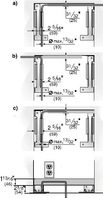
Water Location
A cold water connection is required for appliances that feature an ice maker or an ice and water dispenser.
The water pressure must be between 40 and 120 p.s.i. (2.75-8.25 bar). The installation must comply with local plumbing regulations.
A separate shut-off valve must be installed for the appliance water connection.
The shut-off valve for the water connection may not be behind the appliance. It is recommended to place the shut-off valve outside the cutout next to the appliance or in another easily accessible location. When installing the water connection, observe the permitted installation areas for the water supply line. The supply line can be located to the right (a), to the left (b), or underneath (c).
www.gaggenau.com/us
Revised: 30 July 2020
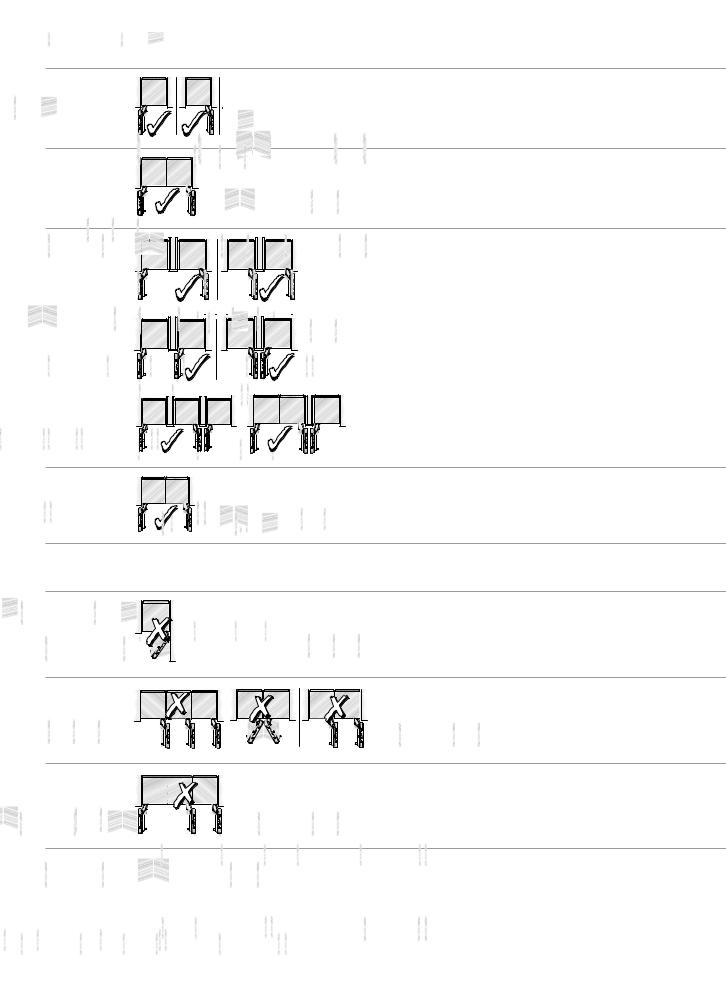
Installation options
The modular refrigerator and freezer column concept from Gaggenau offers you a variety of installation possibilities. In some instances, optional accessories are required!
Recommended Installations |
Considerations |
Stand-Alone |
Any appliance can be installed as a stand-alone unit. Ensure a cutout flush to |
|
the appliance at a depth of minimum 4" (102 mm), preferably 6" (152 mm) on |
|
the top and sides. |
Side-By-Side |
When two appliances are installed side-by-side a sealing kit must be |
|
used. For combinations that involve a freezer column, this kit is provided. For |
|
all other (non-traditional) side-by-side combinations or instances where any |
|
appliances are installed less than 6" (152 mm) apart from one another but not |
|
connected side-by-side, purchase the Heater Kit (RA 460 012). |
Split |
When dimensioning the partition, note the thickness of the door panel |
Columns |
(including handles) as well as the swivel range to prevent damage if the doors |
with |
are opened at the same time. (See page 242 for details on door opening |
Partition |
range dimensions) |
|
Three appliances can be installed together only if a partition—minimum 5/8" |
|
(16 mm)—is placed between two of the appliances. Ensure that door panel |
|
thickness (including handles) as well as the swivel range are accounted for. |
At The |
All Gaggenau cooling appliances must be completely enclosed on the top and |
End of a |
sides. If one side of the appliance is visible, a decorative side panel must be |
Cabinetry Run |
used. The side panel must be connected firmly to the wall, the floor and any |
|
overhead cabinet / fixtures before the appliance is placed in the cutout. |
Recommended Installations |
Concerns |
|
It is absolutely essential to ensure that the appliance is installed in such a way |
|
that the doors do not interfere with an adjacent wall or other kitchen |
|
elements. (See page 242 for details on door opening range dimensions) |
|
A partition—minimum 5/8" (16 mm)—is required to ensure the doors do not |
|
interfere with one another when opened. Use a partition to separate |
|
appliances and observe the door opening range. (See page 242 for details |
|
on door swivel range dimensions) |
|
A Gaggenau Three-door Bottom Freezer cannot be connected side-by-side |
|
with any other appliance. Use a partition to separate appliances and observe |
|
the door opening range. (See page 242 for details on door swivel range |
|
dimensions) |
*The Gaggenau warranty shall apply only to recommended installations.
www.gaggenau.com/us
Revised: 30 July 2020
 Loading...