


 Loading...
Gaggenau
INSTALLATION INSTRUCTIONS
INSTRUCTIONS D'INSTALLATION
INSTRUCCIONES DE INSTALACIÓN
VG 232 CA
Gas cooktop
Table de cuisson gaz
Encimera a gas
, IMPORTANT SAFETY INSTRUCTIONS
READ AND SAVE THESE INSTRUCTIONS
! " "
" #
$#
% & &' !' ( )'* +,-..+
/! /! /! " /
" 0 (
0
/
# "
"$1 #
2
, IMPORTANT SAFETY INSTRUCTIONS
READ AND SAVE THESE INSTRUCTIONS
INSTALLER: LEAVE THESE INSTRUCTIONS WITH THE APPLIANCE AFTER INSTALLATION IS COMPLETE. IMPORTANT: SAVE FOR THE LOCAL INSPECTOR’S USE.
,WARNING: Do not repair, replace or remove any part of the appliance unless specifically recommended in the manuals. Improper installation, service or maintenance can cause injury or property damage. Refer to this manual for guidance. All other servicing should be done by a qualified technician.
Appliance Handling Safety
Hidden surfaces may have sharp edges. Use caution when reaching behind or under appliance.
Safety Codes and Standards
This appliance complies with one or more of the following Standards:
UL 858, The Standard for the Safety of Household Electric Ranges
UL 923, The Standard for the Safety of Microwave Cooking Appliances
UL 507, The Standard for the Safety of Electric Fans
ANSI Z21.1, The American National Standard for Household Cooking Gas Appliances
CAN/CSA-C22.2 No. 113-M1984 Fans and Ventilators
CAN/CSA-C22.2 No. 61-M89 Household Cooking Ranges
It is the responsibility of the owner and the installer to determine if additional requirements and/or standards apply to specific installations.
Installation must conform with local codes or, in the absence of local codes, with the National Fuel Gas Code, ANSI Z223.1.
The appliance must be electrically grounded in accordance with local codes or, in the absence of local codes, with the National Electrical Code ANSI/ NFPA 70, latest edition. (In Canada, installation must be in accordance with the CAN 1-B149.1 and .2 Installation Codes for Gas Burning Appliances and/ or local codes.)
Electric Safety
For appliances equipped with a cord and plug, do not cut or remove the ground prong. It must be plugged into a matching grounding type receptacle to avoid electrical shock. If there is any doubt as to whether the wall receptacle is properly grounded, the customer should have it checked by a qualified electrician.
If required by the National Electrical Code (or Canadian Electrical Code), this appliance must be installed on a separate branch circuit.
Installer – show the owner the location of the circuit breaker or fuse. Mark it for easy reference.
Before installing, turn power OFF at the service panel. Lock service panel to prevent power from being turned ON accidentally.
Be sure your appliance is properly installed and grounded by a qualified technician. Installation, electrical connections and grounding must comply with all applicable codes.
Gas Safety
Install a gas shutoff valve near the appliance. It must be easily accessible in an emergency.
Leak testing must be conducted by the installer according to the instructions in this manual.
The appliance and its individual shutoff valve must be disconnected from the gas supply piping system during any pressure testing at pressures in excess of ½ psi (3.5 kPa).
The appliance must be isolated from the gas supply piping system by closing its individual manual shutoff valve during any pressure testing of the gas supply piping system at test pressures equal to or less than ½ psi (3.5 kPa).
The minimum supply pressure must be 1" water column above the manifold pressure printed on the data plate.
The maximum supply pressure must not exceed 14.0 inches water column (34.9 Millibars).
3
, IMPORTANT SAFETY INSTRUCTIONS
READ AND SAVE THESE INSTRUCTIONS
Propane Gas Installation
The propane gas tank must be equipped with its own high pressure regulator. In addition, the regulator supplied with this unit must also be used.
The appliance is shipped from the factory for use with natural gas. It must be converted for use with propane. A qualified technician or installer must do the conversion.
This appliance has been CSA certified for safe operation up to a height of 10,000 ft without any modifications. Exception: For use with propane the appliance must be converted per the LP conversion instructions.
For Massachusetts installations:
Installation must be performed by a qualified or licensed contractor, plumber or gas fitter qualified or licensed by the state, province or region where this appliance is being installed.
Shut-off valve must be a “T” handle gas cock.
Flexible gas connector must not be longer than 36 inches.
Installer - show the owner where the gas shut-off valve is located.
Related Equipment Safety
The appliance is only guaranteed safe to use if installed by a specialist in accordance with these installation instructions. The installer is liable for any damage resulting from incorrect installation.
Remove all tape and packaging before using the appliance. Destroy the packaging after unpacking the appliance. Never allow children to play with packaging material.
Never modify or alter the construction of the appliance. For example, do not remove leveling legs, panels, wire covers or anti-tip brackets/screws.
To eliminate the risk of burns or fire by reaching over heated surface units, cabinet storage space located above the surface units should be avoided. If cabinet storage is to be provided, the risk can be reduced by installing a hood that projects horizontally a minimum of 5 inches (127 mm) beyond the bottom of the cabinet.
Verify that cabinets above the cooktop are a maximum of 13" (330 mm) deep.
When installing a cooktop over a single oven, be sure to follow both the oven’s and cooktop’s installation manuals.
4

Before You Begin
Tools and Parts Needed
Phillips Head Screwdriver
Pencil
Drill with ¼" (6 mm) bit
Jigsaw
Tape Measure
Note: Additional materials may be necessary for installation in solid surface countertops. Contact the countertop manufacturer.
Parts Included
The minimum spaces that must be maintained when installing the gas cooktop shall be:
Aminimum 6" (150 mm)
Bminimum 6" (150 mm)
Cminimum 30" (762 mm) clearance between the top of the cooking surface and the bottom of the ventilation hood
Dminimum 19/16" (40 mm)
Eminimum 24" (600 mm)
Fminimum 18" (460 mm)
The distance from the top of the cooktop to the bottom of cabinets above can be reduced to 24" when the bottom of the wood or metal cabinet is protected by not less than ¼" (6.35 mm)-thick flame-retardant millboard covered with not less than No. 28 MSG sheet metal, 0.015 inch (0.4 mm) stainless steel, 0.024 inch (0.6 mm) aluminium or copper.
Cabinet Requirements
- |
3 |
( |
|
||
|
|
|
|
|
2 |
! |
|
|
|
|
|
5

Countertop Requirements
,WARNING: To reduce the risk of ignition of surrounding combustible materials, install at least 6" (150 mm) from both sidewalls and at least 2" (50 mm) from the rear wall.
The countertop must be level and horizontal. The stability of the countertop must be maintained after the cut-out has been made.
|
|
9:;4< |
|
|
=> ? |
|
|
4 |
|
8 |
|
8 |
|
567 |
|
|
9:;@< |
|
|
=A ? |
|
:65;:>< |
|
|
=B>@ ? |
>< =:C6 ? |
|
|
|
|
|
:5;:>< |
|
|
= 46 ? |
|
|
B< =C6 ? |
:5C;:>< =456 ?
B< =C6 ?
B4< =>66 ?
Technical Data
Total connected load electric: 0.8 VA
Gas |
Natural Gas |
LPG (Propane) |
|
Type N |
Type X |
|
|
|
Pressure |
6" water |
10" water |
|
column |
column |
|
(1.5 kPa) |
(2.5 kPa) |
|
|
|
A-burner full burn |
94 |
74 |
|
|
|
A-burner low burn |
49 |
36 |
|
|
|
B-burner full burn |
128 |
87 |
|
|
|
B-burner low burn |
58 |
42 |
|
|
|
Total connected load |
16 000 BTU |
16 000 BTU |
|
(4.7 kW) |
(4.7 kW) |
|
|
|
Total consumption |
0.45 m³/h |
340 g/h |
|
|
|
Installation Procedure
Prepare Installation Space
Create the cut-out in the countertop for one or several Vario appliances according to the installation diagram. The angle of of the cut surface to the countertop must be 90°.
After creating cut-out, remove shavings. Seal cut surfaces in a heat-resistant manner.
Some solid surface countertops require special installations. For example, heat reflective tape and rounded corners may be necessary. Contact the countertop manufacturer for instructions specific to your countertop.
Observe minimum distance between appliance underside and furniture parts of 3/8" (10 mm).
When installing multiple Vario appliances: Take into account space requirement for VV 200 connection strip between the appliances. Appliances can also be installed in individual cut-outs, bearing in mind a minimum distance between the appliances of 19/16" (40 mm).
Install Appliance
,WARNING: Before you plug in an electrical cord or turn on power supply, make sure all controls are in the OFF position.
1Make a mark exactly in the center of the cut-out. Fasten the mounting rails to the front and rear edge of the cut-out. The leading edges of the mounting rails must lie upon the countertop. The center marking of the mounting rails must correspond precisely with the center marking of the cut-out.
Note: For stone countertops, adhere the mounting rails with temperature-resistant dualcomponent adhesive (metal on stone).
6
2For combination with the VD 201 appliance cover: Mount appliance cover to appliance prior to installation (see VD 201 Installation Instructions).
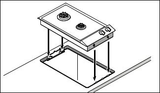
3Insert appliance in cut-out. The snap-in pins on the appliance must lie precisely on the clamp springs. Press appliance firmly into the cut-out.
The snap-in pins on the appliance must snap into the clamp springs.
Connect Gas Supply
The appliance is shipped from the factory for use with natural gas. It must be converted for use with propane. A qualified technician or installer must do the conversion.
Before connecting the appliance, please check whether the local connection conditions such as gas type and gas pressure match the appliance settings.
Make sure the gas supply is turned off at the manual shut-off valve before connecting the appliance.
The gas connection must be in a location that permits access to the manual shut-off valve and which, if applicable, is visible after opening the door of the cabinet.
SERVICER INFO ONLY
Connect the gas supply using the ½" U.S.A. elbow and the fiber gasket supplied with the unit. The shorter, nontapered thread fits into the threaded nut on the hob. The longer, tapered U.S.A. thread is for the incoming gas supply. Vent the gas line, check for leaks. The gas pressure regulator is supplied with the unit and comes set for natural gas. To convert regulator to LP (propane) gas:
Make-Essex Model SX 229 NA-602 ½ PSIG
1Remove the aluminum cap from the top of the regulator.
2Turn the cap over. It will have LP 10 stamped inside.
3Replace the cap on the regulator.
Make-Maxitrol Model RV 47 CL ½ PSIG
1Remove the aluminum cap from the top of the regulator.
2Remove the yellow plastic shaft from the cap by pushing it sideways until it pops out of the groove in the cap.
3Turn the shaft over and push back into the cutout in the cap.
4Replace the cap on the regulator.
Connect Electrical Supply
Before connecting supply cord to wall receptacle, make certain that gas shutoff valve and all burner controls are in OFF position.
Electrical connection (AC 110-127 V) is established by means of a connecting cord with a grounding contact plug connected to a grounded socket, which must also be accessible after installation of the gas cooktop.
Burner Cap Placement
The burner parts must be properly placed for the cooktop to function properly. If the burner parts are not properly placed, one or more of the following problems may occur:
Burner flames are too high.
Flames shoot out of burners.
Burners do not ignite.
Burner flames light unevenly.
Burner emits gas odor.
Placing Burner Parts
After electrical connection is complete, assemble the burner parts correctly and evenly. When assembling the burner parts, make sure that the burner head is placed on the base in such a way that the prongs of the burner cap fit snugly into the groove of the burner base.
7
Loading...