


9000655543 9000655543 920912
VA 420 000/ 001/ 010/ 011
Ø Montageanleitung
Ú Installation instructions Þ Notice de montage
â Istruzioni per il montaggio é Installatievoorschrift
Û Instrucciones de montaje ì Instruções de montagem
Ù Οδηγίες εγκατάστασης
ó Monteringsanvisning × Monteringsvejledning ê Monteringsveiledning Ý Asennusohje
î Инструкция по монтажу
Ö Montážní návod ë Instrukcja montażu ô Montaj kılavuzu
|
|
|
|
|
|
|
|
|


|
|
|
|
|
|
|
de
Verbindungsleiste
VA 420 000
Verbindungsleiste zur Kombination mit weiteren Vario Geräten der Serie 400 bei flächenbündigem Einbau
VA 420 001
Verbindungsleiste zur Kombination mit weiteren Vario Geräten der Serie 400 bei flächenbündigem Einbau mit Geräteabdeckung/Ausgleichsleiste
VA 420 010
Verbindungsleiste zur Kombination mit weiteren Vario Geräten der Serie 400 bei aufgesetztem Einbau
VA 420 011
Verbindungsleiste zur Kombination mit weiteren Vario Geräten der Serie 400 bei aufgesetztem Einbau mit Geräteabdeckung/ Ausgleichsleiste
Hinweise
■VK 414 und VF 414 aus Sicherheitsgründen nicht direkt nebeneinander einbauen.
■Montageanleitung der Geräte beachten.
■Reihenfolge beim Einbau der Geräte beachten (von rechts nach links, von links nach rechts):
Falls eine Fritteuse VF 414 oder ein Dampfgarer VK 414 am Rand einer Gerätereihe montiert wird, dann dieses Gerät als erstes montieren.
■VL 414 nur mit aufgesetzter Montagehilfe einbauen.
Einbau
1.Ausschnitt in der Arbeitsplatte herstellen.
2.Erstes Gerät in den Ausschnitt einsetzen.
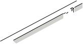
3.Die Verbindungsleiste zuerst hinten in den Ausschnitt einsetzen, dann das vordere Federelement eindrücken und die Verbindungsleiste in den Ausschnitt einsetzen (Bild 2).
Hinweis: Die abgeschrägte Kante der Verbindungsleiste muss nach hinten zeigen.
4.Verbindungsleiste fest an das Gerät schieben, die Klemmfedern des Gerätes müssen hörbar in den Aussparungen an der Verbindungsleiste einschnappen (Bild 3).
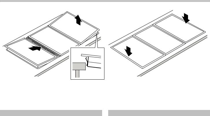
5.Weitere Geräte und Verbindungsleisten einsetzen (Bild 4).
6.Um die gesamte Gerätekombination sauber in den Ausschnitt einzusetzen, das letzte Gerät einlegen und die beiden äußeren Geräte jeweils an der Außenkante leicht nach oben heben (Federn entlasten – Bild 5). Dann gleichzeitig die beiden äußeren Geräte an den Außenkanten nach unten in den Ausschnitt drücken (Bild 6).
en
Connection strip
VA 420 000
Connection strip for combination with other Vario 400 appliances for flush installation
VA 420 001
Connection strip for combination with other Vario 400 appliances for flush installation with appliance cover/extension
VA 420 010
Connection strip for combination with other Vario 400 appliances for surface installation
VA 420 011
Connection strip for combination with other Vario 400 appliances for surface installation with appliance cover/ extension
Notes
■For safety reasons, do not install VK 414 and VF 414 directly next to each other.
■Observe the installation instructions of the appliances.
■Install the appliances in the correct order (from right to left, or from left to right):
If the deep fryer VF 414 or the steamer VK 414 is to be installed as the first or the last appliance in the combination, then install this appliance as the first one.
■Only install the downdraft ventilation VL 414 with the mounting device fitted.
Installation
1.Produce the cut-out in the worktop.
2.Insert the appliance into the cut-out
3.Join the connecting strip at the rear first, then push in the spring element on the front and insert the connecting strip in the cut-out (Fig. 2).
Note: the rouded edge of the connecting strip has to point to the rear.
4.Firmly push the connecting strip against the appliance, the spring clips on the side of the appliance must snap into the recesses of the connecting strip (Fig. 3).
5.Insert further appliances and connecting strips (Fig. 4).
6.In order to facilitate a perfect assembly of the complete range in the cut-out, insert the last appliance and slightly tilt the two appliances on either end of the range slightly upwards on the outer edge (to relieve the spring clips – Fig. 5). Then simultaneously push both appliances into the recess on the outer edge (Fig. 6).
 Loading...