


 Loading...
Gaggenau |
|
Installation instructions .......................... |
2 |
Notice de montage ............................... |
17 |
Instrucciones de instalación ................ |
34 |
VL 414 111 / AA 490 711
Downdraft ventilation
Aérateur de plan de cuisson
Extractor de superficie
9 Safety Definitions
9WARNING
This indicates that death or serious injuries may occur as a result of non-observance of this warning.
9CAUTION
This indicates that minor or moderate injuries may occur as a result of non-observance of this warning.
NOTICE: This indicates that damage to the appliance or property may occur as a result of non-compliance with this advisory.
Note: This alerts you to important information and/or tips.
2

9 IMPORTANT SAFETY INSTRUCTIONS
READ AND SAVE THESE INSTRUCTIONS
INSTALLER: LEAVE THESE INSTRUCTIONS WITH THE APPLIANCE AFTER INSTALLATION IS COMPLETE.
IMPORTANT: SAVE THESE INSTRUCTIONS FOR THE LOCAL ELECTRICAL INSPECTOR'S USE.
WARNING
If the information in this manual is not followed exactly, fire or shock may result causing property damage or personal injury.
WARNING
Do not repair, replace or remove any part of the appliance unless specifically recommended in the manuals. Improper installation, service or maintenance can cause injury or property damage. Refer to this manual for guidance. All other servicing should be done by an authorized servicer.
WARNING
WARNING – TO REDUCE THE RISK OF FIRE, ELECTRIC SHOCK, OR INJURY TO PERSONS, OBSERVE THE FOLLOWING:
‒Installation work and electrical wiring must be done by qualified person(s) in accordance with all applicable codes and standards, including firerated construction.
‒Sufficient air is needed for proper combustion and exhausting of gases through the flue (chimney) of fuel burning equipment to prevent back drafting. Follow the heating equipment manufacturer’s guideline and safety standards such as those published by the National Fire Protection Association (NFPA), and the American Society for Heating, Refrigeration and Air Conditioning Engineers (ASHRAE), and the local code authorities.
‒When cutting or drilling into wall or ceiling, do not damage electrical wiring and other hidden utilities.
‒Ducted fans must always be vented to the outdoors.
WARNING
The applicable regulations of the energy supply companies and the regional construction regulations must be observed when installing the hood.
WARNING
Risk of fire
Grease deposits in the grease filter can catch fire. Never work with a naked flame near the appliance (e.g. flambéing). Install the unit near a heat-producing appliance for solid fuels (e.g. wood or coal) only if there is a closed, non-detachable cover. There must be no flying sparks.
WARNING
Risk of fire
Operating several gas burners at the same time gives rise to a great deal of heat. The ventilation appliance may become damaged or catch fire. The ventilation appliance must only be combined with gas burners that do not exceed the maximum total output of 61,000 BTU/ hr (18 kW). If 41,000 BTU/hr (12 kW) is exceeded, the local regulations concerning room ventilation, room size, and combination with ventilation devices in exhaust and recirculating operation must be followed.
WARNING
To reduce risk of fire and to properly exhaust air, be sure to duct air outside. Do not vent exhaust air into spaces within walls, ceilings, attics, crawl spaces or garages.
WARNING
To reduce the risk of fire, use only metal ductwork.
3

9 IMPORTANT SAFETY INSTRUCTIONS
READ AND SAVE THESE INSTRUCTIONS
WARNING
When the hood is operated in exhaust-air mode simultaneously with a different burner which also makes use of the same chimney (such as gas, oil or coal-fired heaters, continuous-flow heaters, hot-water boilers) care must be taken to ensure that there is an adequate supply of fresh air which will be needed by the burner for combustion.
Safe operation is possible provided that the under pressure in the room where the burner is installed does not exceed 4 Pa (0.04 mbar).
This can be achieved if combustion air can flow through non-lockable openings, e.g. in doors, windows and via the air-intake/exhaust-air wall box or by other technical measures, such as reciprocal interlocking, etc.
WARNING
Avoid carbon monoxide poisoning – Provide adequate air intake so combustion gases are not drawn back into the room.
An air-intake/exhaust-air wall box by itself is no guarantee that the limiting value will not be exceeded.
Note: When assessing the overall requirement, the combined ventilation system for the entire household must be taken into consideration. This rule does not apply to the use of cooking appliances, such as cooktops and ovens.
CAUTION
For general ventilating use only. Do not use to exhaust hazardous or explosive materials and vapors.
Appliance Handling Safety
Unit is heavy and requires at least two people or proper equipment to move.
Hidden surfaces may have sharp edges. Use caution when reaching behind or under appliance.
WARNING
Risk of injury
The appliance may fall from the wall if it is not attached properly. All fastening components must be fixed firmly and securely in place.
WARNING
Risk of tipping over
The appliance is very narrow and can tip over easily. Do not place appliance upright on the floor. Place the appliance flat on the floor.
Safety Codes and Standards
This appliance complies with the latest version of one or more of the following standards:
UL 507 - Electric Fans
CAN/CSA C22.2 No. 113 - Fans and Ventilators
It is the responsibility of the installer to determine if additional requirements and/or standards apply to specific installations.
Electric Safety
WARNING
GROUNDING INSTRUCTIONS
This appliance must be grounded. In the event of an electrical short circuit, grounding reduces the risk of electric shock by providing an escape wire for the electric current.
This appliance is equipped with a cord having a grounding wire with a grounding plug. The plug must be plugged into an outlet that is properly installed and grounded.
WARNING
Improper grounding can result in a risk of electric shock. Consult a qualified electrician if the grounding instructions are not completely understood, or if doubt exists as to whether the appliance is properly grounded. Do not use an extension cord. If the power supply cord is too short, have a qualified electrician install an outlet near the appliance.
4
9 IMPORTANT SAFETY INSTRUCTIONS
READ AND SAVE THESE INSTRUCTIONS
WARNING
Before you plug in an electrical cord or turn on power supply, make sure all controls are in the OFF position.
For appliances equipped with a cord and plug, do not cut or remove the ground prong. It must be plugged into a matching grounding type receptacle to avoid electrical shock. If there is any doubt as to whether the wall receptacle is properly grounded, the customer should have it checked by a qualified electrician.
If required by the National Electrical Code (or Canadian Electrical Code), this appliance must be installed on a separate branch circuit.
WARNING
To reduce the risk of fire or electric shock, do not use this fan with any solid-state speed control device.
Installer – show the owner the location of the circuit breaker or fuse. Mark it for easy reference.
Before installing, turn power OFF at the service panel. Lock service panel to prevent power from being turned ON accidentally.
WARNING
TO REDUCE THE RISK OF FIRE, ELECTRIC SHOCK, OR INJURY TO PERSONS, OBSERVE THE FOLLOWING:
‒Use this unit only in the manner intended by the manufacturer. If you have questions, contact the manufacturer.
‒Before servicing or cleaning unit, switch power off at service panel and lock the service disconnecting means to prevent power from being switched on accidentally.
When the service disconnecting means cannot be locked, securely fasten a prominent warning device, such as a tag, to the service panel.
Be sure your appliance is properly installed and grounded by a qualified technician. Installation, electrical connections and grounding must comply with all applicable codes.
WARNING
Risk of electric shock
Parts inside the appliance can have sharp edges. The connection cable can be damaged. Do not bend or pinch connection cables during installation.
Related Equipment Safety
Remove all tape and packaging before using the appliance. Destroy the packaging after unpacking the appliance. Never allow children to play with packaging material.
The appliance should only be used if installed by a qualified technician in accordance with these installation instructions. The manufacturer is not responsible for any damage resulting from incorrect installation.
Never modify or alter the construction of the appliance. For example, do not remove leveling legs, panels, wire covers or anti-tip brackets/screws.
Proposition 65 Warning:
This product may contain a chemical known to the State of California, which can cause cancer or reproductive harm. Therefore, the packaging of your product may bear the following label as required by California:
67$7( 2) &$/,)251,$ 352326,7,21 :$51,1*
:$51,1*
&DQFHU DQG 5HSURGXFWLYH +DUP ZZZ3 :DUQLQJV FD JRY
5

General Notes
Exhaust air mode
Note: Ventilation may not exit through an already operational smoke or exhaust chimney, nor a duct used for ventilating furnace installation areas.
If the ventilation is intended to pass through a smoke or exhaust chimney that is not in operation, the responsible area heating inspector must give approval.
If the ventilation passes through an external wall, use a telescope wall sleeve.
Ventilation line
Note: The appliance manufacturer does not assume any warranty for complaints attributable to the duct section.
The appliance achieves its optimum performance by means of a short, straight exhaust air duct and as large a duct diameter as possible.
As a result of long rough exhaust air ducts, many duct bends or duct diameters that are smaller than 6" (150 mm), the optimum extraction performance is not achieved and fan noise is increased.
The ducts or hoses for laying the exhaust air line must be made of non-combustible material.
Use sealing strip for deviating duct diameters.
Electrical connection
9WARNING
Risk of electric shock
Parts inside the appliance can have sharp edges. The connection cable can be damaged. Do not bend or pinch connection cables during installation.
Check your domestic installation before installing the appliance. Pay attention to suitable fusing of your domestic installation. The voltage and frequency of the appliance must agree with the electrical installation (see rating plate).
The appliance complies with protective class I and may only be operated with a PE conductor connection.
The installation must contain a disconnector with a contact opening of at least X” (3 mm) that isolates all poles from the mains. It must still be accessible after installation.
Only an electrical specialist may lay or replace the connecting lead, paying attention to the applicable regulations.
If the mains connecting lead of this appliance is damaged, it must be replaced with a special connecting lead, which is obtainable from the manufacturer or the manufacturer's after-sales service.
6

Before you begin
Tools and parts needed
Screwdriver Torx T20
Pencil
Drill with ¼" (6 mm) bit
Jigsaw
Tape Measure
Note: Additional materials may be necessary for installation in solid surface countertops. Contact the countertop manufacturer.
Parts included
Installation accessories
VA 420 000 Connection strip for combination with other Vario appliances in the 400 series for flush installation
VA 420 001 Connection strip for combination with other Vario appliances in the 400 series for flush installation with appliance cover/compensation strip
VA 420 010 Connection strip for combination with other Vario appliances in the 400 series for surface-mounted installation
VA 420 011 Connection strip for combination with other Vario appliances in the 400 series for surface-mounted installation with appliance cover/ compensation strip
VA 450 110 11 cm compensation strip for depth compensation when using several Vario appliances
AD 724 040 Connection piece for round duct DN 125 mm
For side connection to VL, additional adapter plate AD 724 041 is required
AD 724 041 Adapter plate for side connection from AD 724 040 to VL
AS 070 001 Connection piece for extending when installing beside VK or VF
Installation schematic
9/ 

 $$
$$
$5
7
Appliance dimensions
To achieve optimum extraction performance, the maximum width of one single cooktop between two ventilation elements should be 23 5/8” (60 cm).
â âPP |
|
|
PLQ ç¼ʚ â |
|
|
PLQ â |
|
|
ʌ¼ʓʘ â |
ç¼ʚ â |
|
â |
ê â |
|
|
|
|
èç¼ʓʘ |
¡ |
|
|
|
|
|
|
|
|
|
|
|
â |
ʌ¼ʓʘ â |
|
|
|
ê â |
|
|
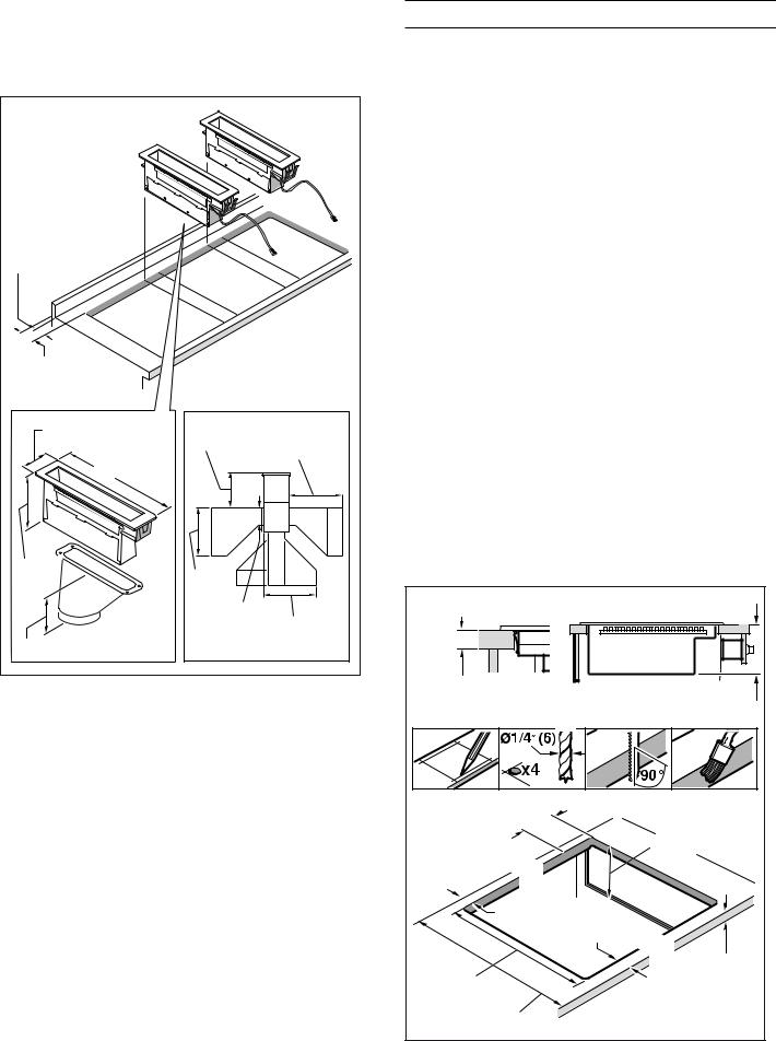
Prepare Installation Space
The kitchen unit must be heat-resistant to at least 200° F (90°C). The stability of the unit must be maintained after producing the cut-out.
Produce the cut-out in the countertop for one or more Vario appliances as shown in the installation sketch. The angle between the cut surface and the countertop must be 90°.
The cut edges at the sides must be flat to ensure a good fit of the retaining springs on the appliance. In laminated worktops, it may be necessary to fit strips at the sides of the cut-out.
Remove shavings after cutting. Seal cut surfaces for resistance to heat and so they are watertight.
Pay attention to a minimum gap of 3/8“ (10 mm) from the underside of the appliance to kitchen units.
Use suitable base constructions to ensure load-carrying capacity and stability, especially in the case of thin countertops. Pay attention to the weight of the appliance, including any payload. Reinforcement material used must be resistant to heat and moisture.
Note: Wait until the appliance has been installed in the installation opening before checking that it is level.
Cutting out countertop
PLQ ë â |
ʌ¼ʚ â |
|
|
ʐ¼ʓʘ |
|
|
PLQ ʎ¼ʚ |
PLQ â |
|
PLQ â |
|
ç¼ʚ è¼ʓʘ |
PLQ ë â |
|
|
|
|
|
|
PLQ ʌ¼ʚ â |
PP |
8
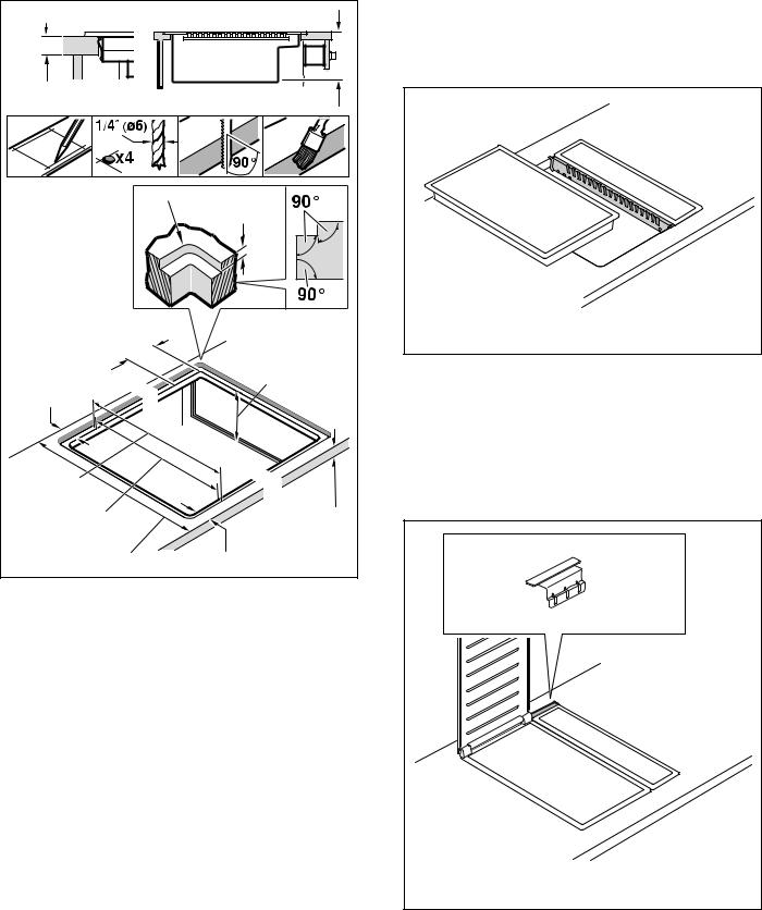
Flush mounting: Flush mounting into a countertop is possible.
PLQ ç¼ʓʘ |
|
|
|
|
ë â |
|
|
|
|
|
|
|
|
|
|
U ç¼ʓʘ |
â è¼ʕʔ |
|
|
|
|
|
|
|
|
||
|
|
|
|
|
è¼ʚ âè¼ʘʖ |
|
|
|
|
|
|
|
|
|
ʐ¼ʓʘ |
|
|
|
|
|
|
|
|
|
|
PLQ ʎ¼ʚ |
|
PLQ â |
|
|
|
|
|
|
èè¼ʓʘ è¼ʓʘ |
|
|
|
|
|
|
|
|
|
|
|
|
|
|
|
|
|
|
|
|
ç¼ʚ |
è¼ʓʘ |
|
|
|
|
PLQ ë â |
|
|
|
|
|
|
|
PLQ ʌ¼ʚ â |
PLQ â |
PP |
||||
Flush installation: The appliance can be installed in the following temperatureand water-resistant countertops:
Stone countertops
Plastic countertops (such as Corian®)
Solid wood countertops: Only in consultation with the manufacturer of the countertop (seal cut-out edges)
Installation in other countertops only in consultation with the manufacturer of the countertop.
Installation in countertops made of particleboard is not possible.
Note: Any cut-out work on the countertop must be performed in a workshop according to the installation diagram. The cut-out must be made cleanly and precisely since the cut-out edge is visible on the surface. Clean and degrease the cut-out edges with a suitable cleaning agent (bear in mind silicone manufacturer's processing instructions).
Combining several Vario devices: The connecting strip VA 420 000/001/010/011 is required for the combination of several Vario appliances. This is available separately as a special accessory. Consider additional space requirement for the connecting strip between the appliances when making the cut-out (see installation instructions VA 420 000/001/010/011).
9$ |
Appliances can also be installed in individual cut-outs, bearing in mind a minimum distance between the devices of 2" (51 mm).
When combining several appliances with or without appliance cover, you can use the appliance extensions VA 450 110/-401/-600/-800/-900 (depending on appliance width) to balance out dimension differences.
9$ |
9
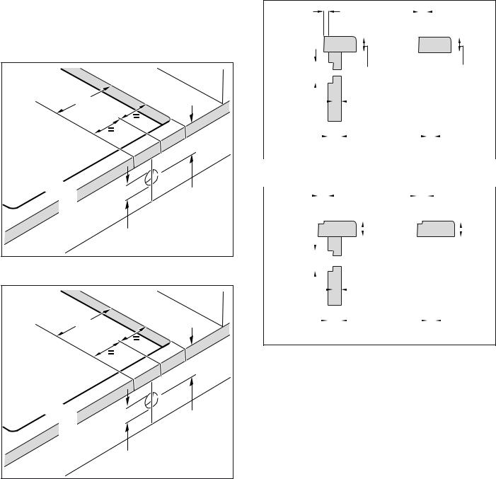
Hole for control knobs
The built-in control panel can be integrated in the bottom cupboard at drawer level. Panel thickness: 5/8" - 1" (16 - 26 mm)
1As shown in the figure, produce the Ø 1 3/8"
(35 mm) holes for fastening the control knobs in the front of the bottom cupboard. A drilling template is provided for exact positioning of the drill holes.
ʐ¼ʓʘ |
è¼ʚ |
ç¼ʚ |
ç¼ʚ |
For flush installation:
ʐ¼ʓʘ |
è¼ʚ |
ç¼ʚ |
ç¼ʚ |
2If the front panel is more than 1" (26 mm) thick: mill out the rear of the front panel so that it is no thicker than 1" (26 mm). Choose the dimensions of the milled recess according to the control panel.
PLQ ç¼ʓʘ |
|
|
|
|
PLQ ç¼ʓʘ |
||||
|
|
|
|
||||||
|
|
||||||||
|
|
|
|
|
|
|
|
|
|
|
|
|
|
|
|
|
|
|
|
|
|
|
|
|
|
|
|
|
|
|
|
|
|
|
|
|
|
|
|
|
|
|
|
|
ʌ¼ʓʘ [ è¼ʚ |
|
|
PLQ ë |
|
PLQ ë |
|||||||||
|
||||||||||||||
[ |
|
|
|
|
|
|
|
' |
|
|
|
|
|
|
|
|
|
|
|
|
|
|
|
|
|
|
|
||
|
|
|
|
|
|
|
|
|
|
|
|
|
||
|
|
|
|
|
|
|
|
|
|
|
||||
|
|
|
|
|
|
|
|
|
||||||
|
|
|
|
|
|
|
|
|
|
|
|
|
|
|
|
|
|
|
|
|
|
|
|
|
|
|
|
|
|
|
|
|
|
|
|
|
|
|
|
|
|
|
|
|
' ! |
|
|
|
|
ʌ¼ʚ PP |
||||||||||||||||||||||||
For flush installation: |
|
|
|
|
|
|
|
|
|
|
|
|
|||||||||||||||||
|
|
|
|
|
|
|
|
|
|
|
|
|
|
|
|
|
|
|
|
|
|
|
|
|
|
|
|||
|
|
|
|
|
|
|
|
PLQ ç¼ʓʘ |
|
|
|
|
|
|
|
PLQ ç¼ʓʘ |
|||||||||||||
|
|
|
|
|
|
|
|
|
|
|
|
|
|
|
|||||||||||||||
|
|
|
|
|
|
|
|
|
|
|
|
|
|
|
|
|
|
|
|
|
|
|
|
|
|
|
|
|
|
|
|
|
|
|
|
|
|
|
|
|
|
|
|
|
|
|
|
|
|
|
|
|
|
|
|
|
|
|
|
|
|
|
|
|
|
|
|
|
|
|
|
|
|
|
|
|
|
|
|
|
|
|
|
|
|
|
|
|
|
|
|
|
|
|
|
|
|
|
|
|
|
|
|
|
|
|
|
|
|
|
|
|
|
|
|
|
|
|
|
|
|
|
|
|
|
|
|
|
|
|
PLQ |
|
ç¼ʓʘ |
|
|
|
|
|
|
|
|
|
|
|
|
||||
|
|
|
|
|
|
|
|
|
|
|
|
|
|
|
|
|
|
|
|
|
|
|
|
||||||
|
|
|
|
|
|
|
|
|
|
|
|
|
|
|
|
|
|
|
|
|
|||||||||
ʌ¼ʓʘ [ |
è¼ʚ |
|
|
|
|
|
|
|
|
|
|
|
|
PLQ ç¼ʓʘ |
|||||||||||||||
|
|
|
|
|
|
|
|
|
|
|
|||||||||||||||||||
[ |
|
|
|
|
|
|
|
|
|
|
|
|
|||||||||||||||||
|
|
|
|
|
|
|
|
|
|
|
|
' |
|
|
|
|
|
|
|
|
|
|
|
|
|||||
|
|
|
|
|
|
|
|
|
|
|
|
|
|
|
|
|
|
|
|
|
|
|
|
||||||
|
|
|
|
|
|
|
|
|
|
|
|
|
|
|
|
|
|
|
|
|
|
|
|
||||||
|
|
|
|
|
|
|
|
|
|
|
|
|
|
|
|
|
|
|
|
|
|
|
|
||||||
|
|
|
|
|
|
|
|
|
|
|
|
|
|
|
|
|
|
|
|
|
|
|
|
|
|
|
|
|
|
|
|
|
|
|
|
|
|
|
|
|
|
|
|
|
|
|
|
|
|
|
|
|
|
|
|
|
|
|
|
|
|
|
|
|
|
|
|
|
|
|
|
|
|
|
|
|
|
|
|
|
|
|
|
|
|
|
|
|
|
' ! ʌ¼ʚ
PP
10
Installation Procedure
Installation of control console
Note: Only install the appliance in conjunction with the corresponding control console.
1Remove the packaging of the control knobs and the protective film from the light rings.
2Hold the bracket against the front panel from the rear. Insert the control knob in the holes from the front and screw it down it from the rear with the nut.
3Using the screws included, bolt down the control panel on the bracket.
9 |
CAUTION |
Appliance damage! Establish equipotential bonding. Before the control cables may be plugged onto the control panel, the stranded grounding wire from the control unit must be fitted on the control panel.
11
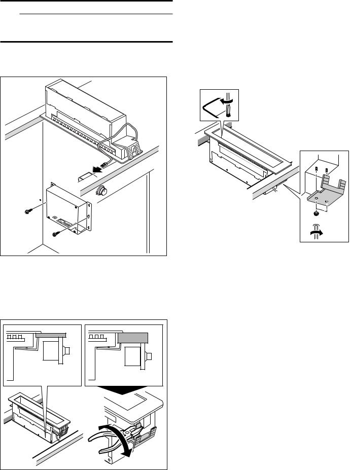
Install Appliance
9WARNING
Before you plug in an electrical cord or turn on power supply, make sure all controls are in the OFF position.
1Plug the control cable into the socket on the control desk. The plug must snap into place.
Insert and align the appliance in the cutout horizontally. Tighten the rear clamp using the screw inside the appliance. Tighten the front clamp from below.
Notes
‒Do not overtighten the clamps, ensure that there is a uniform seal gap on all sides.
‒The rear clamp pivots out on its own during tightening.
‒The appliance must not be bonded to the countertop with silicone.

 0
0
2Shorten the front clamp relative to the countertop thickness. Break the metal sheets off at the predetermined breaking points.
Note: Make sure that you do not shorten it too much, the clamping effect to the countertop must be guaranteed.
12 |

3Use the installation aid. Horizontally insert the downdraft ventilation unit in the recess and align it. Remove the sealing element. Insert the installation aid at an angle into the ventilation recess and align it vertically to the appliance. Position the appliance at an angle in front of the downdraft ventilation unit and press it into the recess via the installation aid. Remove the installation aid. Fasten the downdraft ventilation unit as described above.
Notes
‒You must use the included installation aid if the downdraft ventilation unit is in a combination with several Vario appliances in the last or last but one position.
‒The installation aid protects the appliance edges from damage.
4Fit the connection piece in the required position.
Notes
‒Depending on the installation situation, the exhaust air can be guided in three different directions.
‒Corresponding to the space conditions, the connection piece can be turned by 180°.
‒For details of exhaust air guidance, also refer to the instructions for the remote fan unit.
5Secure the exhaust air pipe to the connecting pieces and seal appropriately..
Note: If you use an aluminium pipe, smooth the connection area beforehand.
13 |
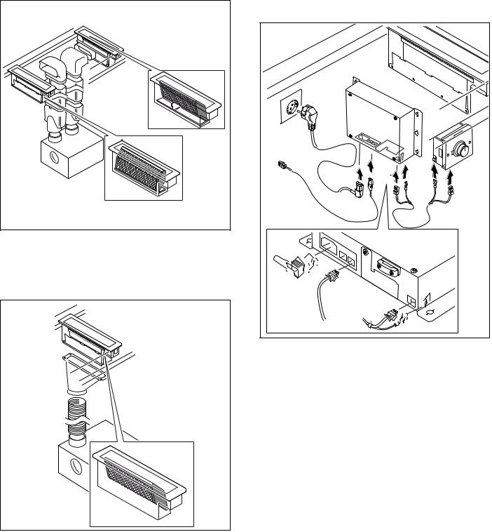
6Fit the grease filter:
The positioning plate is used to correctly position the grease filter near the side air outlet. Place the positioning plate in the ventilation element so that the central angle is facing the air outlet. Place the grease filter on the positioning plate.
For downwards air outlet, place the grease filter without the positioning plate in the ventilation element. The alignment of the grease filter does not matter.
7Plug the control cable of the control unit into the socket on the control desk. Connect the control unit and the fan module with the control cable. All plugs must snap into place. Connect the control unit and fan module to the mains and check that they work correctly. If the appliance does not work, check that the connection cable is positioned correctly.
8Flush installation only: it is imperative to test functioning before jointing! Joint the surrounding gap with a suitable, temperature-resistant silicone adhesive (such as OTTOSEAL® S 70). Smoothen the seal joint with smoothing agent recommended by the manufacturer. Observe the notes on processing the silicone adhesive. Do not operate the appliance until the silicone adhesive has dried completely (at least 24 hours, depending on room
temperature).
NOTICE: Unsuitable silicone adhesive used on natural stone worktops will cause permanent discoloration.
14

Connect Electrical Supply
9WARNING
Risk of electric shock
Parts inside the appliance can have sharp edges. The connection cable can be damaged. Do not bend or pinch connection cables during installation.
Refer to data plate for more information. See "Service" for data plate location.
The branch-circuit breakers ampacity, the wire sizes and the connections must conform to the requirements of the National Electrical Code or Canadian Electrical Code and all local codes and ordinances.
This appliance is connected with a plug
Plug has to be conform with NEMA CONFIGURATIONS FOR PLUGS AND RECEPTACLES.
The appliance must be properly grounded.
Plug must be rated not less than type 6-20 P (2-pole 3-wire grounding).
Only a qualified electrician should connect the plug.
Install a socket outlet earthed in accordance with regulations approx. 27" (700 mm) above the floor behind the appliance. The socket outlet must still be accessible after installation.
Ventilation molding
If downdraft ventilation is used next to a gas appliance, a ventilation molding AA 414 010 must be fitted on the gas appliance during cooking. The ventilation molding improves extraction when using gas appliances. The ventilation molding prevents extinction of small flames due to the draft.
AA 414 010 Ventilation molding, for operation next to the VG 414/415/424/425 gas appliance
Removing appliance
Disconnect the appliance from the power supply. For flush-mounted appliances, remove the silicone joint. Push out the appliance from below.
9CAUTION
Damage to appliance! Don't lever device out from above at the frame.
Connection for window contact switch AA 400 510
Work on the connection for the window contact switch must only be carried out by a qualified electrician in accordance with the requirements and standards of the country in which in the appliance is being used.
The appliance has a connection (X17) for a window contact switch. The window contact switch can be flush mounted or surface mounted. You will receive the window contact switch AA 400 510 separately as an accessory. Please observe the installation instructions enclosed with the window contact switch.
If a window contact switch is connected, the extractor hood's ventilation system will only work with the window open. The lighting will work even if the window is closed.
If you switch on the ventilation system with the window closed, the button for the ventilation setting you have selected will flash, and the ventilation system will not switch on.
If you close the window while the ventilation system is on, the appliance will switch the ventilation system off within 5 seconds. The button for the ventilation setting you have selected will flash.
The entire ventilation network and window contact switch must be assessed by a master chimney sweep.
15
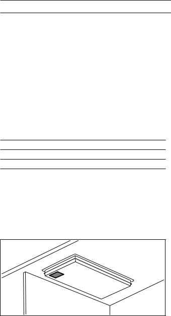
Customer Service
If your appliance needs repairs, our customer service is there for you. We work hard to help solve problems quickly and without unnecessary service calls, getting your appliance back up and running correctly in the least amount of time possible.
When you call, please indicate the product number (E-Nr.) and serial number (FD-Nr.) so that we can
support you in a qualified manner. You will find the type plate with these numbers on the bottom of the appliance. To avoid having to search for a long time when you need it, you can enter your appliance data and the customer support telephone number here.
E-Nr. FD-Nr.
Customer Service O
Please read the installation instructions and use and care instructions provided with your appliance. Failure to do so may result in an error in using the appliance. This could result in a service call that instead of fixing a mechanical issue is only needed for customer education. Such calls are not covered by the appliance warranty.
Please find the contact data of all countries in the enclosed customer service list.
To book a service visit and product advice
USA 877 442 4436 toll-free
CANADA 877 442 4436 toll-free
16
Loading...