


 Loading...
Gaggenau
Instruction manual Instrucciones de uso Instruções de serviço
Οδηγíες χρήσεω
VL 414/AA 490
Downdraft ventilation Extractor de superficie
Elemento de ventilação de bancada
Εξαεριστήρας βάσης εστιών

Table of contents |
3 |
|
|
Índice |
13 |
|
|
Índice |
23 |
|
|
Πίνακας περιεχομένων |
32 |
|
|
2

Table of contents
Important safety information |
4 |
|
|
Environmental protection |
6 |
Environmental protection |
6 |
|
|
Operating modes |
6 |
|
|
Exhaust air mode |
6 |
Air recirculation |
6 |
|
|
Your new appliance |
7 |
Downdraft ventilation |
7 |
Control knob |
7 |
Visual signals of the luminous disc |
7 |
Special accessories |
8 |
Installation accessories |
8 |
|
|
Operation |
8 |
|
|
Before using for the first time |
8 |
Switching on |
8 |
Switching off |
8 |
Run-on function |
9 |
Locking mechanism |
9 |
Ventilation moulding |
9 |
|
|
Cleaning |
10 |
Cleaning the appliance |
10 |
Cleaning the metal mesh grease filters |
10 |
Removing and refitting the metal grease filter |
11 |
|
|
Trouble shooting |
12 |
|
|
After-sales service |
12 |
Additional information on products, accessories, replacement parts and services can be found at www.gaggenau.com and in the online shop www.gaggenau-eshop.com
3
ã=Important safety information
Read these instructions carefully. Only then will you be able to operate your appliance safely and correctly. Retain the instruction manual and installation instructions for future use or for subsequent owners.
The appliance can only be used safely if it is correctly installed according to the safety instructions. The installer is responsible for ensuring that the appliance works perfectly at its installation location.
This appliance is intended for domestic use and the household environment only. The appliance is not intended for use outside. Do not leave the appliance unattended during operation. The manufacturer is not liable for damage which is caused by improper use or incorrect operation.
This appliance may be used by children over the age of 8 years old and by persons with reduced physical, sensory or mental capabilities or by persons with a lack of experience or knowledge if they are supervised or are instructed by a person responsible for their safety how to use the appliance safely and have understood the associated hazards.
Children must not play with the appliance. Children must not clean the appliance or carry out general maintenance unless they are at least 8 years old and are being supervised.
Keep children below the age of 8 years old at a safe distance from the appliance and power cable.
Dangerous or explosive materials and vapours must not be extracted.
Ensure that no small parts or liquids get into the appliance.
Check the appliance for damage after unpacking it. Do not connect the appliance if it has been damaged in transport.
This appliance is not intended for operation with an external clock timer or a remote control.
Danger of suffocation!
Packaging material is dangerous to children. Never allow children to play with packaging material.
Danger of death!
Risk of poisoning from flue gases that are drawn back in.
Always ensure adequate fresh air in the room if the appliance is being operated in exhaust air mode at the same time as room air-dependent heat-producing appliance is being operated.
Room air-dependent heat-producing appliances (e.g. gas, oil, wood or coaloperated heaters, continuous flow heaters or water heaters) obtain combustion air from the room in which they are installed and discharge the exhaust gases into the open air through an exhaust gas system (e.g. a chimney).
In combination with an activated vapour extractor hood, room air is extracted from the kitchen and neighbouring rooms - a partial vacuum is produced if not enough fresh air is supplied. Toxic gases from the chimney or the extraction shaft are sucked back into the living space.
Adequate incoming air must therefore always be ensured.
An incoming/exhaust air wall box alone will not ensure compliance with the limit.
Safe operation is possible only when the partial vacuum in the place where the heatproducing appliance is installed does not exceed 4 Pa (0.04 mbar). This can be achieved when the air needed for combustion is able to enter through openings that cannot be sealed, for example in doors, windows, incoming/ exhaust air wall boxes or by other technical means.
4
In any case, consult your responsible Master Chimney Sweep. He is able to assess the house's entire ventilation setup and will suggest the suitable ventilation measures to you.
Unrestricted operation is possible if the vapour extractor hood is operated exclusively in the circulating-air mode.
Risk of fire!
Grease deposits in the grease filter may catch fire.
Clean the grease filter at least every 2 months.
Never operate the appliance without the grease filter.
Grease deposits in the grease filter may catch fire. Never work with naked flames close to the appliance (e.g. flambéing). Do not install the appliance near a heatproducing appliance for solid fuel (e.g. wood or coal) unless a closed, nonremovable cover is available. There must be no flying sparks.
Hot oil and fat can ignite very quickly. Never leave hot fat or oil unattended. Never use water to put out burning oil or fat. Switch off the hotplate. Extinguish flames carefully using a lid, fire blanket or something similar.
The grease deposits in the grease filter may ignite. If the appliance operates beside a gas-fired appliance, a ventilation moulding must be attached when cooking. The ventilation moulding improves the extraction behaviour for gas-fired appliances. The ventilation moulding prevents small flames from going out as a result of a draft.
Risk of burns!
The accessible parts become very hot when in operation. Never touch hot parts. Keep children at a safe distance.
Risk of injury!
Components inside the appliance may have sharp edges. Wear protective gloves.
Risk of electric shock!
A defective appliance may cause electric shock. Never switch on a defective appliance. Unplug the appliance from the mains or switch off the circuit breaker in the fuse box. Contact the after-sales service.
Incorrect repairs are dangerous. Repairs may only be carried out and damaged power cables replaced by one of our trained after-sales technicians. If the appliance is defective, unplug the appliance from the mains or switch off the circuit breaker in the fuse box. Contact the after-sales service.
Penetrating moisture may cause an electric shock. Do not use any high-pressure cleaners or steam cleaners.
Causes of damage
Risk of damage due to ingress of humidity into the electronic circuitry. Never clean operator controls with a wet cloth.
Surface damage due to incorrect cleaning. Clean stainless steel surfaces in the direction of the grain only. Do not use any stainless steel cleaners for operator controls.
Surface damage due to strong or abrasive cleaning agents. Never use strong and abrasive cleaning agents.
5
Environmental protection |
|
Operating modes |
Unpack the appliance and dispose of the packaging in an environmentally-responsible manner.
This appliance can be used in exhaust-air mode or circulating-air mode.
Environmental protection
This appliance is labelled in accordance with the European Directive 2012/19/EU concerning used electrical and electronic appliances (WEEE – waste electrical and electronic equipment). The guideline determines the framework for the return and recycling of used appliances as applicable.
Exhaust air mode
The air which is drawn in is cleaned by the grease filters and conveyed to the exterior by a pipe system.
Note: The exhaust air must not be conveyed into a functioning smoke or exhaust gas flue or into a shaft which is used to ventilate installation rooms which contain heating appliances.
Before conveying the exhaust air into a nonfunctioning smoke or exhaust gas flue, obtain the consent of the heating engineer responsible.
If the exhaust air is conveyed through the outer wall, a telescopic wall box should be used.
Air recirculation
The air which is drawn in is cleaned by the grease filters and an activated carbon filter, and is conveyed back into the kitchen.
Note: To bind odours in air recirculation mode, you must install an activated carbon filter. The different options for operating the appliance in air recirculation mode can be found in the brochure. Alternatively, ask your dealer. The required accessories are available from specialist retailers, from customer service or from the Online Shop.
6

Your new appliance
Your new appliance and its accessories are described in this section.
Downdraft ventilation


Note: The VL 414 downdraft ventilation can only be operated in combination with the AA 490 110 control knob. A maximum of 4 VL 414 can be connected to the AA 490 110. The operational entries apply for all open ventilation elements.
This means: If you set the control knob to level 1, all open ventilation elements are operated at level 1.
Control knob
Use the control knob to select the fan speed.
0Fan off
1Fan speed 1
2Fan speed 2
3Fan speed 3
ŽIntensive mode
žRun-on function
Visual signals of the luminous disc
The control knob has an illuminated ring with different display options. You can find further information in the section"What to do if there is a fault".
|
Display |
Meaning |
|
|
|
Û |
Off |
Appliance OFF (all ventilation |
|
|
elements closed) |
|
|
|
Ú |
Constant light |
Appliance ON (at least one |
|
|
1 ventilation element is open) |
|
|
|
ˆ |
Flashing |
Run-on function žON (at least |
|
|
1 ventilation element is open) |
|
|
|
ˆ |
Flashing |
After the intensive mode has |
|
|
elapsed and while the control |
|
|
knob is still at intensive |
|
|
mode Ž and at least |
|
|
1 ventilation element is open. |
ÛIlluminated ring off
Ú Illuminated ring lit up
ˆIlluminated ring
flashing
7
Special accessories
You can order the following special accessories from your specialist dealer:
AA 414 010 Ventilation moulding, for operating beside a gas-fired appliance VG 414/ 415/424/425
Only use the accessories as specified. The manufacturer accepts no liability if these accessories are used incorrectly.
Installation accessories
VA 420 000 Connection strip for combination with other Vario 400 appliances for flush installation
VA 420 001 Connection strip for combination with other Vario 400 appliances for flush installation with appliance cover/extension
VA 420 010 Connection strip for combination with other Vario 400 appliances for surface installation
VA 420 011 Connection strip for combination with other Vario 400 appliances for surface installation with appliance cover/extension
VA 450 110 Filler strip, 11 cm, for depth compensation for several Vario appliances
AD 724 040 Connecting piece for round pipe NW 125 mm. Additional adapter AD 724 041 required for lateral connection to VL 414.
AD 724 041 Connecting piece for round pipe NW 125 mm. Required for lateral connection to VL 414.
AD 854 046 Connecting piece for flat duct system with guidance fins 1 x NW 150 mm, flat
AS 070 000 Connecting pieces for lengthening when installing beside VK or VF
Operation
Before using for the first time
Observe the following information before using the appliance for the first time:
Thoroughly clean the appliance and the accessories.
Switching on
Three ventilation settings and an intensive mode Ž are available for extraction.
1Open the locking mechanisms.
Note: To switch the fan on, at least one locking mechanism must be open.
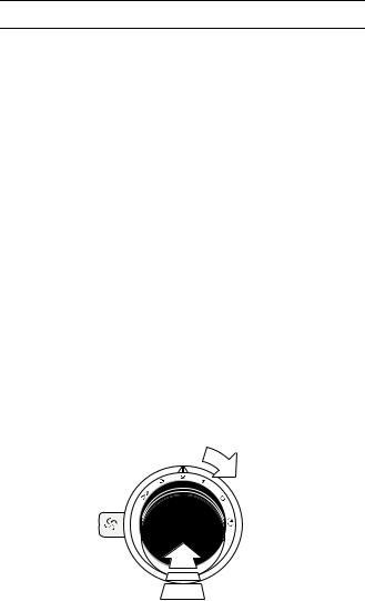
2Press in the control knob and turn the control knob clockwise to the required fan function. The illuminated ring behind the control knob lights up.
Intensive mode
The intensive mode runs for ten minutes. Once this time has elapsed, the ventilation system switches back to fan level 3. The illuminated ring behind the control knob flashes for as long as the control knob is at the intensive mode Ž position after intensive mode has elapsed and at least 1 ventilation element is open.
Switching off
1Turn the control knob to the 0 position.
2Close the locking mechanisms.
8
Run-on function
Ideal for subsequently ventilating the kitchen area. The run-on function can only be used in level 2.
1Open the locking mechanisms.
Note: To switch the fan on, at least one locking mechanism must be open.
2Press in the control knob and turn the control knob anti-clockwise to the run-on function ž. The illuminated ring behind the control knob flashes.
The run-on time is ten minutes. Once this time has elapsed, the ventilation system switches off automatically.
Locking mechanism
ã Risk of burns!
The appliance becomes hot during operation. Only touch the locking mechanism in the marked area.
The ventilation elements can be opened and closed independently of each other. Open the locking mechanisms where you are cooking.
Note: To switch the fan on, at least one locking mechanism must be open.
Opening the locking mechanism
1Press on the marked area " on the locking mechanism.
The locking mechanism is unlocked.
2Swivel the locking mechanism anti-clockwise and press it downwards until it snaps into place.
Closing the locking mechanism
1Press on the marked area " on the locking mechanism.
The locking mechanism is unlocked.
2Swivel the locking mechanism clockwise and press it downwards until it snaps into [place.
Ventilation moulding
If the downdraft ventilation operates beside a gasfired appliance, a ventilation moulding AA 414 010 must be attached when cooking. The ventilation moulding improves the extraction behaviour for gasfired appliances. The ventilation moulding prevents small flames from going out as a result of a draft.
9

Cleaning
ã Risk of burns!
The appliance becomes hot during operation. Allow the appliance to cool down before cleaning.
ã Risk of electric shock!
Penetrating moisture may cause an electric shock. Do not use any high-pressure cleaners or steam cleaners.
ã Risk of injury!
Components inside the appliance may have sharp edges. Wear protective gloves.
Caution! Risk of surface damage: Do not use these cleaners
‒harsh or abrasive cleaning agents
‒oven cleaners
‒corrosive or aggressive cleaners, or those containing chlorine
‒cleaning agents with a high alcohol content
‒hard and scratchy sponges, brushes or scouring pads
If such an agent comes into contact with the appliance, wash it off immediately with water. Thoroughly wash out new sponge cloths before using them!
Cleaning the appliance
Note: Remove any jewellery from arms and hands before cleaning.
Clean the appliance after each time you use it but only once it has cooled down. Remove any overflowing liquid immediately and do not allow food residues to dry in.
The locking mechanism can be removed for cleaning; see section "Removing the metal grease filter". The locking mechanism can be cleaned in the dishwasher. Also clean the inside of the downdraft ventilation regularly. For stubborn dirt, you can use a special grease remover (order number 311297).
Appliance part/ |
Recommended cleaning |
surface |
|
|
|
Stainless steel |
Detergent solution – dry using a soft |
surfaces |
cloth. Only use a little water when clean- |
|
ing – no water must get into the appli- |
|
ance. |
|
On areas where dirt has dried in, allow a |
|
little water and washing-up liquid to soak |
|
in. Do not scour the dirt away. |
|
Use our stainless steel cleaner to |
|
remove heavy soiling, yellowing that is |
|
caused by heat, or small patches of rust |
|
on the locking mechanism caused by |
|
cleaning it in the dishwasher (order |
|
number 311413). |
|
|
Controls |
Detergent solution – the cloth must not |
|
be too wet. Use a soft cloth to dry. |
|
|
Cleaning the metal mesh grease filters
ã Risk of fire!
Grease deposits in the grease filter may catch fire.
Clean the grease filter at least every 2 months.
Never operate the appliance without the grease filter.
Notes
‒Do not use any aggressive, acidic or alkaline cleaning agents.
‒When cleaning the metal mesh grease filters, also clean the holder for the metal mesh grease filters in the appliance using a damp cloth.
‒The metal mesh grease filters can be cleaned in the dishwasher or by hand.
In the dishwasher:
Note: When cleaning the ventilation moulding in the dishwasher, light discolouration may occur. This does not have any effect on the function of the metal grease filter.
Do not clean heavily soiled metal grease filters together with dishes.
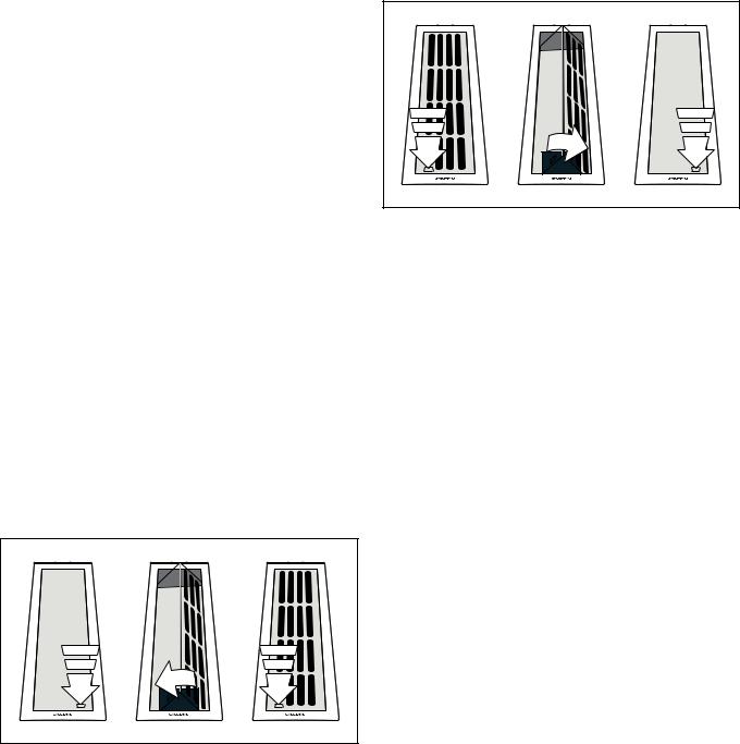
Place the metal grease filter loosely into the dishwasher. Do not let the metal grease filter become jammed.
Place the metal grease filter into the dishwasher with its opening facing downwards.
10
11
Trouble shooting |
|
After-sales service |
Malfunctions often have simple explanations. Please read the following notes before calling the after-sales service.
ã Risk of electric shock!
Incorrect repairs are dangerous. Repairs may only be carried out and damaged power cables replaced by one of our trained after-sales technicians. If the appliance is defective, unplug the appliance from the mains or switch off the circuit breaker in the fuse box. Contact the after-sales service.
Malfunction table
Problem |
Possible cause |
Solution |
|
|
|
The appliance |
The plug is not |
Connect the appliance |
does not work |
plugged in. |
to the electricity supply |
|
|
|
|
Power cut |
Check whether other |
|
|
kitchen appliances are |
|
|
working |
|
|
|
|
Faulty fuse |
Check in the fuse box to |
|
|
make sure that the fuse |
|
|
for the appliance is OK |
|
|
|
Fan does not |
All ventilation |
Open at least 1 ventila- |
start up |
elements are |
tion element |
|
closed |
|
|
|
|
Fan does not |
Locking mecha- |
The " symbol on the |
run, despite the |
nism is fitted |
locking mechanism |
ventilation ele- |
incorrectly |
must be at the front |
ment being |
|
|
open |
|
|
|
|
|
Our after-sales service is there for you if your appliance needs to be repaired. We will always find the right solution in order to avoid unnecessary visits from a service technician.
When calling us, please give the product number (E no.) and the production number (FD no.) so that we can provide you with the correct advice. The rating plate containing these numbers is found on the underside of the front of the appliance. To access this, open the door of the cupboard in which the appliance is fitted.
You can make a note of the numbers of your appliance and the telephone number of the after-sales service in the space below to save time should it be required.
E no. |
FD no. |
|
|
After-sales serviceO
Please be aware that a visit by an after-sales engineer will be charged if a problem turns out to be the result of operator error, even during the warranty period.
Please find the contact data of all countries in the enclosed customer service list.
To book an engineer visit and product advice GB
IE
AU
NZ
Trust the expertise of the manufacturer, and rest assured that the repair will be carried out by trained service technicians using original spare parts for your domestic appliance.
12

Índice
Indicaciones de seguridad importantes |
14 |
|
|
Protección del medio ambiente |
16 |
Evacuación ecológica |
16 |
|
|
Modos de funcionamiento |
16 |
|
|
Funcionamiento en salida de aire al exterior |
16 |
Funcionamiento con recirculación de aire |
16 |
|
|
Su nuevo aparato |
17 |
Ventilación de la zona de cocción |
17 |
Maneta de mando |
17 |
Indicación en el anillo luminoso |
17 |
Accesorios especiales |
18 |
Accesorio de instalación |
18 |
|
|
Manejo |
18 |
|
|
Antes del primer uso |
18 |
Conectar |
18 |
Apagar |
18 |
Función de marcha en inercia |
19 |
Elemento de cierre |
19 |
Carril de circulación del aire |
19 |
|
|
Limpieza |
20 |
Limpieza del aparato |
20 |
Limpiar el filtro de metal antigrasa |
20 |
Desmontar y montar el filtro metálico antigrasa |
21 |
|
|
¿Anomalías - como reaccionar? |
22 |
|
|
Servicio de Asistencia Técnica |
22 |
Encontrará más información sobre productos, accesorios, piezas de repuesto y servicios en internet: www.gaggenau.com y también en la tienda online: www.gaggenau-eshop.com
13
ã=Indicaciones de seguridad importantes
Leer con atención las siguientes instrucciones. Solo así se puede manejar el aparato de forma correcta y segura. Conservar las instrucciones de uso y montaje para utilizarlas más adelante o para posibles futuros compradores.
Solamente un montaje profesional conforme a las instrucciones de montaje puede garantizar un uso seguro del aparato. El instalador es responsable del funcionamiento perfecto en el lugar de instalación.
Este aparato ha sido diseñado para uso doméstico. Este aparato no puede usarse en exteriores. Vigilarlo mientras está funcionando. El fabricante no asume ninguna responsabilidad en caso de daños derivados de un uso indebido o un manejo incorrecto.
Este aparato puede ser utilizado por niños a partir de 8 años y por personas con limitaciones físicas, sensoriales o psíquicas, o que carezcan de experiencia y conocimientos, siempre y cuando sea bajo la supervisión de una persona responsable de su seguridad o que le haya instruido en el uso correcto del aparato siendo consciente de los daños que se pudieran ocasionar.
No dejar que los niños jueguen con el aparato. La limpieza y el mantenimiento rutinario no deben encomendarse a los niños a menos que sean mayores de 8 años y lo hagan bajo supervisión.
Mantener los niños menores de 8 años alejados del aparato y del cable de conexión.
No aspirar materiales y vapores peligrosos o explosivos.
Asegurarse de que no accedan piezas pequeñas o líquidos en el aparato.
Comprobar el aparato al sacarlo de su embalaje. El aparato no debe conectarse en caso de haber sufrido daños durante el transporte.
Este aparato no está previsto para el funcionamiento con un reloj temporizador externo o un mando a distancia.
¡Peligro de asfixia!
El material de embalaje es peligroso para los niños. No dejar que los niños jueguen con el material de embalaje.
¡Peligro mortal!
Los gases de combustión que se vuelven a aspirar pueden ocasionar intoxicaciones. Garantice una entrada de aire suficiente si el aparato se emplea en modo de funcionamiento en salida de aire al exterior junto con un equipo calefactor dependiente del aire del recinto de instalación.
Los equipos calefactores que dependen del aire del recinto de instalación (p. ej., calefactores de gas, aceite, madera o carbón, calentadores de salida libre, calentadores de agua) adquieren aire de combustión del recinto de instalación y evacuan los gases de escape al exterior a través de un sistema extractor (p. ej., una chimenea).
En combinación con una campana extractora conectada se extrae aire de la cocina y de las habitaciones próximas; sin una entrada de aire suficiente se genera una depresión. Los gases venenosos procedentes de la chimenea o del hueco de ventilación se vuelven a aspirar en las habitaciones.
Por tanto, asegurarse de que siempre haya una entrada de aire suficiente.
Un pasamuros de entrada/salida de aire no es garantía por sí solo del cumplimiento del valor límite.
A fin de garantizar un funcionamiento seguro, la depresión en el recinto de instalación de los equipos calefactores no debe superar 4 Pa (0,04 mbar). Esto se consigue si, mediante aberturas que no se pueden cerrar, p. ej., en puertas, ventanas, en combinación con un pasamuros de entrada/salida de aire o mediante otras medidas técnicas, se puede
14
Loading...