


*DJJHQDX
Installation instructions2
Notice de montage16
Instrucciones de instalación30
VG 232 220 CA
Gas cooktop
Table de cuisson gaz
Encimera a gas

en-us
Table of Contents
9 Safety Definitions |
2 |
|
|
IMPORTANT SAFETY INSTRUCTIONS |
3 |
Appliance Handling Safety |
4 |
Safety Codes and Standards |
4 |
Electric Safety |
5 |
Gas Safety |
5 |
Propane Gas Installation |
6 |
Related Equipment Safety |
6 |
|
|
Before you begin |
8 |
Tools and parts needed |
8 |
Parts included |
8 |
Installation accessories |
8 |
Cabinet Requirements |
8 |
Countertop Requirements |
9 |
Technical Data |
9 |
|
|
Installation Procedure |
9 |
Prepare Installation Space |
9 |
Install Appliance |
9 |
Connect Gas Supply |
10 |
Connect Electrical Supply |
10 |
Burner Cap Placement |
10 |
Check the Installation |
11 |
|
|
Removing the appliance |
11 |
|
|
Conversion to another type of gas |
11 |
|
|
Customer Service |
15 |
The wiring diagram is available on the last page of this manual.
Additional information on products, accessories, replacement parts and services can be found at www.gaggenau.com and in the online shop www.gaggenau.com/zz/store
9 Safety Definitions
9 WARNING
This indicates that death or serious injuries may occur as a result of non-observance of this warning.
9 CAUTION
This indicates that minor or moderate injuries may occur as a result of non-observance of this warning.
NOTICE
This indicates that damage to the appliance or property may occur as a result of non-compliance with this advisory.
Note: This alerts you to important information and/or tips.
2
9 IMPORTANT SAFETY INSTRUCTIONS
READ AND SAVE THESE INSTRUCTIONS
:$51,1* ,I WKH LQIRUPDWLRQ LQ WKHVH LQVWUXFWLRQV LV QRW IROORZHG H[DFWO\ D ILUH RU H[SORVLRQ PD\ UHVXOW FDXVLQJ SURSHUW\ GDPDJH SHUVRQDO LQMXU\ RU GHDWK
²'R QRW VWRUH RU XVH JDVROLQH RU RWKHU IODPPDEOH YDSRUV DQG OLTXLGV LQ WKH YLFLQLW\ RI WKLV RU DQ\ RWKHU DSSOLDQFH
²:+$7 72 '2 ,) <28 60(// *$6'R QRW WU\ WR OLJKW DQ\ DSSOLDQFH'R QRW WRXFK DQ\ HOHFWULFDO VZLWFK'R QRW XVH DQ\ SKRQH LQ \RXU EXLOGLQJ
,PPHGLDWHO\ FDOO \RXU JDV VXSSOLHU IURP D QHLJKERU·V SKRQH )ROORZ WKH JDV VXSSOLHU·V LQVWUXFWLRQV,I \RX FDQQRW UHDFK \RXU JDV VXSSOLHU FDOO WKH ILUH GHSDUWPHQW
²,QVWDOODWLRQ DQG VHUYLFH PXVW EH SHUIRUPHG E\ D TXDOLILHG LQVWDOOHU VHUYLFH DJHQF\ RU WKH JDV VXSSOLHU
3
9 IMPORTANT SAFETY INSTRUCTIONS
READ AND SAVE THESE INSTRUCTIONS
IMPORTANT: THE APPLIANCE MUST BE INSTALLED BY A QUALIFIED INSTALLER.
INSTALLER: LEAVE THESE INSTRUCTIONS WITH THE APPLIANCE AFTER INSTALLATION IS COMPLETE. IMPORTANT: SAVE FOR THE LOCAL INSPECTOR’S USE.
9WARNING
If the information in this manual is not followed exactly, fire or shock may result causing property damage or personal injury.
9WARNING
Do not repair, replace or remove any part of the appliance unless specifically recommended in the manuals. Improper installation, service or maintenance can cause injury or property damage. Refer to this manual for guidance. All other servicing should be done by an authorized servicer.
Improper installation is not covered by the warranty.
Appliance Handling Safety
Hidden surfaces may have sharp edges. Use caution when reaching behind or under appliance.
Safety Codes and Standards
This appliance complies with one or more of the following Standards:
UL 858, The Standard for the Safety of Household Electric Ranges
UL 923, The Standard for the Safety of Microwave Cooking Appliances
UL 507, The Standard for the Safety of Electric Fans
ANSI Z21.1 / CSA 1.1 Household Cooking Gas Appliances
CAN/CSA-C22.2 No. 113-M1984 Fans and Ventilators
CAN/CSA-C22.2 No. 61-M89 Household Cooking Ranges
It is the responsibility of the owner and the installer to determine if additional requirements and/or standards apply to specific installations.
Installation must conform with local codes or, in the absence of local codes, with the National Fuel Gas Code, ANSI Z223.1/NFPA 54 or, in Canada, the Natural Gas and Propane Installation Code, CSA B149.1.
The appliance must be electrically grounded in accordance with local codes or, in the absence of local codes, with the National Electrical Code, NFPA 70 latest edition or, in Canada, the Canadian Electric Code, CSA C22.1-02.
4
9 IMPORTANT SAFETY INSTRUCTIONS
READ AND SAVE THESE INSTRUCTIONS
Electric Safety
9WARNING
Before you plug in an electrical cord or turn on power supply, make sure all controls are in the OFF position.
For appliances equipped with a cord and plug, do not cut or remove the ground prong. It must be plugged into a matching grounding type receptacle to avoid electrical shock. If there is any doubt as to whether the wall receptacle is properly grounded, the customer should have it checked by a qualified electrician.
Do not use an extension cord.
Do not use an adapter.
If required by the National Electrical Code (or Canadian Electrical Code), this appliance must be installed on a separate branch circuit.
The circuit breaker should have a contact separation of at least 3 mm on all poles.
Be sure your appliance is properly installed and grounded by a qualified technician. Installation, electrical connections and grounding must comply with all applicable codes.
Before installing, turn power OFF at the service panel. Lock service panel to prevent power from being turned ON accidentally.
Installer – show the owner the location of the circuit breaker or fuse. Mark it for easy reference.
Gas Safety
Install a gas shutoff valve near the appliance. It must be easily accessible in an emergency.
Leak testing must be conducted by the installer according to the instructions in this manual.
The appliance and its individual shutoff valve must be disconnected from the gas supply piping system during any pressure testing at pressures in excess of ½ psi (3.5 kPa).
The appliance must be isolated from the gas supply piping system by closing its individual manual shutoff valve during any pressure testing of the gas supply piping system at test pressures equal to or less than ½ psi (3.5 kPa).
The minimum supply pressure must be 1" water column above the manifold pressure printed on the rating label.
The maximum supply pressure must not exceed 14.0 inches water column (34.9 Millibars).
IMPORTANT SAFETY NOTICE: Burning gas cooking fuel generates some byproducts which are on the list of substances which are known by the State of California to cause cancer or reproductive harm. To minimize exposure to these substances, always operate this unit according to the instructions contained in this booklet and provide good ventilation.
5

9 IMPORTANT SAFETY INSTRUCTIONS
READ AND SAVE THESE INSTRUCTIONS
Proposition 65 Warning:
This product may contain a chemical known to the State of California, which can cause cancer or reproductive harm. Therefore, the packaging of your product may bear the following label as required by California:
67$7( 2) &$/,)251,$ 352326,7,21 :$51,1*
:$51,1*
&DQFHU DQG 5HSURGXFWLYH +DUP ZZZ 3 :DUQLQJV FD JRY
Propane Gas Installation
The propane gas tank must be equipped with its own high pressure regulator. In addition, the regulator supplied with this unit must also be used.
The appliance is shipped from the factory for use with natural gas. It must be converted for use with propane. A qualified technician or installer must do the conversion.
For use with propane the appliance must be converted per the LP conversion instructions.
For Massachusetts installations:
Installation must be performed by a qualified or licensed contractor, plumber or gas fitter qualified or licensed by the state, province or region where this appliance is being installed.
Shut-off valve must be a “T” handle gas cock.
Flexible gas connector must not be longer than 36 inches.
Installer - show the owner where the gas shut-off valve is located.
Related Equipment Safety
The appliance should only be used if installed by a qualified technician in accordance with these installation instructions. The manufacturer is not responsible for any damage resulting from incorrect installation.
Remove all tape and packaging before using the appliance. Destroy the packaging after unpacking the appliance. Never allow children to play with packaging material.
Never modify or alter the construction of the appliance. For example, do not remove leveling legs, panels, wire covers or anti-tip brackets/screws.
To eliminate the risk of burns or fire by reaching over heated surface units, cabinet storage space located above the surface units should be avoided. If cabinet storage is to be provided, the risk can be reduced by installing a hood that projects horizontally a minimum of 5 inches (127 mm) beyond the bottom of the cabinet.
Verify that cabinets above the cooktop are a maximum of 13" (330 mm) deep.
When installing a cooktop over a single oven, be sure to follow both the oven’s and cooktop’s installation manuals.
6
9 IMPORTANT SAFETY INSTRUCTIONS
READ AND SAVE THESE INSTRUCTIONS
Ventilation Recommendations
We strongly recommend the installation of a ventilation hood above this appliance. The hood must be installed according to instructions furnished with the hood.
9CAUTION
The appliance should not be installed with a ventilation system that blows air downward toward the burners. This type of ventilation system may cause ignition and combustion problems with the gas cooking appliance resulting in personal injury or unintended operation.
7
en-us Before you begin
Before you begin
Tools and parts needed
Phillips Head Screwdriver
Pencil
Drill with ¼" (6 mm) bit
Jigsaw
Tape Measure
Note: Additional materials may be necessary for installation in solid surface countertops. Contact the countertop manufacturer.
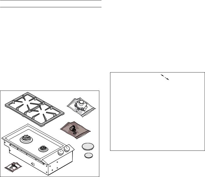
Parts included
Burner grate
Burner caps
Pressure regulator
1/2” U.S.A. elbow and fiber gasket
Plastic covering parts for installation without appliance cover
Installation accessories
VD 200 020 Black appliance cover
VV 200 010 Stainless steel connection strip for combining with other Vario 200 appliances
VV 200 020 Black connection strip for combining with other Vario 200 appliances
Use the accessories only as indicated. The manufacturer assumes no liability for incorrect usage of the accessories.
Cabinet Requirements
* |
|
|
( |
) |
|
& |
||
|
||
|
% |
|
' |
|
|
$ |
|
The minimum spaces that must be maintained when installing the gas cooktop shall be:
Aminimum 12" (300 mm)
Bminimum 12" (300 mm)
Cminimum 30" (762 mm) clearance between the top of the cooking surface and the bottom of combustible constructions
Dminimum 1 9/16" (40 mm)
Eminimum 24" (600 mm)
Fminimum 18" (460 mm)
Gmaximum 13" (330 mm)
The distance from the top of the cooktop to the bottom of cabinets above can be reduced to 26" when the bottom of the wood or metal cabinet is protected by not less than ¼" (6.35 mm)-thick flame-retardant millboard covered with not less than No. 28 MSG sheet metal, 0.015 inch (0.4 mm) stainless steel, 0.024 inch (0.6 mm) aluminum or copper.
8
Countertop Requirements
9 WARNING
To reduce the risk of ignition of surrounding combustible materials, install at least 12" (300 mm) from both sidewalls and at least 2" (51 mm) from the rear wall.
The countertop must be level and horizontal. The stability of the countertop must be maintained after the cut-out has been made.
|
¡ |
|
|
PP |
|
|
[ |
|
|
PLQ PP |
|
|
|
|
|
|
PP |
|
|
|
|
PLQ |
|
|
|
|
|
PLQ |
|
|
|
|
|
|
|
|
PLQ |
|
PLQ |
|
|
Technical Data
Total connected load electric |
10 |
W |
Total connected load gas |
16,500 |
BTU/h |
(natural gas) |
(4.9 kW) |
|
|
|
|
Total connected load gas |
16,500 |
BTU/h |
(propane gas) |
(4.9 kW) |
|
|
|
|
Installation Procedure en-us
Installation Procedure
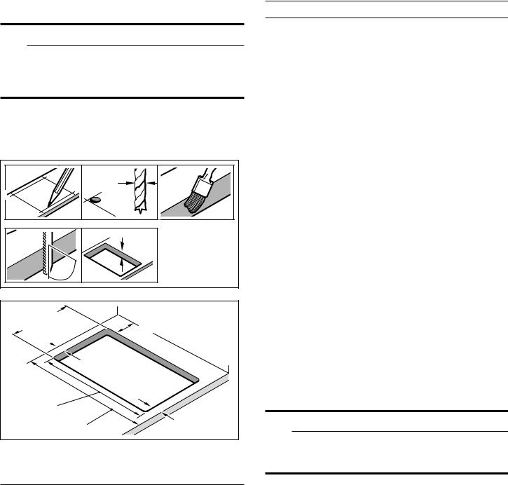
Prepare Installation Space
The kitchen unit must be heat-resistant to at least 200° F (90°C). The stability of the unit must be maintained after producing the cut-out.
Create the cut-out in the countertop for one or several Vario appliances according to the installation diagram. The angle of the cut surface to the countertop must be 90°.
After creating cut-out, remove shavings. Seal cut surfaces in a heat-resistant manner.
Some solid surface countertops require special installations. For example, heat reflective tape and rounded corners may be necessary. Contact the countertop manufacturer for instructions specific to your countertop.
Observe minimum distance between appliance underside and furniture parts of 3/8" (10 mm).
To improve flame stability, we recommend installing an intermediate floor underneath the appliance in the installation cabinet.
When installing multiple Vario appliances: Take into account spacerequirement for VV 200 connection strip between the appliances.Appliances can also be installed in individual cut-outs, bearingin mind a minimum distance between the appliances of 19/16" (40 mm).
Install Appliance
9 WARNING
Before you plug in an electrical cord or turn on power supply, make sure all controls are in the OFF position.
1.Secure the appliance cover VD 200 020 (available separately as special accessories) before fitting on the appliance (see installation instructions
VD 200 020).
9
en-us Installation Procedure
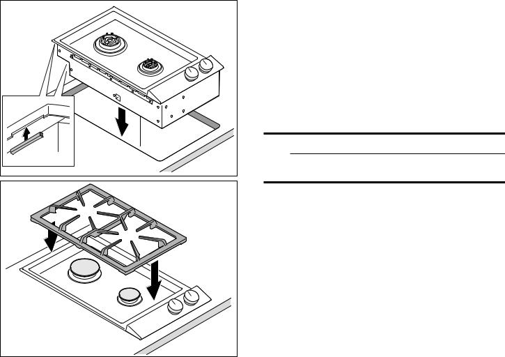
2.Insert appliance evenly into the cutout. Push it firmly into the cutout from above.
Note: The appliance must be firmly fixed in the cutout and must not be able to move around (e.g. during cleaning). If the width of the cutout is at the upper tolerance limit, fasten the ledges at the sides in the cutout if necessary.
The flexible gas line must not come into contact with moving parts of the fitted unit (e.g. drawers) or be laid in areas where it could become trapped or damaged.
The flexible gas line must not come into contact with a cooktop, oven, dishwasher, refrigerator, washing machine, hot water pipe, radiator or any other appliance installed in the vicinity of the gas cooktop.
The flexible gas line must not be subject to rubbing, vibrations, kinking or any other kind of deformation. It should be checked along its entire length with the cooktop in the installation position.
SERVICER INFO ONLY
Connect the gas supply using the ½" U.S.A. elbow and the fiber gasket supplied with the unit. The shorter, nontapered thread fits into the threaded nut on the cooktop. The longer, tapered U.S.A. thread is for the incoming gas supply. Vent the gas line, check for leaks.
9 CAUTION
The gas pressure regulator is supplied with the unit and comes set for natural gas.
Connect Gas Supply
The appliance is shipped from the factory for use with natural gas. It must be converted for use with propane. A qualified technician or installer must do the conversion.
Before connecting the appliance, please check whether the local connection conditions such as gas type and gas pressure match the appliance settings.
Make sure the gas supply is turned off at the manual shutoff valve before connecting the appliance.
The gas connection must be in a location that permits access to the manual shut-off valve and which, if applicable, is visible after opening the door of the cabinet.
Connect Electrical Supply
Before connecting supply cord to wall receptacle, make certain that gas shutoff valve and all burner controls are in OFF position.
Electrical connection (AC 110-120 V) is established by means of a connecting cord with a grounding contact plug connected to a grounded socket, which must also be accessible after installation of the gas cooktop.
Burner Cap Placement
The burner parts must be properly placed for the cooktop to function properly. If the burner parts are not properly placed, one or more of the following problems may occur:
Burner flames are too high.
Flames shoot out of burners.
Burners do not ignite.
Burner flames light unevenly.
Burner emits gas odor.
Placing Burner Parts
After electrical connection is complete, assemble the burner parts correctly and evenly. When assembling the burner parts, make sure that the burner head is placed on the base in such a way that the prongs of the burner cap fit snugly into the groove of the burner base.
10
Checking Burner Cap Placement
Check to make sure that there is no gap between the burner parts. You may gently try to move the burner parts from side to side to check if they are properly placed.
Check the Installation
Check operation of electric igniters. Check flame characteristics. Flame should be blue with no yellow tip.
Yellow Flames:
Further adjustment is required.
Yellow Tips on Outer Cones:
Normal for LPG Gas.
Soft Blue Flames:
Normal for Natural Gas.
If the flame is completely or mostly yellow, verify that the regulator is set for the correct fuel. After adjustment, retest.
Some yellow streaking is normal during the initial startup. Allow unit to operate 4-5 minutes and re-evaluate before making adjustments.
Removing the appliance
Disconnect the appliance from the power and the gas supply. Push out the appliance from below.
9 CAUTION
Risk of damage! Do not lever out the appliance from above.
Conversion to another type of gas en-us
Conversion to another type of gas
The appliance must only be converted to a different type of gas by a licensed expert.
Switch off the power supply and shut off the gas supply before carrying out conversion.
This gas cooktop conforms to the categories indicated on the rating plate. Changing the injection nozzles enables the appliance to be used with all the types of gas listed there. Conversion kits can be obtained from our aftersales service. Some models come delivered with a conversion kit.
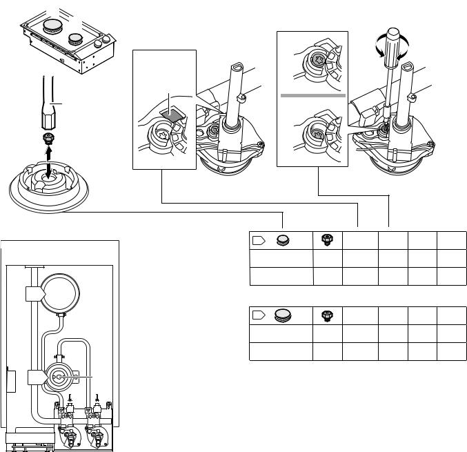
The gas type is changed by:
Replacing the main control jets
Adjusting the gas valves (bypass screws)
The table shows the right combination for the relevant gas type.
Never remove the gas valve shaft. In the event of damage or unusual gas conversion, the entire gas valve must be replaced. Call customer service.
9 CAUTION
To convert regulator to LP (propane) gas:
Make-Maxitrol Model RV 47 CL ½ PSIG
3.Remove the aluminum cap from the top of the regulator.
4.Remove the yellow plastic shaft from the cap by pushing it sideways until it pops out of the groove in the cap.
5.Turn the shaft over and push back into the cutout in the cap.
6.Replace the cap on the regulator.
11
en-us Conversion to another type of gas
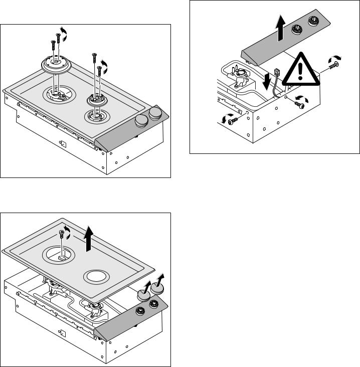
Replacing the main control nozzles:
1.Remove the pan support and all burner parts.
2.Undo the fastening screws on the burners (two screws on each burner). Lift the burners upwards and remove them.
3.Undo the earthing screw on the rear burner. Carefully lift the hob upwards and remove it.
4.Remove the control knob.
5.Undo the fastening screws on the control panel. Remove the control panel and disconnect the connection cable on the back of the control panel.
6.Replace the nozzles. You can obtain a key from our customer service (order number 00424699). Take care not to break the nozzles when (un)screwing them.
7.Screw the new nozzles in as far as possible to obtain a tight seal.
12
Conversion to another type of gas en-us
% |
|
|
$ |
XS |
|
|
|
|
|
XS |
GRZQ |
|
)5' |
|
|
&RGH |
|
|
GRZQ |
|
|
|
%
 E
E
$ |
D |
$ |
|
)5' &RGH |
0 |
4Q |
%78 K |
1* $ :& |
|
-+ |
XS |
N: |
|
3URSDQH :& |
|
-+ |
GRZQ |
N: |
|
% |
|
)5' &RGH |
0 |
4Q |
%78 K |
1* $ :& |
|
-- |
XS |
N: |
|
3URSDQH :& |
|
-- |
GRZQ |
N: |
|
13

en-us Conversion to another type of gas
Adjusting the gas valves
9 WARNING
Risk of damage!
Do not over-tighten the bypass screws.
If necessary, adjust the bypass screws M using a Torx screwdriver (see table):
up: The bypass screws must be flush with the top edge of the frame.
down: The bypass screws must be screwed in fully.
Assembly:
1.Connect the connection cable on the back of the control panel. Put the control panel in place and screw it in evenly.
2.Attach the control knobs.
3.Put the hob in place and screw in the earthing screw on the rear burner.
4.Put the burners in place and screw them on, making sure that the seal is seated correctly.
5.Put the burner parts and pan supports in place, making sure they are positioned correctly.
Check that the appliance is working after conversion:
Yellow tips must not be visible on the flames. When turning the control knob quickly between the highest and the lowest setting, the burner must not go out and flashback must not occur.
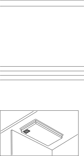
Note: Attach the sticker showing the new gas type next to the rating plate on the appliance.
Save the nozzles removed from the appliance for future use.
14
Customer Service en-us
Customer Service
If your appliance needs repairs, our customer service is there for you. We work hard to help solve problems quickly and without unnecessary service calls, getting your appliance back up and running correctly in the least amount of time possible.
When you call, please indicate the product number
(E-Nr.) and serial number (FD-Nr.) so that we can support you in a qualified manner. You will find the type plate with these numbers on the bottom of the appliance. To avoid having to search for a long time when you need it, you can enter your appliance data and the customer support telephone number here.
E-Nr. FD-Nr.
Customer Service O
Please read the use and care instructions provided with your appliance. Failure to do so may result in an error in using the appliance. This could result in a service call that instead of fixing a mechanical issue is only needed for customer education. Such calls are not covered by the appliance warranty.
Please find the contact data of all countries in the enclosed customer service list.
To book a service visit and product advice
USA
CANADA
15
 Loading...