


INMARSAT-C
MOBILE EARTH STATION
FELCOM 15
www.furuno.co.jp

The paper used in this manual is elemental chlorine free.
9-52 Ashihara-cho,
Nishinomiya, 662-8580, JAPAN
Telephone : +81-(0)798-65-2111
Fax |
: +81-(0)798-65-4200 |
All rights reserved. |
Printed in Japan |
Pub. No. OME-56350-H2
(TATA ) FELCOM15
FURUNO Authorized Distributor/Dealer
A : DEC. 2002
H2 : MAY 23, 2007
*00080934915*
*00080934915*
* 0 0 0 8 0 9 3 4 9 1 5 *

 SAFETY INSTRUCTIONS
 WARNING
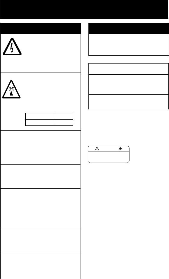
Do not open the equipment.
Hazardous voltage which can cause electrical shock, burn or serious injury exists inside the equipment. Only qualified personnel should work inside the equipment.
Hazardous microwave. Do not approach within
60 cm of the antenna radome when it is transmitting.
Microwave radiation can be harmful to the human body, particularly the eyes.
Radiation Level At
10W/m2 |
0.6 m |
Leave the equipment powered while underway. (For antenna maintenance and the like, turn off the power at the mains switchboard.)
Distress cannot be communicated unless the equipment is powered.
Do not disassemble or modify the equipment.
Fire, electrical shock or serious injury can result.
Turn off the power immediately at the ship's mains switchboard if water leaks into the equipment or the equipment is emitting smoke or fire.
Continued use of the equipment can cause fire or electrical shock. Contact your dealer for advice.
Do not locate the terminal unit near water or places subject to water splash.
Electrical shock, fire or personal injury may resullt
Any repair work must be done by a licensed radio technician.
Improper repair work can cause electrical shock or fire.
 WARNING
Do not operate the equipment with wet hands.
Electrical shock may result.
 CAUTION
Use the proper fuse.
Use of a wrong fuse can result in fire or permanent damage to the equipment.
This equipment is intended for marine application.
WARNING LABEL
A warning label is attached to the terminal unit. Do not remove the label. If the label is missing or damaged, contact your dealer about replacement.
WARNING |
Name: Warning Label (2) |
|
|
To avoid electrical shock, do not |
Type: 03-129-1001-1 |
remove cover. No user-serviceable |
Code No.: 100-236-741 |
parts inside. |
i
TABLE OF CONTENTS
|
|
|
|
........................................................................................................FOREWORD |
vi |
||
SYSTEM CONFIGURATION.............................................................................. |
viii |
||
INMARSAT C SYSTEM OVERVIEW ................................................................... |
ix |
||
1. OPERATIONAL OVERVIEW......................................................................... |
1-1 |
||
1.1 |
Terminal Unit ............................................................................................................. |
1-1 |
|
|
1.1.1 Turning the power on/off ................................................................................. |
1-1 |
|
|
1.1.2 |
DISTRESS button........................................................................................... |
1-1 |
|
1.1.3 |
Diagnostics ..................................................................................................... |
1-1 |
|
1.1.4 Floppy disk drive, floppy disks ........................................................................ |
1-2 |
|
|
1.1.5 |
Audio alarm..................................................................................................... |
1-2 |
|
1.1.6 |
Adjusting brilliance.......................................................................................... |
1-2 |
1.2 |
Keyboard................................................................................................................... |
1-3 |
|
|
1.2.1 |
Key description ............................................................................................... |
1-3 |
|
1.2.2 |
Shortcut keys.................................................................................................. |
1-5 |
|
1.2.3 |
Function key description ................................................................................. |
1-5 |
1.3 |
Distress Alert/Received Call Unit IC-305, Alarm Unit IC-306...................................... |
1-6 |
|
1.4 |
Printer PP-510 (option).............................................................................................. |
1-7 |
|
1.5 |
Standby Display......................................................................................................... |
1-8 |
|
|
1.5.1 |
Display indications .......................................................................................... |
1-9 |
1.6 |
Menu Overview ....................................................................................................... |
1-13 |
|
1.7 |
Error Messages and Alerts ...................................................................................... |
1-14 |
|
1.8 |
Using a PC (local supply) ........................................................................................ |
1-15 |
|
|
1.8.1 |
Installing software ......................................................................................... |
1-15 |
|
1.8.2 Starting up, quitting the application ............................................................... |
1-19 |
|
2. SYSTEM INITIALIZATION ............................................................................ |
2-1 |
||
2.1 |
System Settings ........................................................................................................ |
2-1 |
|
|
2.1.1 |
Confirming the main terminal .......................................................................... |
2-1 |
|
2.1.2 |
System setup.................................................................................................. |
2-2 |
2.2 |
Terminal Setup .......................................................................................................... |
2-6 |
|
2.3 |
Login and Logout....................................................................................................... |
2-8 |
|
|
2.3.1 |
Login............................................................................................................... |
2-8 |
|
2.3.2 |
Logout........................................................................................................... |
2-10 |
2.4 |
EGC Settings ........................................................................................................... |
2-11 |
|
|
2.4.1 What is the EGC (Enhanced Group Call) service?......................................... |
2-11 |
|
|
2.4.2 |
EGC setup .................................................................................................... |
2-13 |
|
2.4.3 |
Adding EGC channels................................................................................... |
2-16 |
|
2.4.4 Saving, printing EGC messages automatically.............................................. |
2-18 |
|
2.5 |
Adding NCS Channels............................................................................................. |
2-20 |
|
2.6 |
LES List................................................................................................................... |
2-22 |
|
|
2.6.1 |
Displaying toll charges .................................................................................. |
2-22 |
|
2.6.2 Registering LES to LES list........................................................................... |
2-24 |
|
|
2.6.3 Editing the LES list........................................................................................ |
2-25 |
|
|
2.6.4 |
Printing the LES list....................................................................................... |
2-26 |
ii
2.7 |
Station List............................................................................................................... |
2-27 |
|
2.7.1 Adding stations to the station list ................................................................... |
2-27 |
|
2.7.2 Editing the station list .................................................................................... |
2-30 |
|
2.7.3 Printing the station list ................................................................................... |
2-31 |
2.8 |
Entering Own Ship’s Position................................................................................... |
2-32 |
2.9 |
Creating a Directory................................................................................................. |
2-33 |
|
2.9.1 Creating a directory where to store messages............................................... |
2-33 |
|
2.9.2 Specifying directory where to store messages............................................... |
2-35 |
2.10 |
E-mail Service/SMS Station List............................................................................... |
2-36 |
2.11 |
E-mail Setup............................................................................................................ |
2-39 |
2.12 |
Saving, Loading System Settings ............................................................................ |
2-40 |
|
2.12.1 Saving system settings to a floppy disk ......................................................... |
2-40 |
|
2.12.2 Loading system settings to the terminal unit.................................................. |
2-40 |
3. FILE OPERATIONS....................................................................................... |
3-1 |
||
3.1 |
Files and Working Areas............................................................................................ |
3-1 |
|
3.2 |
Preparing Files .......................................................................................................... |
3-2 |
|
|
3.2.1 |
Preparing a routine file .................................................................................... |
3-2 |
|
3.2.2 |
Preparing a confidential file ............................................................................. |
3-3 |
|
3.2.3 |
Editor menu setup ........................................................................................... |
3-4 |
|
3.2.4 |
Working with text............................................................................................. |
3-5 |
3.3 |
Saving Files............................................................................................................. |
3-10 |
|
|
3.3.1 |
Formatting a floppy disk ................................................................................ |
3-11 |
|
3.3.2 |
Saving files.................................................................................................... |
3-12 |
3.4 |
Opening Files .......................................................................................................... |
3-14 |
|
|
3.4.1 |
Opening files ................................................................................................. |
3-14 |
|
3.4.2 |
Switching between files ................................................................................. |
3-14 |
|
3.4.3 Opening a file when both working areas are occupied................................... |
3-15 |
|
3.5 |
Saving a File Under a New Name............................................................................ |
3-16 |
|
3.6 |
Printing Files on Floppy Disks.................................................................................. |
3-17 |
|
3.7 |
Combining Files....................................................................................................... |
3-17 |
|
3.8 |
Deleting Files........................................................................................................... |
3-18 |
|
3.9 |
Renaming Files........................................................................................................ |
3-19 |
|
3.10 |
Decoding E-mail Attachment.................................................................................... |
3-20 |
|
4. INMARSAT C COMMUNICATIONS .............................................................. |
4-1 |
||
4.1 |
Transmitting............................................................................................................... |
4-1 |
|
|
4.1.1 |
Code description ............................................................................................. |
4-1 |
|
4.1.2 |
Transmitting prepared message ...................................................................... |
4-2 |
|
4.1.3 Transmitting a file stored on a floppy disk...................................................... |
4-15 |
|
|
4.1.4 Canceling transmission on a message awaiting transmission ....................... |
4-16 |
|
|
4.1.5 |
Requesting delivery status ............................................................................ |
4-17 |
|
4.1.6 Accessing the 2-digit code services............................................................... |
4-20 |
|
|
4.1.7 Displaying the send message log.................................................................. |
4-22 |
|
4.2 |
Receiving................................................................................................................. |
4-23 |
|
|
4.2.1 When a message is received ........................................................................ |
4-23 |
|
|
4.2.2 Setting the receive alarm............................................................................... |
4-24 |
|
|
4.2.3 Displaying, printing received messages......................................................... |
4-25 |
|
iii
|
4.2.4 Automatically printing received messages .................................................... |
4-28 |
|
4.2.5 Saving received messages to a floppy disk................................................... |
4-28 |
|
4.2.6 Automatically saving received messages to a floppy disk ............................. |
4-29 |
|
4.2.7 Deleting received messages......................................................................... |
4-30 |
4.3 |
Log.......................................................................................................................... |
4-31 |
|
4.3.1 Displaying and printing the display log .......................................................... |
4-31 |
|
4.3.2 Automatic printing of display log.................................................................... |
4-32 |
4.4 |
EGC Messages ....................................................................................................... |
4-33 |
|
4.4.1 Displaying and reprinting EGC messages..................................................... |
4-33 |
|
4.4.2 Displaying EGC closed network ID (ENID).................................................... |
4-34 |
|
4.4.3 Receiving EGC distress or urgent message.................................................. |
4-35 |
|
4.4.4 Displaying the EGC message log.................................................................. |
4-35 |
5. DATA REPORTING AND POLLING............................................................... |
5-1 |
||
5.1 |
Data Reporting .......................................................................................................... |
5-1 |
|
|
5.1.1 |
Setting a data report ....................................................................................... |
5-2 |
|
5.1.2 |
Setting a message report................................................................................ |
5-4 |
|
5.1.3 Automatic printing of data report, polling command......................................... |
5-7 |
|
5.2 |
Polling ....................................................................................................................... |
5-8 |
|
|
5.2.1 |
Polling commands........................................................................................... |
5-8 |
|
5.2.2 |
Other polling commands ............................................................................... |
5-10 |
|
5.2.3 |
Polling reception ............................................................................................ |
5-11 |
5.3 |
DNID (Data Network Identification).......................................................................... |
5-12 |
|
|
5.3.1 |
Displaying DNID ........................................................................................... |
5-12 |
|
5.3.2 |
Enabling/Disabling DNID............................................................................... |
5-12 |
6. DISTRESS OPERATIONS ............................................................................ |
6-1 |
|
6.1 |
Transmitting the Distress Alert................................................................................... |
6-1 |
6.2 |
Transmitting the Distress Alert with Nature of Distress Specified ............................... |
6-2 |
6.3 |
Distress Message...................................................................................................... |
6-4 |
6.4 |
Testing the Distress Button........................................................................................ |
6-5 |
7. OTHER FUNCTIONS .................................................................................... |
7-1 |
|
7.1 |
Aborting an Operation ............................................................................................... |
7-1 |
7.2 |
Scanning NCS Common Channel ............................................................................. |
7-2 |
7.3 |
Choosing EGC Receiving Channel............................................................................ |
7-3 |
7.4 |
Choosing NCS Channel ............................................................................................ |
7-4 |
7.5 |
LES Information ........................................................................................................ |
7-5 |
8. E-MAIL BY PC............................................................................................... |
8-1 |
||
8.1 |
Overview ................................................................................................................... |
8-1 |
|
|
8.1.1 |
Overview of mail functions .............................................................................. |
8-1 |
|
8.1.2 |
E-mail restrictions ........................................................................................... |
8-2 |
|
8.1.3 |
E-mail precautions .......................................................................................... |
8-2 |
8.2 |
Connection of FELCOM 15 with single PC ................................................................ |
8-4 |
|
8.3 |
Function Settings....................................................................................................... |
8-5 |
|
|
8.3.1 Setting IP address and subnet mask............................................................... |
8-5 |
|
|
8.3.2 |
Enabling DHCP settings.................................................................................. |
8-6 |
|
8.3.3 |
Gateway setting .............................................................................................. |
8-7 |
iv

|
8.3.4 |
Restricting access ........................................................................................... |
8-8 |
|
8.3.5 Restricting outgoing message size .................................................................. |
8-9 |
|
|
8.3.6 |
Automatically converting attachments ........................................................... |
8-10 |
|
8.3.7 Connection of FELCOM 15 to shipboard LAN mail server............................. |
8-11 |
|
|
8.3.8 |
Selective forwarding...................................................................................... |
8-13 |
8.4 |
E-mail Client Setup Example ................................................................................... |
8-15 |
|
8.5 |
SMTP Error Messages............................................................................................. |
8-16 |
|
9. MAINTENANCE, TROUBLESHOOTING...................................................... |
9-1 |
||
9.1 |
General Checking and Maintenance.......................................................................... |
9-1 |
|
9.2 |
Diagnostics................................................................................................................ |
9-2 |
|
|
9.2.1 Self test at power on........................................................................................ |
9-2 |
|
|
9.2.2 Testing the terminal unit through the keyboard, displaying program |
|
|
|
|
version no. ...................................................................................................... |
9-2 |
9.3 |
Performance Verification (PV) Test ............................................................................ |
9-3 |
|
|
9.3.1 |
PV test sequence ............................................................................................ |
9-3 |
|
9.3.2 |
PV test procedure............................................................................................ |
9-4 |
|
9.3.3 Displaying PV test results................................................................................ |
9-5 |
|
9.4 |
System Status Monitor............................................................................................... |
9-6 |
|
9.5 |
Replacing the Battery................................................................................................. |
9-8 |
|
9.6 |
Replacing the Fuse.................................................................................................... |
9-8 |
|
9.7 |
Error Messages ......................................................................................................... |
9-9 |
|
|
9.7.1 |
Equipment trouble messages .......................................................................... |
9-9 |
|
9.7.2 |
Warning messages........................................................................................ |
9-10 |
APPENDIX ...................................................................................................... |
AP-1 |
Menu Tree....................................................................................................................... |
AP-1 |
International Telex/Telephone Country Code List ............................................................ |
AP-9 |
LES List ........................................................................................................................ |
AP-17 |
International Telex Abbreviations................................................................................... |
AP-18 |
International Telegraphy Alphabet ................................................................................. |
AP-19 |
Messages ..................................................................................................................... |
AP-20 |
Digital Interface (IEC 61162-1 2nd Edition)..................................................................... |
AP-23 |
Parts List....................................................................................................................... |
AP-34 |
Parts Location............................................................................................................... |
AP-36 |
SPECIFICATIONS........................................................................................... |
SP-1 |
INDEX .............................................................................................................. |
IN-1 |
Declaration of conformity |
|
v

FOREWORD
Introduction
FURUNO Electric Company thanks you for considering and purchasing the FELCOM 15 Inmarsat C Mobile Earth Station. We are confident you will discover why the FURUNO name has become synonymous with quality and reliability.
Mainly consisting of an antenna unit and a terminal unit, the FELCOM 15 provides the full range of distress and general communication services for mobile and fixed terrestrial subscribers in the Inmarsat C communication network. Its compact size permits installation where space is limited.
FURUNO designs and manufactures this equipment with much attention to operation and maintenance simplicity. However, please read and follow the recommended procedures for operation and maintenance to get the most out of the equipment.
This manual provides a brief introduction to the Inmarsat C system (pages ix thru xiv). For more detailed information, refer to the information below.
Inmarsat C Maritime Customer Relations Officer
Maritime Services Operations Department
International Maritime Satellite Organization (Inmarsat)
Address: |
99 City |
Road, London, EC1Y 1AX, UK |
|
Telephone: |
+44 |
20 |
7728 1777 (Switchboard) |
Fax: |
+44 |
20 |
7728 1142 |
URL: |
www.inmarsat.com |
||
customer_care@inmarsat.com |
|||
vi
Features
•Conforms to the following standards: IMO A.807(19), MSC.68(68) Annex 4, MSC/Cir 682, IMO A.694(17), IEC 61097-4 (1994), IMO A.664(16),
IEC 60945 (2002), IEC 61162-1 (2000).
•E-mail facility. (To send E-mail, register with an LES which provides e-mail services.)
•Built-in Enhanced Group Call (EGC) receiver permits operation as EGC-only receiver.
•Terminal unit accepts a wide variety of peripheral equipment: Distress Message Controller (DMC), PC, navigator, etc.
•Connection of external terminal unit for operation from remote location such as the bridge.
•Store-and-forward telex communication (public telex network)
•Data reporting and Polling
•GPS receiver (option) built in the terminal unit provides GPS-generated position.
•Diagnostic programs for maintenance
•Terminal unit provides a floppy disk drive for storage of received and transmitted messages on floppy disks.
•Menu driven operation
Program Number
PC Board |
Program No. |
Version No. |
Date of Modification |
RF CON CPU |
1650159 |
03 |
5/2004 |
TERM CPU |
1650162 |
03 |
5/2004 |
vii
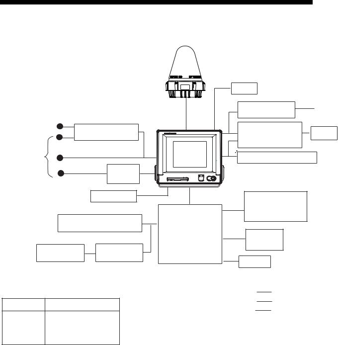
SYSTEM CONFIGURATION
ANTENNA
UNIT
IC-115
SHIP'S MAINS |
|
|
100/115/220/230 VAC |
TERMINAL UNIT |
|
1φ, 50/60 Hz |
||
IC-215 |
||
|
AC-DC Power Supply |
|
|
PR-240 |
|
SHIP'S MAINS |
GPS receiver |
|
12/24 VDC |
OP16-24 |
Printer**
PP-510
* For 12 VDC ship's mains,
DC-DC converter is Mini Keyboard required to use PP-510.
Distress Message Controller |
|
||
|
DMC-5 |
JUNCTION |
|
|
|
||
|
OR |
BOX |
|
|
IC-315 |
||
SSAS Alert Unit |
SSAS Alert Unit |
||
|
|||
IC-307 |
IC-307 |
|
|
(Max. 3 units) |
|
||
** = Mandatory for EGC operation as required by IMO RES. A.664(16).
CATEGORY OF UNITS
Unit Category
Terminal Unit |
Protected from weather |
|
|
|
|
Antenna Unit |
Exposed to weather |
|
|
|
|
Other Units |
Protected from weather |
|
DGPS
EGC Printer** |
24 VDC |
|
PP-505 |
||
|
Personal
Computer Printer (PC/AT compatible)
Shipboard LAN (Ethernet)
Distress Alert/
Received Call Unit
IC-305
Alarm Unit
IC-306
Navigator
:Standard Supply
:Option
:Local Supply
viii
INMARSAT C SYSTEM OVERVIEW
Introduction
The Inmarsat C system provides worldwide telex and data transmission and reception of written information to owners of an Inmarsat C transceiver or a terrestrial telex network via satellite. Further, e-mail can be sent via the internet.
Communication mode is store-and-forward telex, which means all information sent are first stored at an LES and then delivered to designated party.
An EGC (Enhanced Group Call) receiver is built in the FELCOM 15 to receive the following types of messages, broadcast by LESs:
•SafetyNETTM-governments and maritime authorities can use this service to distribute maritime safety information to ships within selected areas.
•FleetNETTM-commercial subscription organizations or shipping companies can use this service to transmit trade information (for example, company news or market prices) simultaneously to a selected group of ships, to provide up-to-the-minute information.
•EGC system-related is sent by Inmarsat to certain shipping companies and geographical areas.
FELCOM 15 allows you to make distress calls. They are given immediate priority over all other calls, and are automatically routed to a land-based Rescue Co-ordination Centre (RCC).
Besides its primary application of ship-shore, shore-ship or ship-ship communications, the Inmarsat C service has also proved beneficial to trucking firms who have found it indispensable for communicating with their vehicles. In this manual, however, we will concentrate on ship applications, the main application.
ix
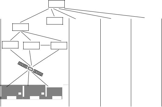
INMARSAT C SYSTEM
Inmarsat C System Configuration
OCC
SCC
NCS
LES LES LES
Same as left |
Same as left Same as left |
Satellite
|
|
|
|
|
|
|
MES |
|
|
|
||
|
|
|
|
|
|
|
|
|
||||
|
|
|
|
|
|
|
|
|
|
|
|
|
|
0.0 |
m |
|
0.0 |
m |
|
|
0.0 |
m |
|
|
|
|
|
|
|
|
|
|
|
|
|
|
|
|
-/+: To set option |
|
|
-/+: To set option |
|
|
-/+: To set option |
|
|
|
|
|
|
|
|
|
|
|
|
|
|
|
|
AOR-East |
IOR |
POR |
|
|
|
|
|
|
|
|
|
|
|||
|
|
|
AOR-West |
|
|
|||||||
OCC: Operation Control Center
SCC: Satellite Control Center
NCS: Network Coordination Station
MES: Mobile Earth Station
LES: Land Earth Station
Inmarsat C system configuration
x
INMARSAT C SYSTEM
The Inmarsat C system consists of the Operation Control Center (OCC), Satellite Control Centers (SCC), Network Coordination Stations (NCS), Land Earth Stations (LES) and Mobile Earth Stations (MES). The OCC, located at Inmarsat’s London headquarters, coordinates a wide range of activities in the Inmarsat system, including commissioning of mobile earth stations.
The Inmarsat C system divides the world into four regions and each region is covered by its own satellite.
Inmarsat system satellites
Region |
Satellite |
Satellite Position |
AOR-West |
Inmarsat 3, F4 |
54.0°W |
AOR-East |
Inmarsat 3, F2 |
15.5°W |
IOR |
Inmarsat 3, F1 |
64.0°E |
POR |
Inmarsat 3, F3 |
178.0°E |
In each region there is one NCS and several LESs. The NCS keeps track of all Inmarsat C transceivers in its region and broadcasts information such as navigational warnings, weather reports and news. The LESs provide the link between the MES and the terrestrial telecommunications networks via satellite.
xi

xii
SYSTEM C INMARSAT
Coverage area of Inmarsat satellites
AREA |
SATELLITE NAME |
POSITION |
POR |
INMARSAT-3, F3 |
178° E |
IOR |
INMARSAT-3, F1 |
64.0° E |
AOR-EAST |
INMARSAT-3, F2 |
15.5° W |
AOR-WEST |
INMARSAT-3, F4 |
54.0° W |

INMARSAT C SYSTEM
Communications Network
The illustration below shows the Inmarsat C communications network.
Network |
NCS/NCS Signaling Link |
|
Coordination |
||
|
||
Station (NCS) |
|
|
|
|
NCS/LES |
NCS Common Channel |
|
Signaling Link |
||
|
|
|
|
|
Mobile Earth |
|
|
|
|
Station (MES) |
Data |
|
MES Signaling |
|
|
|
Channel |
|
Data Terminal |
|
Communications |
|
|
||
|
|
Data Circuit |
Equipment (DTE) |
|
Network |
Land Earth |
|
||
|
|
|||
|
|
Terminating |
|
|
|
Station |
|
|
|
|
MES Message |
Equipment |
|
|
|
(LES) |
|
||
|
Channel |
(DCE) |
Enhanced Group |
|
Telex Network |
|
|||
|
|
|
||
|
LES TDM |
|
Calling (EGC) Receiver |
|
|
|
|
||
Terrestrial |
|
Channel |
|
|
|
|
|
|
|
Communications |
|
|
|
|
Network |
|
|
|
|
Inmarsat C communications network
NCS common channel The NCS has two major functions:
1)Transmitting information on a common channel.
2)Transmitting EGC messages to MESs.
NCS/LES signaling link |
This is the link between NCS and all LESs in its |
LES TDM channel |
region. All EGC messages pass through this link. |
This channel carries the circuit control signal for |
|
MES message channel |
MES and transmits messages from LES to MES. |
This channel carries messages from MES to LES. |
|
MES signaling channel |
This channel transmits requests, distress alerts, data |
|
reports, etc. In addition, it carries login and logout |
NCS/NCS signaling link |
from MES to NCS. |
This is the link between NCSs. It exchanges data |
|
MES interface |
between MESs operating in different ocean regions. |
The MES consists of the Data Circuit Terminating |
|
|
Equipment (DCE) and the Data Terminal Equipment |
|
(DTE). The DCE consists of the antenna unit, and |
|
the DTE consists of a terminal unit, a keyboard and |
Terrestrial network |
printer. |
The major functions of the LESs are: |
|
interface |
|
1)Telex store-and-forward conversion
2)Handling EGC messages
3)Handling distress alerts
4)Data Reporting and Polling
xiii
INMARSAT C SYSTEM
Types of MES
There are three types of MES: class 1, class 2 and class 3. This FELCOM 15 is a class 2 MES.
Class 1: 1) Transmits messages to LES 2) Receives messages from LES
Class 2: 1) The functions of class 1 plus operation as an EGC receiver when not transmitting or receiving.
2) EGC-only receiver
Class 3: The function of class 1 plus simultaneous operation as an EGC-only receiver.
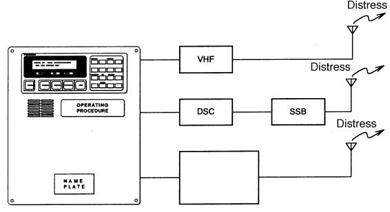
Peripheral Equipment
The following equipment can be additionally connected to the FELCOM 15.
Distress Message Controller (DMC-5)
The DMC-5 provides for transmission and monitoring of the distress alert. For further details, refer to the operator’s manual of the DMC-5.
Inmarsat C
FELCOM 15
Distress Message Controller DMC-5
Distress message controller system
xiv

1.OPERATIONAL OVERVIEW
1.1Terminal Unit
The terminal unit is the heart of the FELCOM 15 system, creating, transmitting and receiving messages.
Floppy disk |
POWER |
drive |
switch |
|
DISTRESS |
|
button |
|
Terminal unit IC-215 |
1.1.1Turning the power on/off
Press the [POWER] switch to power or turn off the terminal unit, antenna unit, Distress Alert/Received Call Unit and Alarm Unit.
Note: The example screens shown in this manual may not match the screens you see on your display. The screen you see depends on your system configuration and equipment settings.
1.1.2DISTRESS button
Use the [DISTRESS] button to transmit the distress alert when there is a life-endangering situation on your ship.
1.1.3Diagnostics
When the terminal unit is turned on it automatically checks itself for proper operation. For detailed information, see Chapter 8.
1-1
1. OPERATIONAL OVERVIEW
1.1.4Floppy disk drive, floppy disks
The terminal unit provides a floppy disk drive for storing transmitted and received messages on floppy disks. The floppy disks used with the system are 2HD (1.44 MB) and 2DD (720 KB).
1.1.5Audio alarm
The audio alarm is released in the following instances.
Unit |
Telex, |
Distress |
EGC message received |
Trouble |
||
|
acknowledge |
Distress |
Urgency |
Other |
detected |
|
|
received |
received |
|
|
|
|
Terminal Unit |
YES |
YES |
YES |
YES |
NO |
YES |
Distress |
NO |
YES |
YES |
YES |
NO |
NO |
Alert/Received |
|
|
|
|
|
|
Call Unit |
|
|
|
|
|
|
Alarm Unit |
YES |
NO |
NO |
NO |
NO |
YES |
Distress |
NO |
YES |
YES |
YES |
NO |
NO |
Message |
|
|
|
|
|
|
Controller |
|
|
|
|
|
|
1.1.6Adjusting brilliance
Raising brilliance: Press [Alt] + [F7].
Lowering brilliance: Press [Alt] + [F6].
1-2
1. OPERATIONAL OVERVIEW
1.2Keyboard
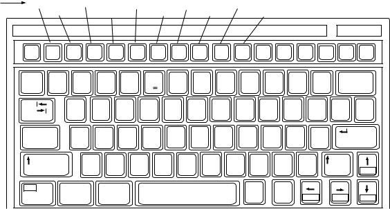
The FELCOM 15 is almost 100% keyboard controlled. Operation is carried out with the function keys, numbered F1-F10 at the top of the keyboard. The figure below shows keyboard layout.
Function |
File |
|
|
Transmit |
Reports |
Options |
|
Position |
|
|
|
|
|
|
|
||||||
Keys |
|
|
Edit |
EGC |
|
Logs |
Setup |
|
StopAlarm |
|
|
|
|
||||||||
|
Esc |
F1 |
F2 |
F3 |
F4 |
F5 |
F6 |
F7 |
F8 |
F9 |
|
F10 |
|
Num |
Prt Sc |
|
Scroll |
|
Pause Insert |
Delete |
|
|
|
|
Lock |
SysRq |
|
Lock |
|
Break |
|
||||||||||||
|
|
|
|
|
|
|
|
|
|
|
|
|
|
|
|
|
|
|
|||
|
~ |
|
! |
@ |
# |
$ |
|
% |
^ |
& 7 |
* |
8 |
( |
9 |
) |
* |
_ |
|
+ |
Backspace |
|
|
` |
|
1 |
2 |
3 |
4 |
|
5 C |
6 |
7 |
8 |
|
9 |
|
0 |
|
- |
|
= |
|
|
|
Tab |
|
|
Q |
W |
E |
|
R |
T |
Y |
U |
4 |
I |
5 |
O 6 |
P |
|
|
{ |
} |
| |
|
|
|
|
|
|
|
|
|
|
|
|
|
|
|
|
|
|
|
[ |
] |
\ |
|
Caps Lock |
|
A |
S |
D |
|
F |
G |
H |
J |
1 |
K 2 |
L |
3 |
: |
+ |
" |
Enter |
|||
|
|
|
|
|
|
|
|
|
|
|
|
|
|
|
|
; |
|
' |
|
|
|
|
Shift |
|
|
Z |
|
X |
C |
V |
B |
N |
|
M 0 |
< |
> |
|
? |
/ |
Shift |
|
||
|
|
|
|
|
|
|
|
|
|
|
|
|
|
, |
|
. |
|
/ |
|
|
PgUp |
|
Fn |
|
|
Ctrl |
Alt |
|
|
|
|
|
|
|
|
Alt |
|
Ctrl |
|
|
|
|
|
|
|
|
|
|
|
|
|
|
|
|
|
|
|
|
|
|
|
Home |
End |
PgDn |
|
Keyboard
1.2.1Key description
Esc |
Cancels key input and returns to previous display |
F1-F10 |
screen. |
These are the function keys, and they choose |
|
Backspace |
menus. |
Deletes the character to the left of the cursor. |
|
Insert |
Works the same as “paste.” See “Copying and |
Delete |
pasting text” in paragraph 3.2.4. |
Deletes the character selected with the cursor. |
|
Home |
Moves the cursor to the top of the message being |
End |
edited. |
Moves the cursor to the bottom of the message |
|
PgUp |
being edited. |
Goes to the previous page of the edit screen. |
|
PgDn |
Goes to the next page of the edit screen. |
[↑ ], [↓ ], [← ], [→ ] |
Control the cursor. |
Enter |
Registers key input; inserts carriage return in TX |
Shift |
message. |
Chooses upper or lower case alphabet. Press and |
|
|
hold down the key and then press the [Caps Lock] to |
|
get upper or lower case alphabet. Note that only |
Alt |
upper case alphabet are used in telex. |
Executes the shortcut key operation when combined |
|
|
with an alphabet key. See paragraph 1.2.2. |
1-3

1. OPERATIONAL OVERVIEW |
|
Space |
Inserts a space. In addition, it displays the file list, a |
Caps Lock |
partial view of a file, etc., depending on menu. |
Turns upper case alphabet input on or off. The Caps |
|
|
Lock LED lights when upper case alphabet input is |
Tab |
on. |
Inserts horizontal tab characters. The number of tab |
|
|
characters the key can insert per line of text can be |
Ctrl |
programmed for two, four or eight tabs. |
Works in combination with alphabet keys as follows: |
|
|
Ctrl + [M]: Same as Enter. |
|
Ctrl + [H]: Same As Back Space. |
|
Ctrl + [I]: Same as Insert. |
|
Ctrl + [V]: Same as Overwrite+Insert on Edit Mode in |
Fn |
the Editor Setup menu. |
Combined with an arrow key, it scrolls screen (↑ , ↓ ), |
|
Num Lock |
or shifts cursor (← , → ). |
Turns numeric input on or off. Note that you cannot |
|
|
enter alphabet when the Num Lock LED is lit. |
Note 1: In telex, lower case, #, &, *, $, @, %, etc. are not used. A full list of characters useable in telex appears in the Appendix. For e-mail all characters and symbols may be used.
Note 2: € (Euro mark) on the 5% C key cannot be used.
1-4
1. OPERATIONAL OVERVIEW
1.2.2Shortcut keys
The FELCOM 15 provides the keyboard shortcuts shown below for commonly used functions.
|
Shortcut keys |
|
|
Shortcut key |
Function |
[Alt]+[N] |
Same as New in File menu |
[Alt]+[O] |
Same as Open in File menu |
[Alt]+[Q] |
Same as Close in File menu |
[Alt]+[D] |
Same as Delete in File menu |
[Alt]+[S] |
Same as Save in File menu |
[Alt]+[P] |
Same as Print in File menu |
[Alt]+[X] |
Same as Undo |
[Delete] |
Same as Cut in Edit menu |
[Alt]+[C] |
Same as Copy in Edit menu |
[Insert] |
Same as Paste in Edit menu |
[Fn] + ← |
Same as Top of Text in Edit menu |
[Fn] + → |
Same as End of Text in Edit menu |
[Alt]+[V] |
Same as Change Window in Edit menu |
1.2.3Function key description
|
Function key description |
|
|
Menu |
Description |
File (F1) |
Processes files. |
Edit (F2) |
Provides text editing facilities. |
Transmit (F3) |
Transmits messages. |
EGC (F4) |
Sets up EGC message facilities. |
Reports (F5) |
Sets up data/message reporting function. |
Logs (F6) |
Displays sent and received message logs. |
Options (F7) |
Login, logout; testing facilities. |
Setup (F8) |
Sets up the system. |
Position (F9) |
Enter your ship’s position manually. |
StopAlarm (F10) |
Silences audio alarm. |
1-5
1. OPERATIONAL OVERVIEW
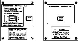
1.3Distress Alert/Received Call Unit IC-305, Alarm Unit IC-306
Distress Alert/Received Call Unit IC-305
The [DISTRESS] button functions to transmit the distress alert. To transmit the distress alert, press the button until its lamp lights continuously. For further details on how to transmit the distress alert, see paragraph 6.1.
The IC-305 releases the audio alarm and the lamp in the [ALARM ACK] button flashes when an EGC distress or urgency broadcast is received. Press the [ALARM ACK] button to acknowledge the alarm, and the alarm tone changes. To silence the alarm and extinguish the lamp, press the function key F10 on the keyboard of the terminal unit.
Alarm Unit IC-306
The IC-306 releases the audio alarm and flashes the lamp in its [ALARM RESET] button when a telex or e-mail is received. To silence the audio alarm in this case, press the [ALARM RESET] button on the IC-306. In addition to telex or e-mail notification, the audio alarm sounds and the lamp flashes also for the equipment trouble listed below. To acknowledge this alarm, press the [ALARM RESET] button, and the alarm tone changes. To silence the alarm and flashing of the button in case of external equipment abnormality, press the [F10] key on the keyboard.
•“Unsync” condition (MES is not synchronized with satellite) continues for six minutes. (UNSYNC appears at the bottom of the screen.)
•BBER is over 80% (BBER of 080 or higher appears on the system status monitor.)
Note: The equipment cannot scan automatically in the above two situations. Reselect ocean region referring to paragraph 7.2.
•Printer has no paper
•No data is received from internal or external GPS navigator
•Update position alert (manual position input) when position has not been updated for four hours.
•Equipment trouble (synthesizer, oscillator, etc.)
MES ALARMS AND
INCOMING MESSAGES
ACK
ALARM UNIT
I 
Distress Alert/Received Call Unit |
Alarm Unit |
IC-305 |
IC-306 |
Distress Alert/Received Call Unit IC-305, Alarm Unit IC-306
1-6
1. OPERATIONAL OVERVIEW
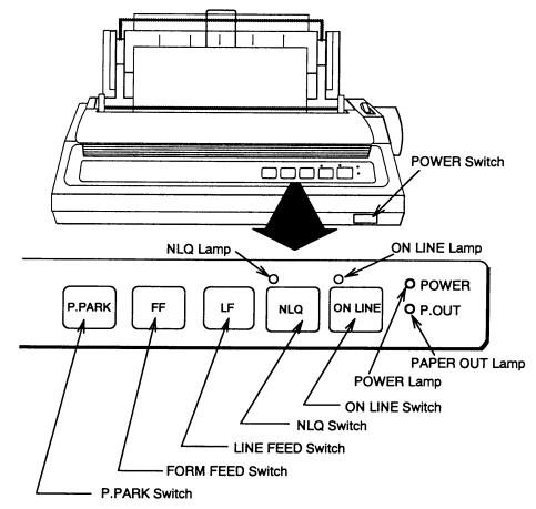
1.4Printer PP-510 (option)
The PP-510 prints transmitted and received messages. The POWER switch is on the right side of the unit. The lamp on the switch lights when the power is on. If the paper is set correctly the ON LINE lamp also lights. When both those lamps are lit, the printer is ready to print information received from the terminal unit. For further details, refer to the PP-510’s operator’s manual.
Printer PP-510
1-7

1. OPERATIONAL OVERVIEW
1.5Standby Display
After the equipment is turned on and the diagnostic test has been conducted, the standby display appears, showing the system status monitor. The system status monitor provides various operating information. For a detailed description, see paragraph 8.4.
|
File Edit Transmit |
EGC |
Reports Logs |
Options Setup |
Position |
StopAlarm |
||
|
|
|
|
|
|
|
||
|
|
|
|
|
IMN: |
443156710 |
||
|
Date |
02-02-25 |
|
BBER |
|
000 |
|
|
|
Time |
01:32 (UTC) |
C/N |
|
OK ( |
0 dB) |
||
|
|
|
|
Send Level |
|
OK ( |
0) |
|
|
Position |
LAT 34:30.00N |
Rx AGC Level |
|
OK (254) |
|||
|
|
LON 135:00.00E |
REF Offset Freq |
|
OK ( |
0 Hz) |
||
|
Waypoint |
LAT |
|
Synthe Local |
|
OK |
|
|
|
|
LON |
|
VCXO Control |
131 |
|
|
|
|
Course |
345.5 DEG |
|
|
|
|
|
|
|
Speed |
10.2 KTS |
|
|
|
|
|
|
|
Current NCS |
344 (IOR) |
LOGOUT |
Antenna Power Supply |
OK |
|
|
|
|
Current Channel |
NCS CC |
|
|
|
|
|
|
|
Current TDM |
NCS CC |
|
Water Temperature |
|
68.2 DEG |
||
|
MES Status |
Idle |
|
Water Current |
|
|
|
|
|
GPS Status |
**** |
|
Direction |
|
232 |
DEG |
|
|
|
|
|
Speed |
|
1.9 |
KTS |
|
|
DCE Memory |
32818 Bytes free |
Depth |
|
|
|
|
|
|
|
|
|
|
||||
|
Current State: IDLE |
|
Retuning |
02-02-25 01:32 (UTC) |
||||
|
|
|
NCS: IOR |
LOGOUT |
LAT: 34:30.00N |
|||
|
DCE F15 Ver. ## |
|
|
|
LON: 135:00.00E |
|||
|
|
|
|
|
|
|
|
|
##: Program Version No. of RF CON Board
Standby display
After the diagnostic test has been completed, the equipment automatically starts synchronizing itself with a satellite. When the indication “Retuning” is replaced with “ SYNC(NCS), the synchronization process is completed. Then, you are ready to receiving EGC messages. For further details see paragraph 2.4.
Note: When the caution shown below appears, it is necessary to change the LES ID in the distress alert setup to match current ocean region. For further details, see paragraph 6.2.
CAUTION
Pre-set LES ID for DISTRESS ALERT is invalid in the present ocean region.
Please input preferred LES ID in the [Distress Alert Setup] menu.
1-8

1. OPERATIONAL OVERVIEW
1.5.1Display indications
The display is divided in three sections:
1)The function menu area
2)The working area
3)The operating status area
|
File Edit Transmit EGC |
Reports Logs Options Setup Position StopAlarm |
|
|
|
|
|
1) Function |
||
|
|
|
|
|
|
|||||
|
(1) |
|
|
(2) |
|
|
|
|
|
Menu |
|
|
|
|
|
|
|
|
|||
|
|
|
|
|
|
|
|
|
|
|
2) WORKING AREA
 3) Operating
Status
(3) |
|
(5) |
|
|
|
|
(9) |
|
||
(4a) |
|
|
(6) |
|
|
(7) |
|
|
(10) |
|
(4b) |
|
|
(8) |
|
|
|
|
|
(10) |
|
|
|
|
|
|
||||||
|
|
|
|
|
|
|
|
|
|
|
Location of display indications
Below are the indications and meanings of the items in parentheses in the illustration above.
(1) Distress alert information message
No display (no distress alert)
Sending Distress Alert
Sending Distress Alert Test
Distress Acknowledgement Received
Distress Message Call Activated
Distress Message Call Acknowledged
Distress Button Test Mode
(2) Communication network mode
No display |
Normal operation |
Restoration Mode |
Problem at NCS |
(Flashing) |
|
Restoration Mode |
Previously designated LES is transmitting the |
(Reverse video) |
NCS common channel signal. |
1-9
1. OPERATIONAL OVERVIEW |
|
|
(3) Terminal unit status |
|
|
IDLE |
Idle (awaiting receiving, awaiting transmitting) |
|
IDLE (PENDING) |
Awaiting reply from LES |
|
SENDING |
Sending |
|
RECEIVING |
Receiving |
|
LOGIN |
Logged in with NCS |
|
LOGOUT |
Logging out with NCS |
|
DISTRESS ALERT |
When own vessel is transmitting the distress alert |
|
Data Report |
Sending data report |
|
TESTING |
Performance Verification (PV) testing |
|
TEST SETUP |
Requesting PV testing |
|
SCANNING |
NCS scanning |
|
EGC RECEIVER |
EGC-only receiver operation |
|
(Reverse video) |
|
|
Delivery Status Req. |
Transmitting delivery status request |
|
Forced Clearing |
Stopping receiving, transmitting, or scanning |
|
(4a) Communication status |
|
|
CALLING |
|
Now calling |
WAITING FOR ACKNOWLEDGEMENT Waiting for acknowledgement from |
||
|
|
LES. |
RECEIVING EGC MESSAGE |
Now receiving EGC message |
|
WAITING FOR BACKOFF |
|
Waiting to transmit data report |
Successful Login. |
|
Login was successful |
Login failed. |
|
Login failed |
Successful Logout |
|
Logout was successful |
Logout failed. |
|
Logout failed |
Successful Distress Alert. |
|
Distress alert successfully |
Distress Alert Failed |
|
Distress alert could not be transmitted. |
Successful Forced Clearing. |
Forced clearing successful |
|
Forced Clearing Failed. |
|
Forced clearing unsuccessful |
SENDING MESSAGE PACKETS. |
Sending TX message packets |
|
WAITING FOR ACKNOWLEDGEMENT Waiting for acknowledgement from LES |
||
Successful sending to LES. |
|
Message successfully sent to LES |
Sending message failed. |
|
Message could not be sent to LES |
Call rejected. |
|
LES rejected your message |
Call pending. |
|
LES temporarily suspending |
|
|
communications |
Received Call. |
|
Call received from LES |
Received Call(ITA2). |
|
Call(ITA2) received from LES |
RECEIVING MESSAGE PACKETS |
Receiving message packets |
|
CLEARING |
|
Clearing TX sequence |
Successful receiving. |
|
You successfully received message |
Receiving failed. |
|
You could not receive message |
Successful Data Report. |
|
Data report successfully sent. |
Data Report failure. |
|
Data report could not be sent. |
PV TEST CALL is rejected. |
|
PV test call rejected by NCS |
1-10
|
1. OPERATIONAL OVERVIEW |
PV TEST CALL is pending. |
PV test pending by LES |
TEST-RECEIVING MESSAGE |
Receiving test message from LES |
TEST-SENDING MESSAGE |
Sending test message to LES |
TEST-DISTRESS ALERT |
Sending test distress alert to LES |
WAITING FOR ACTIVATION |
Waiting start of PV test |
WAITING FOR TEST RESULT |
Waiting for results of PV test |
CLEARING |
Clearing PV test |
PV TEST is Completed. |
PV test is completed. |
PV TEST Failure. |
PV test failed. |
(4b) RF CON/CPU’s program version number
DCE F15 Ver. XX (XX = Version Number)
Note: Error message is displayed when equipment abnormality is detected.
(5) Frame synchronization
Blank |
Changing channel, or during transmission |
SYNC (NCS) |
Synchronizing with NCS |
SYNC (LES) |
Synchronizing with LES |
MES Sig. Ch |
Changing MES signaling channel |
MES Msg. Ch |
Changing MES message channel |
UNSYNC |
Out of synchronization |
Retuning |
Synchronizing with NCS or LES |
(6) Ocean region receiving |
|
No display |
Out of synch with satellite |
AOR-W |
Atlantic Ocean Region-West |
AOR-E |
Atlantic Ocean Region-East |
IOR |
Indian Ocean Region |
POR |
Pacific Ocean Region |
(7) Logging status |
|
LOGOUT |
Logged out with ocean region |
LOGIN |
Logged in with ocean region |
LOGIN (Flashing) |
Logging in with ocean region |
1-11
1. OPERATIONAL OVERVIEW |
|
(8) Other information |
|
No display |
No receive message in memory, or printer is |
|
operating. |
REC. MESSAGE EXISTS |
Displayed when a routine message has |
(Reverse video) |
not been printed, or a confidential message is |
|
received. |
Data Report |
When data reporting is activated. |
(Reverse video) |
|
Message Report |
Message report setting is activated. |
(Reverse video) |
|
(9) Date and time display
With connection of a navigator (internal GPS navigator or external navigator), date and time (received from satellite) are displayed. Manually input date and time are also displayed.
(10) Ship’s position
With connection of a navigator (internal GPS navigator or external navigator), ships position is displayed in latitude and longitude and updated every 30 seconds, or manually input position is displayed.
1-12

1. OPERATIONAL OVERVIEW
1.6Menu Overview
Operation of the FELCOM 15 is carried out through a menu system which you access with the function keys at the top of the screen. The example below shows how to choose menu options from the Editor Setup menu.
1. Press the [F8] key to display the Setup menu.
File Edit Transmit EGC |
Reports Logs Options |
Setup |
Position StopAlarm |
|
|
|
|
Setup
1.Distress Alert Setup
2.System Setup
3.Editor Setup
4.Terminal Setup
5.EGC Setup
6.Auto Mode Setup
7.E-Mail Setup
8.Directories
9.Configuration
Setup menu
2.Choose desired menu by pressing appropriate numeric key. For example, press the [3] key to show the Editor Setup menu.
Note: You may also choose a menu with the [↑ ] and [↓ ] keys, pressing [Enter] after making selection.
File Edit Transmit EGC |
Reports Logs Options |
Setup |
Position StopAlarm |
||||||||
|
|
|
|
|
|
|
|
|
|
|
|
|
|
|
|
Setup |
|
|
|
|
|
|
|
|
|
|
|
|
|
|
|
|
|
||
|
|
|
Editor Setup |
|
|
|
|
|
|
||
|
|
|
|
|
|
|
|
|
|||
|
|
2.TextSys emModeSetup |
Ascii |
|
|
|
|
|
|||
|
|
3.EditorModeSetup |
Insert |
|
|
|
|
|
|||
4.WordTerminalWrapSetup ON
5.LineEGCNoSetup. ON
6.TabAutoWidthMode Setup4 Char
7.ColumnE-Mail SetupWidth 69
8.CuDirsorectoriesType |
Block |
9.ScrollConfiguration |
Full Screen |
Editor setup menu
3.Choose desired menu item by pressing the [↑ ] or [↓ ] keys followed by the [Enter] key. A window displaying the options for the item selected or an alphanumeric data entry window appears depending on your selection. For example, choose Word Wrap.
ON
OFF
Word wrap options window
1-13

1.OPERATIONAL OVERVIEW
4.Press the [↓ ] or [↑ ] key to choose option desired and press the [Enter] key.
5.Press the [Esc] key several times to return to the standby display.
Note: On some menus the update window appears after you press the [Esc] key. This is done to ask you to confirm settings. Yes is selected; press the [Enter] key to register settings, or press [→ ] to choose No and press the [Enter] key to escape.
Update
Yes No
1.7Error Messages and Alerts
The terminal unit displays error messages and alerts, in the CAUTION window, to call your attention to misoperation, failed operation and system error. A list of error messages appears in Chapter 8 and alerts appear in the Appendix.
To erase an error message or alert, press the [Esc] key.
File Edit Transmit EGC |
Reports |
Logs |
Options Setup Position StopAlarm |
|
|
|
|
Log
1.Send Message Log
2.Receive Message Log
Send Message Log
No. Message File Station |
LES |
Priority Send Status |
Delivery |
CAUTION
No Message.
<Press ESC key to continue>
Location of error messages and alerts
1-14
 Loading...