


 Loading...

IMPORTANT NOTICES
General
•This manual has been authored with simplified grammar, to meet the needs of international users.
•The operator of this equipment must read and follow the descriptions in this manual. Wrong operation or maintenance can cancel the warranty or cause injury.
•Do not copy any part of this manual without written permission from FURUNO.
•If this manual is lost or worn, contact your dealer about replacement.
•The contents of this manual and equipment specifications can change without notice.
•The example screens (or illustrations) shown in this manual can be different from the screens you see on your display. The screens you see depend on your system configuration and equipment settings.
•Save this manual for future reference.
•Any modification of the equipment (including software) by persons not authorized by FURUNO will cancel the warranty.
•All brand and product names are trademarks, registered trademarks or service marks of their respective holders.
•“C- MAP” means “C-MAP by Jeppesen” in this manual.
How to discard this product
Discard this product according to local regulations for the disposal of industrial waste. For disposal in the USA, see the homepage of the Electronics Industries Alliance (http://www.eiae.org/) for the correct method of disposal.
How to discard a used battery
Some FURUNO products have a battery(ies). To see if your product has a battery, see the chapter on Maintenance. Follow the instructions below if a battery is used. Tape the + and - terminals of battery before disposal to prevent fire, heat generation caused by short circuit.
In the European Union
The crossed-out trash can symbol indicates that all types of |
|
|
|
batteries must not be discarded in standard trash, or at a trash |
|
|
|
site. Take the used batteries to a battery collection site |
|
|
|
according to your national legislation and the Batteries Directive |
|
Cd |
|
2006/66/EU. |
|
||
|
|
||
In the USA |
|
|
|
The Mobius loop symbol (three chasing arrows) indicates that |
|
|
|
Ni-Cd and lead-acid rechargeable batteries must be recycled. |
|
|
|
Take the used batteries to a battery collection site according to |
Ni-Cd |
Pb |
|
local laws. |
|||
|
|
In the other countries
There are no international standards for the battery recycle symbol. The number of symbols can increase when the other countries make their own recycling symbols in the future.
i

SAFETY INSTRUCTIONS

 SAFETY INSTRUCTIONS
 WARNING
ELECTRICAL SHOCK HAZARD
Do not open the equipment.
Only qualified personnel should work inside the equipment.
Turn off the radar power switch before servicing the antenna unit. Post a warning sign near the switch indicating it should not be turned on while the antenna unit is being serviced.
Prevent the potential risk of being struck by the rotating antenna and exposure to RF radiation hazard.
Wear a safety belt and hard hat when working on the antenna unit.
Serious injury or death can result if someone falls from the radar antenna mast.
Do not disassemble or modify the equipment.
Fire, electrical shock or serious injury can result.
Turn off the power immediately if water leaks into the equipment or the equipment is emitting smoke or fire.
Continued use of the equipment can cause fire or electrical shock.
Use the proper fuse.
Fuse rating is shown on the power cable. Use of a wrong fuse can result in damage to the equipment.
Keep heater away from equipment.
Heat can alter equipment shape and melt the power cord, which can cause fire or electrical shock.
 WARNING
Radio Frequency
Radiation Hazard
The radar antenna emits electromagnetic radio frequency (RF) energy which can be harmful, particularly to your eyes. Never look directly into the antenna aperture from a close distance while the radar is in operation or expose yourself to the transmitting antenna at a close distance.
Distances at which RF radiation levels of 100 and 10 W/m2 exist are given in the table below.
Note: If the antenna unit is installed at a close distance in front of the wheel house, your administration may require halt of transmission within a certain sector of antenna revolution. This is possible - Ask your FURUNO representative or dealer to provide this feature.
|
|
Distance to |
Distance to |
|
MODEL |
100 W/m2 |
10 W/m2 |
||
|
|
point |
point |
|
|
|
|
|
|
MODEL |
Nil |
Worst case |
||
1824C |
0.70 m |
|||
|
||||
|
|
|
||
MODEL |
Nil |
Worst case |
||
1834C |
1.50 m |
|||
|
||||
|
|
|
|
|
MODEL |
Worst case |
Worst case |
||
1934C |
0.10 m |
1.70 m |
||
|
|
|
|
|
MODEL |
Nil |
Worst case |
||
1944C |
1.20 m |
|||
|
||||
|
|
|
|
|
MODEL |
XN-12A |
0.20 m |
Worst case 2.00 m |
|
1954C |
|
|
|
|
XN-13A |
Nil |
Worst case 1.40 m |
||
|
||||
MODEL |
XN-12A |
0.50 m |
Worst case 5.40 m |
|
1964C |
XN-13A |
0.40 m |
Worst case 3.60 m |
|
|
|
|
|
|
Warning Label
A warning label is attached to the equipment. Do not remove the label. If the label is missing or damaged, contact a FURUNO agent or dealer.
WARNING |
Name: Warning Label (1) |
|
Type: 86-003-1011-0 |
||
To avoid electrical shock, do not |
||
remove cover. No user-serviceable |
Code No.: 100-236-230 |
|
parts inside. |
|
ii
TABLE OF CONTENTS
|
|
|
|
|
FOREWORD |
...................................................................................................... |
viii |
||
SYSTEM CONFIGURATIONS .............................................................................. |
x |
|||
1. |
OPERATIONAL OVERVIEW ....................................................................... |
1-1 |
||
|
1.1 |
Operating Controls ............................................................................................................. |
1-1 |
|
|
1.2 |
Inserting a Chart Card........................................................................................................ |
1-3 |
|
|
1.3 |
Turning the Unit On/Off ...................................................................................................... |
1-4 |
|
|
1.4 |
Display Brilliance, Panel Brilliance, Hue............................................................................. |
1-5 |
|
|
|
1.4.1 Display brilliance, panel brilliance .......................................................................... |
1-5 |
|
|
|
1.4.2 |
Hue ........................................................................................................................ |
1-6 |
|
1.5 |
Selecting a Display............................................................................................................. |
1-7 |
|
|
|
1.5.1 |
Display modes ....................................................................................................... |
1-7 |
|
|
1.5.2 |
Selecting a display ................................................................................................. |
1-8 |
|
|
1.5.3 Switching control in combination and overlay screens ........................................... |
1-9 |
|
|
|
1.5.4 |
Selecting image source........................................................................................ |
1-10 |
|
1.6 |
Trackball, Cursor.............................................................................................................. |
1-11 |
|
|
1.7 |
Entering the MOB Mark, Setting MOB as Destination...................................................... |
1-12 |
|
|
1.8 |
Data Boxes....................................................................................................................... |
1-13 |
|
|
|
1.8.1 Showing, hiding data boxes with soft key............................................................. |
1-13 |
|
|
|
1.8.2 |
Rearranging data boxes....................................................................................... |
1-13 |
|
|
1.8.3 Temporarily erasing a data box ............................................................................ |
1-13 |
|
|
1.9 |
Function Keys .................................................................................................................. |
1-14 |
|
|
1.10 |
Simulation Display............................................................................................................ |
1-15 |
|
2. |
RADAR OPERATION .................................................................................. |
2-1 |
||
|
2.1 |
Radar Display..................................................................................................................... |
2-1 |
|
|
2.2 |
Transmitting, Stand-by ....................................................................................................... |
2-1 |
|
|
2.3 |
Tuning ................................................................................................................................ |
|
2-2 |
|
2.4 |
Adjusting the Gain.............................................................................................................. |
2-2 |
|
|
2.5 |
Reducing Sea Clutter ......................................................................................................... |
2-3 |
|
|
|
2.5.1 |
How the A/C SEA works......................................................................................... |
2-3 |
|
|
2.5.2 |
Adjusting the A/C SEA ........................................................................................... |
2-4 |
|
2.6 |
Reducing Precipitation Clutter............................................................................................ |
2-4 |
|
|
|
2.6.1 |
Adjusting the A/C RAIN.......................................................................................... |
2-4 |
|
2.7 |
Range Scale ...................................................................................................................... |
2-5 |
|
|
2.8 |
Pulselength ........................................................................................................................ |
2-5 |
|
|
2.9 |
Presentation Mode ............................................................................................................. |
2-6 |
|
|
|
2.9.1 Selecting a presentation mode............................................................................... |
2-6 |
|
|
|
2.9.2 Description of presentation modes......................................................................... |
2-7 |
|
|
2.10 Measuring the Range......................................................................................................... |
2-8 |
||
|
|
2.10.1 |
Measuring range by range rings ............................................................................ |
2-8 |
|
|
2.10.2 |
Measuring range by cursor .................................................................................... |
2-8 |
|
|
2.10.3 |
Measuring range by VRM ...................................................................................... |
2-9 |
|
|
2.10.4 Various VRM operations.......................................................................................... |
2-9 |
|
|
2.11 |
Measuring the Bearing ..................................................................................................... |
2-10 |
|
|
|
2.11.1 Measuring bearing by cursor................................................................................ |
2-10 |
|
|
|
2.11.2 Measuring bearing by EBL................................................................................... |
2-10 |
|
|
|
2.11.3 Various EBL operations ......................................................................................... |
2-10 |
|
iii
TABLE OF CONTENTS |
|
||
2.12 |
Erasing the Heading Line, North Marker.......................................................................... |
2-11 |
|
2.13 |
Reducing Noise Interference............................................................................................ |
2-11 |
|
2.14 |
Rejecting Radar Interference ........................................................................................... |
2-11 |
|
2.15 |
Zoom................................................................................................................................ |
|
2-12 |
|
2.15.1 |
Zooming radar targets.......................................................................................... |
2-12 |
|
2.15.2 |
Zooming ARP, TTM targets .................................................................................. |
2-13 |
2.16 |
Shifting the Picture........................................................................................................... |
2-14 |
|
|
2.16.1 |
Manual shift.......................................................................................................... |
2-14 |
|
2.16.2 |
Automatic shift ..................................................................................................... |
2-14 |
2.17 |
Using the Offset EBL ....................................................................................................... |
2-15 |
|
|
2.17.1 |
Predicting collision course ................................................................................... |
2-15 |
|
2.17.2 |
Measuring range & bearing between two targets................................................. |
2-16 |
2.18 |
Echo Trails ....................................................................................................................... |
2-17 |
|
|
2.18.1 |
Trail time .............................................................................................................. |
2-17 |
|
2.18.2 |
Starting echo trails ............................................................................................... |
2-18 |
|
2.18.3 |
Trail gradation ...................................................................................................... |
2-18 |
|
2.18.4 |
Trail color ............................................................................................................. |
2-18 |
|
2.18.5 |
Echo trail mode.................................................................................................... |
2-19 |
2.19 |
Echo Stretch .................................................................................................................... |
2-19 |
|
2.20 |
Echo Averaging................................................................................................................ |
2-20 |
|
2.21 |
Outputting TLL Data......................................................................................................... |
2-21 |
|
2.22 |
Guard Alarm..................................................................................................................... |
2-22 |
|
|
2.22.1 |
Setting a guard alarm zone.................................................................................. |
2-22 |
|
2.22.2 |
When the alarm is violated… ............................................................................... |
2-23 |
|
2.22.3 |
Cancelling the guard alarm .................................................................................. |
2-23 |
2.23 |
Watchman........................................................................................................................ |
2-23 |
|
|
2.23.1 |
How watchman works .......................................................................................... |
2-23 |
|
2.23.2 |
Turning on/off watchman...................................................................................... |
2-23 |
|
2.23.3 |
Setting watchman stand-by interval ..................................................................... |
2-24 |
2.24 |
Suppressing Second-trace Echoes.................................................................................. |
2-24 |
|
2.25 |
Waypoint Marker.............................................................................................................. |
2-25 |
|
2.26 |
ARP, TTM Operation ........................................................................................................ |
2-26 |
|
|
2.26.1 |
Activating/deactivating ARP, TTM ........................................................................ |
2-27 |
|
2.26.2 |
Acquiring and tracking targets (ARP)................................................................... |
2-27 |
|
2.26.3 |
Displaying target number (ARP, TTM).................................................................. |
2-29 |
|
2.26.4 |
Terminating tracking of ARP targets..................................................................... |
2-29 |
|
2.26.5 |
Setting vector attributes (ARP) ............................................................................ |
2-30 |
|
2.26.6 |
Displaying past position (ARP)............................................................................. |
2-31 |
|
2.26.7 |
ARP, TTM target data........................................................................................... |
2-31 |
|
2.26.8 |
CPA/TCPA alarm (ARP)....................................................................................... |
2-32 |
|
2.26.9 |
Lost target alarm (ARP) ....................................................................................... |
2-33 |
2.27 |
Interpreting the Radar Display ......................................................................................... |
2-34 |
|
|
2.27.1 |
False echoes ....................................................................................................... |
2-34 |
|
2.27.2 |
SART (Search and Rescue Transponder)............................................................ |
2-35 |
|
2.27.3 |
Racon (Radar Beacon) ........................................................................................ |
2-36 |
3. PLOTTER OPERATION .............................................................................. |
3-1 |
||
3.1 |
Plotter Displays .................................................................................................................. |
3-1 |
|
|
3.1.1 |
Full-screen plotter display ...................................................................................... |
3-1 |
|
3.1.2 |
Nav graphic display................................................................................................ |
3-3 |
|
3.1.3 |
Highway display..................................................................................................... |
3-6 |
|
3.1.4 |
Nav data display .................................................................................................... |
3-7 |
3.2 |
Presentation Mode............................................................................................................. |
3-8 |
|
3.3 |
Shifting the Display ............................................................................................................ |
3-9 |
|
3.4 |
Chart Scale ........................................................................................................................ |
3-9 |
|
iv
3.5 |
Chart Cards ........................................................................................................................ |
3-9 |
|
|
3.5.1 |
Chart card overview ......................................................................................... |
3-9 |
|
3.5.2 |
Indices and chart enlargement ....................................................................... |
3-10 |
|
3.5.3 |
Navionics charts ............................................................................................. |
3-11 |
|
3.5.4 |
C - MAP by Jeppesen charts ........................................................................... |
3-14 |
3.6 |
Working with Track ........................................................................................................... |
3-18 |
|
|
3.6.1 |
Displaying track ............................................................................................. |
3-18 |
|
3.6.2 |
Stopping, restarting plotting of own ship track ............................................... |
3-19 |
|
3.6.3 |
Changing track color ...................................................................................... |
3-19 |
|
3.6.4 |
Track plotting method and interval for own ship track .................................... |
3-20 |
|
3.6.5 |
Changing own ship track/mark distribution setting ......................................... |
3-21 |
|
3.6.6 |
Erasing track .................................................................................................. |
3-22 |
3.7 |
Marks, Lines ..................................................................................................................... |
3-23 |
|
|
3.7.1 |
Entering a mark, line ...................................................................................... |
3-23 |
|
3.7.2 |
Changing mark attributes ............................................................................... |
3-24 |
|
3.7.3 |
Selecting line type .......................................................................................... |
3-24 |
|
3.7.4 |
Erasing marks, lines ....................................................................................... |
3-25 |
3.8 |
Waypoints......................................................................................................................... |
3-26 |
|
|
3.8.1 |
Entering waypoints ......................................................................................... |
3-26 |
|
3.8.2 |
Editing waypoint data ..................................................................................... |
3-29 |
|
3.8.3 |
Erasing waypoints .......................................................................................... |
3-30 |
|
3.8.4 |
Changing waypoint mark size (Navionics GOLD) .......................................... |
3-31 |
|
3.8.5 |
Searching waypoints ...................................................................................... |
3-32 |
3.9 |
Routes |
.............................................................................................................................. |
3-33 |
|
3.9.1 .............................................................................................. |
Creating routes |
3-33 |
|
3.9.2 .......................................................................................... |
Connecting routes |
3-36 |
|
3.9.3 ........................................................................................ |
Inserting waypoints |
3-37 |
|
3.9.4 ................................................................. |
Removing waypoints from a route |
3-38 |
|
3.9.5 ................................................................................................ |
Erasing routes |
3-39 |
3.10 Navigation ........................................................................................................................ |
3-39 |
||
|
3.10.1 ..........................................................................Navigating to a “quick point” |
3-39 |
|
|
3.10.2 .................................................................................Navigating to waypoints |
3-40 |
|
|
3.10.3 ........................................Navigating to ports, port services (NavChart only) |
3-41 |
|
|
3.10.4 ...........................................................................................Following a route |
3-43 |
|
|
3.10.5 ..............................................................................Cancelling route navigtion |
3-46 |
|
3.11 |
Alarms .............................................................................................................................. |
|
3-47 |
|
3.11.1 .......................................................................................... |
Audio alarm on/off |
3-47 |
|
3.11.2 ................................................................................................... |
Arrival alarm |
3-48 |
|
3.11.3 ....................................................................................... |
Anchor watch alarm |
3-49 |
|
3.11.4 ...................................................................... |
XTE (Cross - Track Error) alarm |
3-50 |
|
3.11.5 ................................................................................................... |
Speed alarm |
3-50 |
|
3.11.6 .............................................................................................. |
Proximity alarm |
3-51 |
|
3.11.7 ....................................................................................................... |
Trip alarm |
3-51 |
|
3.11.8 Grounding ....................................alarm (C-MAP by Jeppesen specification) |
3-52 |
|
|
3.11.9 ........................................................................................... |
Alarm information |
3-53 |
3.12 Resetting ....................................................................................................Trip Distance |
3-55 |
||
4. VIDEO SOUNDER OPERATION ................................................................. |
4-1 |
|
4.1 |
Sounder Displays ............................................................................................................... |
4-1 |
|
4.1.1 Selecting a sounder display............................................................................. |
4-1 |
|
4.1.2 Description of sounder displays....................................................................... |
4-2 |
|
4.1.3 Selecting screen split method in combination displays.................................... |
4-6 |
4.2 |
Automatic Sounder Operation ............................................................................................ |
4-6 |
|
4.2.1 How the automatic sounder works................................................................... |
4-6 |
|
4.2.2 Types of automatic sounder modes................................................................. |
4-6 |
|
4.2.3 How to enable automatic sounder operation ................................................... |
4-7 |
v
TABLE OF CONTENTS |
|
|||
|
4.3 |
Manual Sounder Operation................................................................................................ |
4-7 |
|
|
|
4.3.1 Selecting the manual mode ................................................................................... |
4-7 |
|
|
|
4.3.2 |
Selecting display range .......................................................................................... |
4-7 |
|
|
4.3.3 |
Adjusting the gain .................................................................................................. |
4-8 |
|
|
4.3.4 |
Shifting the range ................................................................................................... |
4-8 |
|
4.4 |
Measuring Depth, Time...................................................................................................... |
4-9 |
|
|
4.5 |
Reducing Interference........................................................................................................ |
4-9 |
|
|
4.6 |
Reducing Low Level Noise .............................................................................................. |
4-10 |
|
|
4.7 |
Erasing Weak Echoes...................................................................................................... |
4-11 |
|
|
4.8 |
White Marker.................................................................................................................... |
4-12 |
|
|
4.9 |
Picture Advance Speed.................................................................................................... |
4-12 |
|
|
|
4.9.1 Advancement independent of ship’s speed ......................................................... |
4-12 |
|
|
|
4.9.2 Advancement synchronized with ship’s speed..................................................... |
4-13 |
|
|
4.10 |
Display Colors.................................................................................................................. |
4-14 |
|
|
4.11 |
Alarms |
.............................................................................................................................. |
4-15 |
|
|
4.11.1 |
Audio alarm on/off ................................................................................................ |
4-15 |
|
|
4.11.2 |
Bottom alarm ....................................................................................................... |
4-16 |
|
|
4.11.3 ............................................................................................................ |
Fish alarm |
4-16 |
|
|
4.11.4 ................................................................................................... |
Fish alarm (B/L) |
4-17 |
|
|
4.11.5 ..................................................................................... |
Water temperature alarm |
4-17 |
|
|
4.11.6 ... .....................................................................When an alarm setting is violated |
4-18 |
|
|
4.12 |
Water Temperature ...............................................................................................Graph |
4-19 |
|
|
4.13 |
Changing ......................................................................................Pulse Repetition Rate |
4-19 |
|
|
4.14 |
Saving ............................................................................Sounder Picture to an SD Card |
4-19 |
|
|
4.15 |
Interpreting ......................................................................................the Sounder Display |
4-20 |
|
|
|
4.15.1 ............................................................................................................... |
Zero line |
4-20 |
|
|
4.15.2 ......................................................................................................... |
Bottom echo |
4-20 |
|
|
4.15.3 .............................................................................................. |
Fish school echoes |
4-21 |
|
|
4.15.4 ......................................................................................... |
Surface noise/Aeration |
4-21 |
5. |
AIS OPERATION ......................................................................................... |
5-1 |
||
|
5.1 |
Turning ...............................................................................................AIS Feature On/Off |
5-1 |
|
|
5.2 |
AIS Symbols ...................................................................................................................... |
5-3 |
|
|
5.3 |
Setting ..........................................................................Number of AIS Targets to Display |
5-3 |
|
|
5.4 |
Activating ...............................................................................................................Targets |
5-4 |
|
|
5.5 |
Displaying .......................................................................................................Target Data |
5-4 |
|
|
5.6 |
Lost Target ......................................................................................................................... |
5-5 |
|
|
5.7 |
Setting .......................................................................................................CPA and TCPA |
5-5 |
|
|
5.8 |
Proximity ..................................................................................................................Alarm |
5-6 |
|
|
5.9 |
Showing, ....................................................................................Hiding AIS Target Tracks |
5-7 |
|
|
5.10 |
Choosing ........................................................................................................Vector Time |
5-7 |
|
|
5.11 |
Displaying ............................................................................Past Positions of AIS Targets |
5-8 |
|
6. |
DATA TRANSFER ....................................................................................... |
6-1 |
||
|
6.1 |
Memory ...................................................................................................Card Operations |
6-1 |
|
|
|
6.1.1 .................................Deleting all data (other than chart data) from memory cards |
6-1 |
|
|
|
6.1.2 ...............................................................................Saving data to a memory card |
6-2 |
|
|
|
6.1.3 ..................................................................Playing back data from a memory card |
6-2 |
|
|
6.2 |
Uploading, ............................................................................................Downloading Data |
6-4 |
|
|
|
6.2.1 ...........................................................Setting communication software on the PC |
6-4 |
|
|
|
6.2.2 ..............................................................................Uploading or downloading data |
6-4 |
|
|
6.3 |
Loading ................................................................................Waypoint Data from Yeoman |
6-7 |
|
|
6.4 |
Receiving ............................................................................Data Via Network Equipment |
6-8 |
|
|
6.5 |
Outputting ................................................................................Data Through the Network |
6-9 |
|
vi
7. CUSTOMIZING YOUR UNIT ....................................................................... |
7-1 |
||
7.1 |
General Setup .................................................................................................................... |
7-1 |
|
7.2 |
Radar Setup ....................................................................................................................... |
7-4 |
|
|
7.2.1 |
Radar display setup ......................................................................................... |
7-4 |
|
7.2.2 |
Radar range setup ........................................................................................... |
7-7 |
|
7.2.3 |
Function key setup........................................................................................... |
7-8 |
7.3 |
Plotter Setup..................................................................................................................... |
7-10 |
|
|
7.3.1 |
Navigation options ......................................................................................... |
7-10 |
|
7.3.2 |
Function key setup.......................................................................................... |
7-11 |
7.4 |
Chart Setup ...................................................................................................................... |
7-13 |
|
|
7.4.1 |
Chart offset .................................................................................................... |
7-13 |
|
7.4.2 Navionics GOLD chart attributes ................................................................... |
7-14 |
|
|
7.4.3 C-MAP by Jeppesen chart attributes ............................................................. |
7-15 |
|
7.5 |
Data Boxes Setup ............................................................................................................ |
7-20 |
|
7.6 |
Hot Page Setup ................................................................................................................ |
7-21 |
|
7.7 |
Navigator Setup................................................................................................................ |
7-22 |
|
|
7.7.1 |
Navigation data source .................................................................................. |
7-22 |
|
7.7.2 FURUNO BB GPS receiver setup.................................................................. |
7-24 |
|
|
7.7.3 |
TD display setup ............................................................................................ |
7-27 |
7.8 |
Nav Data Display Setup ................................................................................................... |
7-29 |
|
7.9 |
Sounder Setup ................................................................................................................. |
7-30 |
|
|
7.9.1 |
System setup ................................................................................................. |
7-30 |
|
7.9.2 |
Sensor setup.................................................................................................. |
7-33 |
|
7.9.3 Sounding range, zoom range, bottom lock range .......................................... |
7-34 |
|
|
7.9.4 |
Function key setup......................................................................................... |
7-35 |
7.10 Nav Graphic Display Setup .............................................................................................. |
7-37 |
||
8. MAINTENANCE, TROUBLESHOOTING |
....................................................8-1 |
||
8.1 |
Preventive Maintenance..................................................................................................... |
8-2 |
|
8.2 |
Replacement of Battery on Circuit Board ........................................................................... |
8-3 |
|
8.3 |
Replacement of Fuse ......................................................................................................... |
8-3 |
|
8.4 |
Replacing the Magnetron ................................................................................................... |
8-4 |
|
8.5 |
Replacing the Synchro Belt (1824C only) .......................................................................... |
8-4 |
|
8.6 |
Trackball Maintenance ....................................................................................................... |
8-4 |
|
8.7 |
Simple Troubleshooting...................................................................................................... |
8-5 |
|
|
8.7.1 |
General ............................................................................................................ |
8-5 |
|
8.7.2 |
Radar ............................................................................................................... |
8-5 |
|
8.7.3 |
Plotter .............................................................................................................. |
8-6 |
|
8.7.4 |
Sounder ........................................................................................................... |
8-7 |
8.8 |
Diagnostics......................................................................................................................... |
8-8 |
|
|
8.8.1 |
Memory I/O test ............................................................................................... |
8-8 |
|
8.8.2 |
Test pattern ..................................................................................................... |
8-11 |
|
8.8.3 |
Keyboard ....................................................................................................... |
8-12 |
8.9 |
GPS Status Display .......................................................................................................... |
8-13 |
|
8.10 |
Clearing Memories ........................................................................................................... |
8-14 |
|
8.11 |
Error Messages ................................................................................................................ |
8-15 |
|
APPENDIX ...................................................................................................... |
AP-1 |
Menu Overview ......................................................................................................................... |
AP-1 |
Geodetic Chart List ................................................................................................................. |
AP-10 |
Icons........................................................................................................................................ |
AP-11 |
SPECIFICATIONS........................................................................................... |
SP-1 |
INDEX............................................................................................................... |
IN-1 |
vii

FOREWORD
A Word to the Owner of the Model 18x4C/19x4C Series Marine Radar, GD-1920C Color Video Plotter
FURUNO Electric Company thanks you for purchasing the Model 18x4C/19x4C Series Marine Radar, GD-1920C Color Video Plotter. We are confident you will discover why the FURUNO name has become synonymous with quality and reliability.
Since 1948, FURUNO Electric Company has enjoyed an enviable reputation for quality and reliability throughout the world. This dedication to excellence is furthered by our extensive global network of agents and dealers.
Your equipment is designed and constructed to meet the rigorous demands of the marine environment. However, no machine can perform its intended function unless properly installed and maintained. Please carefully read and follow the operation and maintenance procedures set forth in this manual.
We would appreciate feedback from you, the end-user, about whether we are achieving our purposes.
Thank you for considering and purchasing FURUNO.
Features
The 18x4C/19x4C Radar Series and the GD-1920C Video Plotter work within our network system called the “NavNet.” Each product has an IP address to communicate with NavNet compatible products within the network, using TCP/IP protocol through an Ethernet 10BASE-T network.
The main features are as follows:
• This NavNet series consists of the following models:
Model |
Output |
Range |
Radar antenna size, type, |
|
rotation speed |
||||
|
|
|
||
Marine Radar Model 1824C |
2.2 kW |
24 nm |
46 cm, radome, 24/30 rpm |
|
(auto-switching) |
||||
|
|
|
||
|
|
|
|
|
Marine Radar Model 1834C |
4 kW |
36 nm |
60 cm, radome, 24 rpm |
|
|
|
|
|
|
Marine Radar Model 1934C |
4 kW |
48 nm |
3.5 ft, open, 24 rpm |
|
|
|
|
|
|
Marine Radar Model 1944C |
6 kW |
64 nm |
4 ft, open, 24 rpm |
|
|
|
|
|
|
Marine Radar Model 1954C |
12 kW |
72 nm |
4/6 ft, open, 24 rpm (4 or 6 ft), |
|
Marine Radar Model 1964C |
25 kW |
48 rpm (4 ft only) |
||
|
||||
|
|
|
|
|
Color Video Plotter GD-1920C |
— |
— |
— |
|
|
|
|
|
viii
FOREWORD
•Bright 10.4” screen visible even under direct sunlight.
•User friendly operation with combination of discrete keys, soft keys, alphanumeric keys and Trackball.
•Accepts the following SD chart cards: NAVIONICS GOLD or C-MAP NT+/, NT MAX charts, depending on specification. All names mentioned above are registered trademarks of their respective companies.
•Fast chart redraw.
•Built-in NavNet interface circuit board.
•Video input (video recorder, CCD device, etc.) available with installation of optional PIP Board.
•Highly accurate, WAAS-capable 12-channel FURUNO BB GPS Receiver GP-320B/330B and Weather Station WS-200 optionally available. (Hereafer these models are collectively referred to as FURUNO BB GPS receiver.)
•User programmable function keys.
•Video sounder picture available with connection of the optional Network Sounder ETR-6/10N or ETR-30N.
•The optional facsimile receiver FAX-30 receives facsimile pictures and navtex messages transmitted from facsimile and navtex stations.
ix
SYSTEM CONFIGURATIONS
All NavNet products incorporate a “network circuit board” to integrate each NavNet product on board through an optional LAN cable (Ethernet 10BASE-T). Each NavNet product is assigned an IP address to enable transfer of images between other NavNet products. For example, video plotter pictures can be transferred to a radar and vice versa. Pictures received via the NavNet may be adjusted at the receiving end.
The number of display units which may be installed depends on the number of network sounder connected. For a system incorporating three or more products, a “hub” is required to process data.
For one network sounder: one radar and three plotters, or four plotters For two network sounder: one radar and two plotters, or four plotters
Note: NavNet2 equipment cannot be connected to initial version NavNet equipment.
NavNet system (Model 1824C/1834C/1934C/1944C/1954C/1964C)
MODEL1824C
Antenna Unit
MODEL |
MODEL |
MODEL |
MODEL |
MODEL |
|
|
|||||
1964C |
1954C |
1934C |
1944C |
|
|
|
|
|
|
1834C |
|
Power Supply Unit |
|
PSU-005 |
Display unit |
(MODEL 1954C) |
|
Power Supply Unit |
RDP-149 |
PSU-008 |
|
(MODEL 1964C) |
|
AIS transponder |
AIS Interface |
ARPA |
|
IF-1500AIS* |
|||
|
ARP-11 |
||
|
* No longer reqired for |
||
|
(Built-in) |
||
|
VX2 with latest software |
||
|
|
|
|
Rectifier |
Facsimile |
||
|
RU-3423 |
|||
|
Receiver |
|||
|
|
|
|
|
|
|
|
|
FAX-30 |
|
|
|
|
|
|
100/110/115/220/230 VAC 12 - 24 VDC* |
|||
|
1φ, 50/60 Hz* |
|
||
: Standard |
*: The power for the power supply unit |
|
||
: Option |
and display unit must be drawn from |
|||
: Local supply |
the same power source. |
|
||
Network
Sounder
ETR-6/10N
ETR-30N
GPS Receiver
GP-320B/330B
OR
Weather Station
WS-200
Echo sounder
Navigator
External buzzer
PC
VGA monitor Remote display Video equipment
Heading sensor
HUB |
FA-30 |
|
AIS RECEIVER |
||
|
Other NavNet unit (GD-1920C, etc.)
NavNet system (Model 1824C/1834C/1934C/1944C/1954C/1964C)
x

SYSTEM CONFIGURATIONS
Single-unit NavNet system (GD-1920C)
*Not required for VX2 with latest software
AIS transponder |
AIS Interface |
|
Not required* |
||
|
GPS Receiver
GP-320B/330B or
Weather Station WS-200
External buzzer
VGA monitor
Remote display
PC
Video equipment
Display unit |
ARPA |
||
ARP-11 |
|||
|
RDP-149 |
||
|
|
||
|
HUB |
|
|
|
|
Echo sounder |
|
Other NavNet Unit |
FA-30 |
Navigator |
|
|
|||
(Model 1834C, etc.) |
|
||
AIS RECEIVER |
|
||
|
|
||
Facsimile |
Network |
Rectifier |
|
Sounder |
PR-62 |
||
Receiver |
|||
ETR-6/10N |
12 - 24 VDC |
||
FAX-30 |
|||
ETR-30N |
|
||
|
|
||
: Standard |
|
100/110/115/220/230 VAC |
|
|
1φ, 50/60 Hz |
||
: Option |
|
||
|
|
||
: Local supply |
|
|
|
Single-unit NavNet system (GD-1920C)
xi

SYSTEM CONFIGURATIONS
Two-unit NavNet system
Radar Antenna Unit, |
Radar Antenna Unit, |
GPS Receiver |
GPS Receiver |
GP-320B/330B, |
GP-320B/330B, |
OR |
OR |
Weather Station WS-200 |
Weather Station WS-200 |
RADAR |
RADAR |
or |
or |
PLOTTER |
PLOTTER |
Radar, plotter data
 Radar, plotter data
Two-unit NavNet system
Three-or-more-unit NavNet system (Max. 4 display units)
Radar Antenna Unit, |
Radar Antenna Unit, |
GPS Receiver |
GPS Receiver |
GP-320B/330B, |
GP-320B/330B, |
OR |
OR |
Weather Station WS-200 |
Weather Station WS-200 |
RADAR |
RADAR |
or |
or |
PLOTTER |
PLOTTER |
Radar data |
Plotter data |
|
HUB |
Sounder data |
Sounder data |
|
Note: The picture disappears Facsimile data 10 seconds after the NavNet
cable is disconnected from a "sub" NavNet display unit.
Network Sounder |
|
Facsimile |
|
|
|
|
Network Sounder |
||
ETR-6/10N |
|
Receiver |
|
ETR-6/10N |
ETR-30N |
|
FAX-30 |
|
ETR-30N |
(option) |
|
(option) |
|
(option) |
|
|
|
|
|
|
|
|
|
|
|
|
|
|
|
Three-or-more-unit NavNet system
xii
1. OPERATIONAL OVERVIEW
This chapter provides the basic information needed to get you started using your radar, video plotter.
1.1Operating Controls
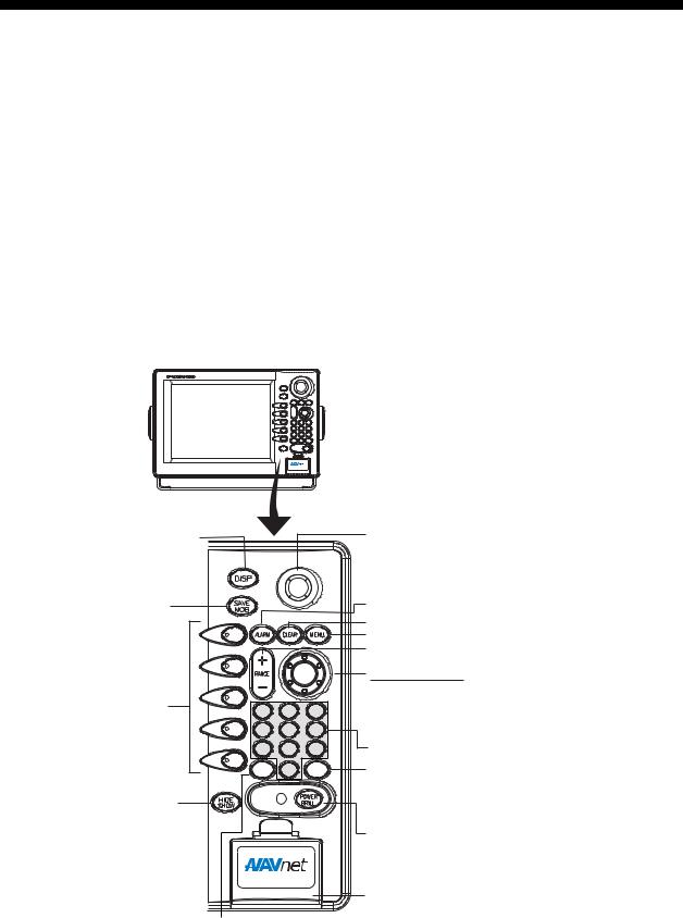
Display unit controls
The radar, video plotter, sounder and chart systems are operated with the controls of the display unit. Ten keys are labeled and they provide the function shown on their labels. The five soft keys provide various functions according to current operating mode. The ENTER knob mainly functions to register selections on the menu and adjust the EBL, VRM and gain. The Trackball’s main function is to move the cursor across the screen. When you correctly execute an operation, the unit generates a beep. Invalid operation causes the unit to emit three beeps.
Displays the mode |
Trackball* |
|
selection window. |
Shifts cursor EBL/VRM and |
|
cursor; selects menu items and options. |
||
|
||
Momentary press: |
Opens/closes the alarm menu. |
|
Registers own ship's |
Clears data; erases selected mark. |
|
position as a waypoint. |
Opens/closes the main menu. |
|
Press three seconds: |
Selects a range. |
Marks man overboard |
|
|
|
ENTER knob |
position. |
|
|
|
Push: Registers setting. |
Soft keys |
ABC |
DEF |
GHI |
Rotate: Adjusts, gain, VRM, EBL, etc.; |
|
1 |
2 |
3 |
selects menu items and options. May also |
|
4 |
5 |
6 |
be used to enter alphanumeric data. |
|
JKL |
MNO |
PQR |
Enter alphanumeric data. |
|
7 |
8 |
9 |
|
|
STU |
VWX |
YZ& |
Radar: Displays the soft keys for adjustment of |
|
VRM |
0 |
GAIN |
|
|
EBL |
_'# |
|
|
|
|
|
|
gain, A/C SEA and A/C RAIN (FTC in case the |
Shows or hides the soft |
|
|
|
the radar source is MODEL 17x4 series). |
|
|
|
Sounder: Adjusts gain. |
|
keys, function keys, |
|
|
|
|
|
|
|
Long press: Turns power off. |
|
nav data alternately. |
|
|
|
|
|
|
|
|
Momentary press: Turns the power on; |
|
|
|
|
opens the display for adjustment of brilliance |
|
|
|
|
and hue; shows RADAR STBY/TX soft key. |
|
|
|
|
Chart drive |
Displays soft keys for EBL/VRM.
*: When it has been some time since the trackball was last operated, the cursor may not track the movement of the trackball. In this case, move the trackball rapidly and then finely.
1-1

1. OPERATIONAL OVERVIEW
Soft keys
The function of the five soft keys changes according to the operation. Their labels for their current functions are shown on the screen to the left of the keys. To hide or show the soft keys, press the HIDE/SHOW key. Each press of the key shows preset soft keys, user function keys or turns off navigation information (at the top of the screen).
SOFT
KEYS
Display unit
Some soft keys show the current setting of a soft key in reverse video as shown below.
3nm |
319. 9°M TRAIL |
34° 22. |
3456'N |
359.9°M |
TRIP NU |
12/LP |
080° 22. |
3456'E |
19.9 kt |
99.9 nm |
|
H-UP |
|
|
|
|
|
TRAIL |
16.0nm |
|
MARK |
ON /OFF |
|
|
ENTRY |
TRAIL |
|
|
MODE |
TIME |
|
|
NTH UP |
GRAD |
|
|
NAV |
SINGLE |
|
|
POS |
TRAIL |
|
|
|
COLOR |
|
|
|
|
WP-002 |
|
D.BOX |
RETURN |
FISH |
ON/OFF |
|
|
|
|
|
|
|
|
BRIDGE |
+359.9 ˚R
11.70nm
Current option shown in reverse video
Radar Display |
Plotter Display |
Radar and plotter displays
1-2

1. OPERATIONAL OVERVIEW
1.2Inserting a Chart Card
Your unit reads SD cards, in the following formats: Navionics GOLD Chart cards or C-MAP NT+/NT MAX chart cards, depending on the type of display unit you have. Insert the appropriate chart card for your area as follows:
1. Open the chart drive.
Chart drive
Display unit
2.Insert chart card label side up prior to turning on the power.
3.Close the lid.
To remove chart card, follow the steps shown below.
1.Press the MENU key to show the menu.
2.Press the SHOW/HIDE soft key.
3.Open the chart drive lid, and then push the card once and then pull it out.
Note 1: Do not remove a card while the chart is being drawn. This may cause the equipment to freeze.
Note 2: Do not insert or remove a card while the power is on. This may cause the equipment to freeze.
Note 3: For multiple display units, do not use the same chart card type in more than one display unit.
Note 4: Remove the card with care; rough handling can damage the card and destroy its contents.
1-3
1. OPERATIONAL OVERVIEW
1.3Turning the Unit On/Off
Press the POWER/BRILL key to turn the unit on. A beep sounds and then the equipment shows the startup NavNet screen (about 20 seconds), the product information screen, startup test results and chart usage disclaimer. During this period the equipment is inoperative. The startup test checks the ROM, RAM, internal battery and backup data for proper operation, displaying the results for each as OK or NG (No Good). If NG appears an appropriate message appears on the screen. For any NG, try to press any key to go to the chart disclaimer screen, then perform the diagnostic test as shown in the paragraph “8.8 Diagnostics.”
For start up with the radar display, the magnetron takes from one minute and thirty seconds to three minutes (depending on radar model) to warm up before the radar can be operated. The time remaining for warming up of the magnetron is counted down at the center of the display.
You may press any key at the chart disclaimer screen to show the last-used display, or wait several seconds to let the equipment do it for you.
To turn the unit off, press and hold down the POWER/BRILL key until the screen goes off (approx. 3 sec.). To protect the LCD attach the hard cover. Note that the network sounder will be turned off approx. three minutes after turning off the power. This is due to the system’s electrical characteristics.
Note: The first time you turn on the power (or any time the power is applied after a memory reset), you are asked if you want to start the simulation mode, which provides simulated operation of the equipment after the installation mode selection. Push the ENTER knob to start the simulation mode, or press the CLEAR key to start normal operation. For further details about the simulation mode, see the paragraph “1.10 Simulation Display.”
1-4

1. OPERATIONAL OVERVIEW
1.4Display Brilliance, Panel Brilliance, Hue
You can adjust display brilliance, panel brilliance and hue as shown below.
1.4.1Display brilliance, panel brilliance
1.Press the POWER/BRILL key momentarily. A set of soft keys for adjustment of brilliance and hue appear.
Active soft key is highlighted.
3nm |
319. 9°M |
BRILL |
34° 22. |
3456'N |
359.9°M |
TRIPBRILL NU |
12/LP |
CONTST |
080° 22. |
3456'E |
19.9 kt |
CONTST99.9 nm |
|
H-UP |
|
|
16.0nm |
|
|
|
|
|
DISPLY |
|
|
DISPLY |
|
|
|
BRILL |
|
|
|
BRILL |
PANEL |
PANEL |
BRILL |
BRILL |
HUE |
HUE |
|
RADAR |
|
|
|
RADAR |
|
STBY |
WP-002 |
FISH |
|
STBY |
|
|
|
|
||
DISPLAY BRILLIANCE |
RETURN |
|
|
DISPLAYBRIDGEBRILLIANCE |
RETURN |
8 |
+ 359.9 ˚R |
|
|
8 |
|
|
|
|
|||
|
11.70nm |
|
|
|
|
Radar Display |
Plotter Display |
Brilliance adjustment soft keys
2.Press the DISPLY BRILL or PANEL BRILL soft key as appropriate. An adjustment window appears at the bottom of the screen. This window shows the name of the item selected for adjustment plus current brilliance level, by bar graph.
DISPLAY BRILLIANCE  8
8
Display brilliance
PANEL BRILLIANCE  8
8
Panel brilliance
Display brilliance and panel brilliance windows
3.Adjust the ENTER knob, clockwise to raise the setting or counterclockwise to decrease it. You may also use the soft key pressed at step 2. Eight levels of display brilliance and panel brilliance are available.
4.Hit the RETURN soft key to finish.
Note 1: If the unit is turned off with minimum brilliance, the screen will be dark at the next power-up. Press the POWER/BRILL key consecutively to adjust the brilliance.
Note 2: This equipment does not have a contrast control.
1-5

1. OPERATIONAL OVERVIEW
1.4.2Hue
You may select the colors for the radar and plotter displays as below.
1.Press the POWER/BRILL key momentarily.
2.Press the HUE soft key to show the hue setting window.
HUE
▲DAY NIGHT TWILIGHT
MANUAL SET
▼
Hue window
3.Operate the Trackball to select hue desired, referring to the table below. MANUAL SET follows the color settings on the CHART DETAILS menu for the plotter and the RADAR DISPLAY SETUP menu for the radar.
|
Night |
Day |
Twilight |
Characters |
Red |
Black |
Green |
Radar ring |
Red |
Green |
Green |
Radar echo |
Orange |
Multi |
Yellow |
Background |
Black |
White |
Blue |
Landmass (plotter) |
Orange* |
Light-orange* |
Orange* |
*= Beige and light-beige on C-MAP display unit.
4.Hit the RETURN soft key to finish.
Note: When using the overlay screen, the own ship track will be hidden if the radar background and own ship track are blue and the “MANUAL SET” hue setting is used. In this case, set HUE to other position and then return to “MANUAL” to show the own ship track in black.
1-6

1. OPERATIONAL OVERVIEW
1.5Selecting a Display
1.5.1Display modes
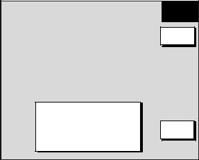
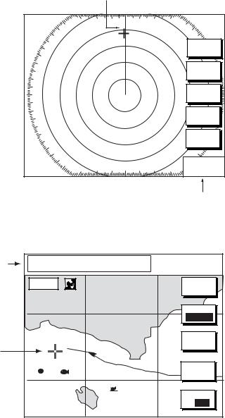
If you have a radar, navigator, network sounder and external video source (video recorder, etc., optional PIP board required) six full-screen displays are available: radar, plotter, echo sounder, nav data, overlay, and external video. In addition to the full-screen display, you can divide the screen into halves and thirds to show two and three sets of images on a combination display.
Full screen |
(radar) |
Combination screen (radar + plotter)
Overlay screen
(plotter + radar only, requires L/L data)
Display screens
The table below shows the displays available with each screen type.
Screen type and available display screen
Full screen |
Combination screen options |
Overlay screen |
|
(halfor thirds-screen) |
options |
|
|
|
Plotter, radar, sounder, |
Plotter, radar, sounder, |
Radar + plotter |
nav data, external |
compass (or wind), highway, |
|
video, overlay |
compass (or wind)/highway, |
|
|
nav data, overlay, external |
|
|
video |
|
|
|
|
1-7
1. OPERATIONAL OVERVIEW
1.5.2Selecting a display
1.Press the DISP key to show the display screen selection window. The icons of modes not available are shaded. HOTPAGE 1-HOTPAGE 6 are user-arrangeable displays called “hot pages,” which you can configure as you like. For further details, see the paragraph “7.6 Hot Page Setup.”
Selected |
|
|
|
|
|
|
|
Basic display |
|
item |
|
|
|
|
|
|
|
||
RADAR |
PLOTTER |
SOUNDER |
NAV DATA |
OVERLAY |
EXT VIDEO |
WX FAX |
screens |
||
|
 Hot pages
HOTPAGE 1 HOTPAGE 2 HOTPAGE 3 HOTPAGE 4 HOTPAGE 5 HOTPAGE 6
·TURN KNOB TO SELECT MODE AND PUSH KNOB TO ENTER.
·PUSH ANY SOFT KEY TO SELECT IMAGE SOURCE.
Display screen selection window
Note: “WX FAX” is available only when the facsimile receiver FAX-30 is connected. If the message “AUX SOURCE IS DISCONNECTED. PUSH ENT KNOB TO EXIT.” appears, press the ENTER knob and select other item.
2.Rotate the ENTER knob to select a basic display screen or a hot page screen.
3.Push the ENTER knob.
4.If you select a basic display screen, a group of appropriate combination displays appear. In the example below, the radar combination screens are shown. When WX FAX is selected at step 2, a combination display does not appear.
PUSH ENTER KNOB. |
RETURN |
Radar combination screen selection window
5.Rotate the ENTER knob to select display desired.
6.Push the ENTER knob to finish.
1-8

1. OPERATIONAL OVERVIEW
1.5.3Switching control in combination and overlay screens
A soft key is provided in relevant combination and overlay screens to switch control between displays. In the example below, the CNTRL PLOTTR and CNTRL SNDR soft keys enable switching control between the plotter and sounder screens in the plotter/sounder combination display.
34° 22. |
3456’N 359.9°M TRIP |
NU |
0’33" |
0 |
|
080° 22. |
3456’E 19.9 kt 99.9 nm |
|
|
|
MARK |
16.0nm |
|
|
40.0 |
|
ENTRY |
|
|
|
|
||
|
|
|
|
50 |
MODE |
|
|
|
|
|
NTH UP |
|
NAV |
100 |
POS |
150 |
CNTRL |
|
PLOTTR |
97 200
WP-002 FISH |
50k |
Plotter display selected
CNTRL |
CNTRL |
PLOTTR |
SNDR |
|
To adjust |
|
To adjust |
|
|
sounder |
|
plotter |
|
34° 22. 3456’N 359.9°M TRIP NU |
0’33" |
0 |
|
|
080° 22. 3456’E 19.9 kt 99.9 nm |
|
|
SHIFT |
|
16.0nm |
|
40.0 |
|
|
|
|
|
||
|
|
|
50 |
MODE |
|
|
|
|
|
|
|
|
100 |
FREQ |
|
|
|
LF/HF |
|
|
|
|
|
|
|
|
|
|
DISPLAY |
|
|
|
150 |
MODE |
|
|
|
CNTRL |
|
|
|
|
|
|
|
|
|
|
SNDR |
|
|
97 |
200 |
|
WP-002 |
FISH |
50k |
|
|
Sounder display selected
How to switch control between modes in the plotter/sounder combination display
1-9
1. OPERATIONAL OVERVIEW
1.5.4Selecting image source
When more than one network radar or network sounder is connected to the equipment, you may select an image source for each as shown below. This is not necessary when only one network radar or network sounder is connected.
1.Press the DISP key.
2.Press any soft key to show the following display.
▲RADAR SOURCE |
1 (HOST NAME: NAVNET1) |
SOUNDER SOURCE |
ETR1 (HOST NAME: SOUNDER) |
AUX SOURCE |
AUX 1 (HOST NAME: WXFAX) |
IP ADDRESS |
172.031.003.003 |
DEVICE NUMBER |
1 (HOST NAME: NAVNET-1) |
IF THERE IS MORE THAN
ONE NETWORK RADAR OR
ECHO SOUNDER, YOU MAY
SELECT THE IMAGE
SOURCES FOR DISPLAY.
SELECT SOURCE
EDIT |
RETURN |
Select source menu
3.Use the Trackball to select RADAR SOURCE, SOUNDER SOURCE or AUX SOURCE as appropriate, then press the EDIT key.
RADAR SOURCE |
|
SOUNDER SOURCE |
|
AUX SOURCE |
▲ 1 (NAVNET1) |
|
▲ ETR0 (SOUNDER) |
|
▲ AUX1 (WXFAX) |
2 (NAVNET2) |
|
ETR1 (SOUNDER1) |
|
AUX2 (WXFAX1) |
3 (NAVNET3) |
|
ETR2 (SOUNDER2) |
|
AUX3 (WXFAX2) |
4 (NAVNET4) |
|
ETR3 (SOUNDER3) |
|
AUX4 (WXFAX3) |
▼ |
|
ETR4 (SOUNDER4) |
|
▼ |
|
|
ETR5 (SOUNDER5) |
|
|
Radar source |
|
|
Aux source |
|
|
ETR7 (SOUNDER7) |
|
||
|
|
ETR6 (SOUNDER6) |
|
|
|
|
ETR8 (SOUNDER8) |
|
|
|
|
ETR9 (SOUNDER9) |
|
|
|
|
▼ |
|
|
|
|
Sounder source |
|
|
Radar source and sounder source windows
4.Use the Trackball to choose source.
5.Push the ENTER knob to set.
6.Press the DISP key to finish.
7.Turn the power off and on again.
1-10
1. OPERATIONAL OVERVIEW
1.6Trackball, Cursor
The Trackball functions to shift the cursor, for measurement of range and bearing to a location (radar) and latitude and longitude position (plotter). Roll the Trackball to shift the cursor. The cursor moves in the direction of Trackball rotation.
Cursor
3nm
12/LP 319. 9°M
H-UP
SIGNAL |
PROC. |
RADAR |
DISPLY |
NAV |
FUNC |
TARGET |
ZOOM &
D. BOX
+ 359.9 ˚R 11.70nm
Cursor Data
Bearing from own ship to cursor
Range from own ship to cursor
Radar Display
Cursor data |
+ |
34° 22. |
3456'N |
272.4°M |
080° 22. |
3456'E |
15.9 nm |
||
L/L position, |
16.0nm |
|
|
|
Range and |
|
|
||
bearing from |
|
|
|
|
own ship to |
|
|
|
|
cursor |
|
|
|
|
Cursor
WP-002 FISH
BRIDGE
TRIP NU
99.9 nm
MARK |
ENTRY |
MODE
NTH UP
CENTER |
GO TO
CURSOR
D. BOX
ON/OFF
Plotter Display
Cursor, cursor data
1-11

1. OPERATIONAL OVERVIEW
1.7Entering the MOB Mark, Setting MOB as Destination
The MOB mark functions to mark man overboard position. You can inscribe the mark from any mode except nav data, when playing back data or conducting any test. Note that this function requires position data.
Note: The function of the SAVE/MOB key depends on the setting of SAVE MOB KEY FUNCTION in the GENERAL SETUP menu. The description below shows the procedure using the default setting. For further details, see Save MOB Key Function on page 7-2.
|
|
MOB |
|
|
|
mark |
|
|
|
|
M |
|
|
|
(MOB) |
Range, bearing |
|
|
|
Man |
Current |
M |
162.5°M |
O |
|||
overboard |
position |
B |
0.49 nm |
|
|
||
MOB Data Box Bearing and range to MOB position
MOB concept
1.Press and hold down the SAVE/MOB key for about three seconds when someone falls overboard. The display shows the waypoint number being saved (youngest empty waypoint number, 001-999) followed by the MOB confirmation window.
Time remaining is counted down while pressing the SAVE/MOB key.
|
|
WAYPOINT SAVED! |
|
|
|
|
|
|
CONTINUE PUSHING |
|
MAN OVER BOARD! |
|||
|
|
|
XXXWPT |
|
|
|
|
|
|
FOR MOB! |
|
|
|
GO TO MOB? |
|
|
|
|
|||||||||||
|
|
|
|
|
|
|
|
|
|
|
|
|
YES ... PUSH ENTER KNOB |
|
|
|
|
|
|
|
|
|
|
|
|
|
|
||
|
|
CONTINUE PUSHING |
|
|
|
|
|
|
XX SEC |
|
NO ... PUSH CLEAR KEY |
|||
|
|
|
FOR MOB! |
|
|
|
|
|
|
|
|
|
|
|
|
|
|
|
|
|
|
|
|
XX = Time remaining is counted down. |
|||||
|
|
|
|
|
|
|
|
|
|
|||||
|
XXX = Waypoint number |
|
|
|
|
|
|
|||||||
|
|
|
|
|
|
|
||||||||
MOB mark messages
2.Push the ENTER knob to select the MOB position as the destination, or press the CLEAR key to only mark current ship’s position as a waypoint. If you select the MOB position as destination;
A full-screen radar, plotter or overlay appears depending on the display in use. (If the MOB key function is “MOB Without Confirmation” the range is automatically set to 0.5 nm.) Further, the waypoint marker appears on the radar display.
The MOB mark “MOB” appears at the MOB position and a blue line runs between it and current position. This line shows the shortest course to the MOB position.
Range and bearing to the MOB position are shown in the MOB data box.
To erase an MOB mark from the plotter display, you must first erase its corresponding waypoint. Place the cursor on the MOB mark, then press the CLEAR key followed by pushing the ENTER knob to erase the waypoint. Then, repeat to erase the MOB mark.
Note: On the plotter display, this function can be done by pressing the uppermost soft key. For detail, see page 7-10.
1-12

1. OPERATIONAL OVERVIEW
1.8Data Boxes
Data boxes, providing navigation data, may be shown on any full-screen display. Up to six data boxes (two in case of large characters) may be shown, and the default data boxes are position (in latitude and longitude), course over ground, speed over ground and trip log. The user may choose which data to display, where to locate it, and show or hide it as desired. In addition, data boxes may be set independently for each display mode (plotter, radar, sounder). For how to select data for the data boxes, see the paragraph “7.5 Data Boxes Setup.”
3nm |
319. 9°M |
° |
|
|
|
|
12/LP |
3456'N |
359.9°M |
TRIP |
NU |
||
H-UP |
|
34° 22. |
||||
|
080 22. |
3456'E |
19.9 kt |
99.9 nm |
|
SIGNAL |
16.0nm |
MARK |
PROC. |
|
ENTRY |
RADAR |
|
MODE |
DISPLY |
|
NTH UP |
NAV |
NAV |
FUNC |
POS |
TARGET
TRIP LOG
Data |
177nm |
|
|
ZOOM & |
|
WP-002 FISH |
|
|
|
|
|
|
|
|
|
|
|
boxes |
POSITION |
COG |
SOG |
D. BOX |
Data |
TRIP LOG |
|
D.BOX |
122°36.496'W |
323.6°M |
20.0 kt |
|
177nm |
|
ON/OFF |
||
|
47°58.535'N |
|
|
+ 359.9 ˚R boxes |
|
|
|
|
|
|
|
|
47°58.535'N |
COG |
SOG |
||
|
|
|
|
11.70nm |
|
POSITION |
|
|
|
|
|
|
|
122°36.496'W |
323.6°M |
20.0 kt |
|
|
|
Radar Display |
|
|
|
|
Plotter Display |
|
Data boxes
1.8.1Showing, hiding data boxes with soft key
Plotter: D. BOX ON/OFF
Radar: ZOOM & D. BOX → D. BOX ON/OFF (EBL/VRM data box, cursor data box also shown/hidden)
Sounder: AUTO/D. BOX→D. BOX ON/OFF
1.8.2Rearranging data boxes
You may select the location for data boxes as follows:
1.Using the Trackball, place the cursor inside the data box you wish to move. As the cursor enters the box it changes to a “hand”. Push the ENTER knob, and the hand changes to a fist, meaning the box is correctly selected.
2.Use the Trackball to move the data box to the location desired, then push the ENTER knob.
1.8.3Temporarily erasing a data box
If a data box is obscuring a desired object, you may temporarily erase the box. Use the Trackball to place the cursor inside the data box you wish to erase, then press the CLEAR key. To redisplay the box, press the D. BOX soft key twice to display it.
1-13

1. OPERATIONAL OVERVIEW
1.9Function Keys
The function keys provide for one-touch execution of a desired function. The default function key settings are as shown in the table below.
Function |
|
Default Setting, Key Label |
||
Key |
|
|
|
|
Radar |
|
Plotter |
Sounder |
|
|
|
|||
|
|
|
|
|
#1 |
Heading line on/off, HL |
|
Track on/off, TRK |
TLL output, TLL |
|
|
|
|
|
#2 |
Rings on/off, RNG |
|
Edit mark/line, EML |
Clutter, CLT |
|
|
|
|
|
#3 |
Echo trail, TRL |
|
Ruler, RUL |
Signal level, SLV |
|
|
|
|
|
#4 |
Offcenter, OFC |
|
Add new waypoint, |
Noise limiter, NL |
|
|
|
ADD |
|
|
|
|
|
|
#5 |
STBY/TX, TX |
|
Waypoint |
Picture advance, PA |
|
|
|
alphanumeric list, ALP |
|
|
|
|
|
|
Executing a function
1.Press the HIDE/SHOW key to replace the preset soft key labels with the function key labels.
3nm |
|
34° 22. 3456'N |
359.9°M |
TRIP |
NU |
|
|
12/LP |
319. 9°M |
|
|||||
080° |
22. 3456'E |
19.9 kt |
99.9nm |
|
|
||
H-UP |
|
|
|
|
|
|
|
|
H |
16.0 nm |
|
|
|
T |
|
|
L |
|
|
|
|
|
|
|
R |
|
|
|
|
R |
|
|
|
|
|
|
K |
|
|
|
N |
|
|
|
|
|
|
|
|
|
|
|
E |
|
|
|
G |
|
|
|
|
|
|
|
T |
|
|
|
|
M |
|
|
Function |
|
|
|
L |
|
|
|
L |
|
|
|
|
||
|
|
|
|
R |
|
||
|
R |
|
|
|
|
|
Function |
|
O |
keys |
|
|
|
U |
|
|
F |
|
|
|
|
L |
keys |
|
C |
002WP |
|
|
|
A |
|
|
|
FISH |
|
|
D |
|
|
|
T |
|
|
BRIDGE |
|
D |
|
|
X |
|
|
|
A |
|
|
|
|
|
|
|
|
L |
|
|
|
|
|
|
|
P |
|
+359.9 ˚R
11.70nm
Radar Display |
Plotter Display |
|
Function keys
2. Press function key desired.
Note: Function keys can be individually programmed for the plotter, radar and sounder displays. For further details see the following:
Radar: paragraph 7.2.3
Plotter: paragraph 7.3.2
Sounder: paragraph 7.9.4
1-14

1. OPERATIONAL OVERVIEW
1.10 Simulation Display
The simulation display, for use by service technicians for demonstration purposes, provides simulated operation to help acquaint you with the many features your unit has to offer. It allows you to view and control a simulated plotter, radar and sounder picture, without position-fixing equipment, network radar or a network sounder. Most controls are operative, thus you may practice setting destination, enter waypoints, measure range and bearing to a target, etc. Three simulation displays are provided for both the radar and echo sounder.
The simulation icon (SIM) appears when any simulation mode is active.
To start the simulation display;
1.Press the MENU key.
2.Press the SYSTEM CONFIGURATION, SYSTEM SETUP and SIMULATION SETUP soft keys in that order.
RADAR |
LIVE |
PLOTTER |
LIVE |
SOUNDER |
LIVE |
SPEED |
00.0kt |
COURSE |
000.0° |
LATITUDE |
45°35.000'N |
LONGITUDE |
125°00.000'W |
START DATE & TIME |
00:00 01.APR.00 |
GET RADAR SIMULATION DATA NO
SIM
SETUP
EDIT |
RETURN |
Simulation setup menu
3.Follow appropriate procedure on the next several pages. To stop the simulation mode and return to normal operation, choose LIVE for radar, sounder or plotter.
Radar
NavNet display unit-generated echoes or user data
1. Select RADAR, then press the EDIT soft key.
RADAR
▲BUILT IN DATA 1 BUILT IN DATA 2 USER DATA LIVE
▼
2.Select BUILT IN DATA 1 or 2 for internally generated echoes or USER DATA for user-saved radar data. Push the ENTER knob.
3.Press the MENU key to close the menu.
1-15

1. OPERATIONAL OVERVIEW
NavNet radar antenna-generated echoes (not available with the GD-1920C)
1.Select GET RADAR SIMULATION DATA, then press the EDIT soft key.
2.Select YES, then push the ENTER knob to erase simulation data and get new data. The message “Now getting demo data. Do not turn off display unit.” appears while the unit is receiving radar data.
|
Note: If the network radar could not be found “Radar source is not found. Cannot get |
|||
|
demo data.” appears. And if the radar is not active, the message “Radar is not active. |
|||
|
Cannot get demo data.” is displayed. Check that the radar is plugged in and its signal |
|||
|
cable is firmly fastened. |
|
|
|
3. |
Select RADAR, then press the EDIT soft key. |
|
|
|
4. |
Select SIMULATION 2, then push the ENTER knob. |
|
|
|
5. |
Press the MENU key to close the menu. |
|
|
|
Plotter |
|
|
||
1. |
Select PLOTTER, then press the EDIT soft key. |
|
|
|
PLOTTER |
|
|||
2. |
Select SIMULATION, then push the ENTER knob. |
|||
3. |
Select SPEED, then press the EDIT soft key. |
▲ |
||
4. |
Enter speed (setting range, 0-99 kt, default speed, 0 kt) with |
SIMULATION |
||
LIVE |
||||
|
the alphanumeric keys, then push the ENTER knob. |
▼ |
||
5.Select COURSE, then press the EDIT soft key.
6.Select “8 FIGURE” to trace the simulated ship’s track in a figure-eight course, or enter your own course at DIRECTION. To enter course, use the Trackball to select digit, and enter value with the alphanumeric keys.
7.Press the ENTER soft key.
8.Select LATITUDE, then press the EDIT soft key.
9.Enter latitude (setting range, 85°N-85°S, default setting, 45°35.000’N), then push the
ENTER knob.
10.Select LONGITUDE, then press the EDIT soft key.
11.Enter longitude (setting range, 180°E-180°W, default setting, 125°00.000’W), then push the ENTER knob.
12.Select START DATE & TIME, then press the EDIT soft key.
13.Enter start date and time, then push the ENTER knob.
14.Press the MENU key to close the menu.
Sounder
1.Select SOUNDER, then press the EDIT soft key.
2.Select BUILT IN DATA (internally generated echoes) or ETR (network sounder-generated echoes), then push the
ENTER knob.
Note: The depth, shift, bottom-zoom, bottom-lock and bottom discrimination cannot be shown in the BUILT IN DATA mode.
3. Press the MENU key to close the menu.
SOUNDER
▲BUILT IN DATA ETR DATA LIVE
▼
1-16

2. RADAR OPERATION
This chapter covers radar operation, including the ARP (Auto Plotter) function. ARP requires a Model 18x4C/19x4C series network radar equipped with the ARP circuit board.
2.1Radar Display
North marker |
|
|
Guard zone 2 |
|
|
|
|
||
|
|
|
|
|
|
|
|||
(Head-up, Course-up mode) |
Cursor |
|
|
|
|
||||
|
|
|
|
|
|
|
Heading |
|
|
Range/ |
Pulselength |
|
|
|
|
|
|
||
|
|
Heading line |
|
|
M: Magnetic |
|
|||
range ring |
|
|
|
|
|
|
|
||
|
|
|
|
|
|
T: True |
|
||
interval |
|
|
|
|
|
|
|
|
|
|
|
|
|
|
|
|
|
|
|
Presentation |
|
3nm |
|
|
|
° |
|
TRAIL 30m |
Trail time |
12/LP |
|
|
319. 9 |
M |
|||||
mode |
H-UP |
|
|
|
02m30s |
Trail elapsed time |
|||
Alarm icon |
|
|
|
|
|
|
|
G1 IN |
Guard zone 1 |
EBL1 |
|
|
|
|
|
|
|
G2 OUT |
Guard zone 2 |
Battery icon |
|
|
|
|
|
|
|
ES H |
Echo stretch |
SI |
|
|
|
|
|
|
EAV L |
Echo averaging |
|
Simulation |
|
|
|
|
|
|
|||
mode |
|
M |
|
|
|
|
|
IR L |
Interference rejector |
|
|
|
|
|
|
|
|
|
|
Guard zone 1 |
|
|
|
|
|
|
|
VRM2 |
|
Range ring |
|
|
|
|
|
|
|
|
|
|
|
|
|
|
|
|
|
EBL2 |
|
|
|
|
|
|
|
|
|
|
|
VRM1 |
|
|
|
|
|
|
|
|
Own ship vector |
|
|
|
|
|
|
|
|
(ARP-equipped model, |
|
|
|
|
|
|
|
|
|
|
|
|
|
|
|
|
|
|
|
|
true vector mode) |
Zoom area |
|
|
|
|
|
|
|
|
Zoom |
|
|
|
|
|
|
|
|
|
|
|
|
|
|
|
|
|
|
|
window |
EBL1 bearing |
EBL1 27.0°R |
EBL2 |
327.1°R |
|
|
+ 359.9 °R |
Cursor range |
||
VRM1 range |
VRM15.666nm |
VRM2 |
8.212nm |
|
|
11.70nm |
|||
|
|
|
|
|
|
|
|
|
and bearing |
|
|
|
EBL2 bearing, VRM2 range |
(Cursor position may |
|||||
|
|
|
also be shown, in |
||||||
|
|
|
|
|
|
|
|
|
|
|
|
|
|
|
|
|
|
|
L/L or Loran C TD.) |
Radar display
2.2Transmitting, Stand-by
1.Confirm that the network radar is plugged in.
2.Press the DISP key to select a radar display.
3.Press the POWER/BRILL key momentarily.
4.Press the RADAR STBY soft key to highlight TX on its label.
5.Press the RETURN soft key.
When the radar picture is not required, but you want keep it in a state of readiness, press the RADAR TX soft key to highlight STBY on its label.
2-1
Loading...