


FinePix S602
DIGITAL CAMERA
FinePix S602 ZOOM
SERVICE MANUAL
U/E/EG-Model
FUJI PHOTO FILM CO., LTD.
Ref.No.:ZM00441-100
Printed in Japan 2002.5(NT)
WARNING
THE COMPONENTS INDENTIFIED BY MARK IN THE PARTS LIST SHOULD BE REPLACED
ONLT BY THE COMPONENTS SPECIFIED IN THE PARTS LIST.
RISK OF FIRE AND ELECTRIC SHOCK.
2
FinePix S602 ZOOM SERVICE MANUAL
1. Check the area of your repair for unsoldered or
poorly soldered connections. Check the entire
board surface for solder splasher and bridges.
2. Check the interboard wiring to ensure that no
wires are “pinched” or contact high-wattage
resistors.
3. Look for unauthorized replacement parts, particu-
larly transistors, that were installed during a
previous repair. Point them out to the customer
and recommend their replacement.
4. Look for parts which, though functioning, show
obvious signs of deterioration. Point them out to
the customer and recommend their replacement.
5. Caution:
For continued protection against
fire hazard, replace only with same
type 2.5 amperes 125/250 volts
fuse.
Attention:
Afin d’assurer une protection
permanente contre les risques
d’incendie, remplacer uniquement
par un fusible de meme, type 2.5
amperes, 125/250 volts.
6. Warning:
To reduce the electric shock, be
careful to touch the parts.
SAFETY CHECK-OUT
After correcting the original problem, perform the following
safety check before returning the product to the customer.
WARNING!
HIGH VOLTAGE
RISK OF FIRE-
REPLACE FUSE
AS MARKED
2.5A 125/250V
2.5A 125/250V

3
FinePix S602 ZOOM SERVICE MANUAL
TABLE OF CONTENTS
TABLE OF CONTENTS
1.Specifications
1-1.Product Specifications ....................................................... 4
1-2.Camera Features................................................................6
1-3.Names of External Components ......................................7
2.Disassembly
2-1.Names of Internal Components .......................................9
2-2.How to remove R CABI CONST .................................... 10
2-3.Decomposition of R CABI CONST................................ 1 1
2-4.How to remove LCD ASSY ............................................ 1 2
2-5.How to remove TOP CABI CONST ............................... 13
2-6.Decomposition of TOP CABI CONST .......................... 1 7
2-7.How to remove LCD FRAME CONST ........................... 19
2-8.Decomposition of LCD FRAME CONST ...................... 20
2-9.Decomposition of MAIN PWB ASY............................... 2 0
2-10.How to remove SHEET FRAME .................................. 21
2-11.How to remove BATTERY LID .................................... 21
2-12.How to remove BATTERY HOLDER UNIT ................ 22
2-13.How to remove CAM PWB ASSY ............................... 22
2-14.How to remove LENS FRAME ..................................... 23
2-15.How to remove LENS CONST ..................................... 23
2-16.How to remove LENS CABI ASSY ............................. 24
2-17.How to remove SIDE MODULE UNIT ........................ 25
2-18.How to remove AF SENSOR UNIT ............................. 26
3.Schematic
3-1.Cautions ............................................................................ 27
3-2.Overview of Functions of Each Circuit ......................... 27
3-3.Functions of Primary Blocks .......................................... 28
3-3-1.Technical Outline ..................................................... 28
3-3-2.CAM Board Block Functions .................................. 28
3-3-3.MAIN Board Block Functions ................................. 28
3-3-4.DCTS Board Block Functions ................................ 2 8
3-4.Block Diagram ................................................................. 29
3-5.Overall ............................................................................... 30
3-6.Board mounting diagram ................................................ 31
3-6-1.CAM PWB ASSY Component Location (A) .......... 31
3-6-2.CAM PWB ASSY Component Location (B) .......... 32
3-6-3.KEY PWB ASSY Component Location (A) .......... 33
3-6-4.KEY PWB ASSY Component Location (B) .......... 34
3-6-5.MAIN PWB ASSY Component Location (A) ........ 3 5
3-6-6.MAIN PWB ASSY Component Location (B) ........ 3 6
3-6-7.DCST PWB ASSY Component Location (A) ........ 37
3-6-8.DCST PWB ASSY Component Location (B) ........ 38
4.Adjustment
4-1.Adjustments to Primary Components Following
Replacement ................................................................... 39
4-2.Preparation for adjustments .......................................... 40
4-2-1.Measuring Equipments............................................ 40
4-2-2.Jigs and Charts ........................................................ 40
4-2-3.Connection ................................................................ 41
4-2-4.Environmental Settings for Adjustment ................ 42
4-2-5.Preparations for AF Sensor Adjustment ............... 42
4-2-6.Environmental Settings for
AF Sensor Adjustment ........................................... 42
4-2-7.Environmental settings for AF adjustment ........... 43
4-2-8.Environmental settings for Flash adjustment ...... 43
4-3.About the Adjustment PC Soft ...................................... 44
4-3-1.Attention at DSC jig driver ...................................... 44
4-3-2.Attention at PC adjustment soft ............................. 4 5
4-3-3.Attention at Firmware .............................................. 46
4-3-4.Content of Adjustment Software ............................ 47
4-3-5.Starting the Adjustment Software .......................... 4 7
4-3-6.Customizing of Adjustment Software .................... 48
4-3-7.Use of each command ............................................ 50
4-4.Adjustment of Components (for PC adjustment) ........ 51
4-4-1.Starting the Adjustment Software
(cautions during use).............................................. 51
4-4-2.Camera Jig Mode Procedure.................................. 51
4-4-3.AF Sensor Adjustment ............................................ 52
4-4-4.CCD Data Input ........................................................ 5 4
4-4-5.Preparing the CCD Defect Data (FD) ................... 55
4-4-6.CAM Adjustment ...................................................... 56
4-4-7.Zoom/AF Adjustment ............................................... 57
4-4-8.Flash Adjustment ..................................................... 58
4-4-9.Battery Adjustment .................................................. 59
4-4-10.Mode Dial Voltage Adjustment ............................ 60
4-4-11.End Setting ............................................................. 61
5.Inspection
5-1.Preparation for inspection .............................................. 62
5-1-1.Measuring Equipments............................................ 62
5-1-2.Jigs and Charts ........................................................ 62
5-1-3.Connection ................................................................ 63
5-2.Inspection ......................................................................... 64
5-2-1.External Inspection .................................................. 6 4
5-2-2.Power Supply Switch Check................................... 64
5-2-3.Checking Shock Noise in the Movie Mode ........... 64
5-2-4.EVF Check ................................................................ 64
5-2-5.Resolution Check ..................................................... 65
5-2-6.Y Level Check .......................................................... 6 6
5-2-7.Flash Photography Check ...................................... 6 7
5-2-8.Manual Focus Check ............................................... 68
5-2-9.Macro Operation Check .......................................... 68
5-2-10.External Flash Operation Check.......................... 68
5-2-11.Command Dial Check ........................................... 6 8
5-2-12.Movie/Audio Check ................................................ 68
5-2-13.Erase Mode Check ................................................ 68
5-2-14.Low Battery Check................................................. 69
5-2-15.Current Consumption Check ................................ 69
5-2-16.LCD Display Image Check ................................... 69
5-2-17.EVF Display Image Check.................................... 70
5-2-18.Power OFF Operation Check ............................... 70
5-2-19.Settings at Shipment ............................................. 71
5-2-20.Clock Setup and Clear .......................................... 71
6.Parts List
6-1.U-Model ............................................................................ 72
6-2.E-Model ............................................................................. 77
6-3.EG-Model .......................................................................... 82
6-4.Electrical Parts (U/E/EG-Model commonness) ........... 87
7.Appendix
7-1.List of Related Technical Updates Issued ................... 88

4
FinePix S602 ZOOM SERVICE MANUAL
1. Specifications
System
Model Digital camera FinePix S602 ZOOM
Number of effective pixels 3.1million pixels
CCD sensor 1/1.7 inch Super CCD in an interwoven pattern
Number of total pixels 3.3 million pixels
Number of recorded pixels 2832 x 2128 pixels (6.03 million pixels) /2048 x 1536 pixels/1280 x 960 pixels/640 x 480 pixels
Storage media SmartMedia (3.3V), Microdrive
File format Still image: TIFF-RGB, JPEG (Exif ver. 2.2)
* Design rule for Camera File System compliant DPOF compatible
Movie: AVI format, Motion JPEG
Audio: WAV format
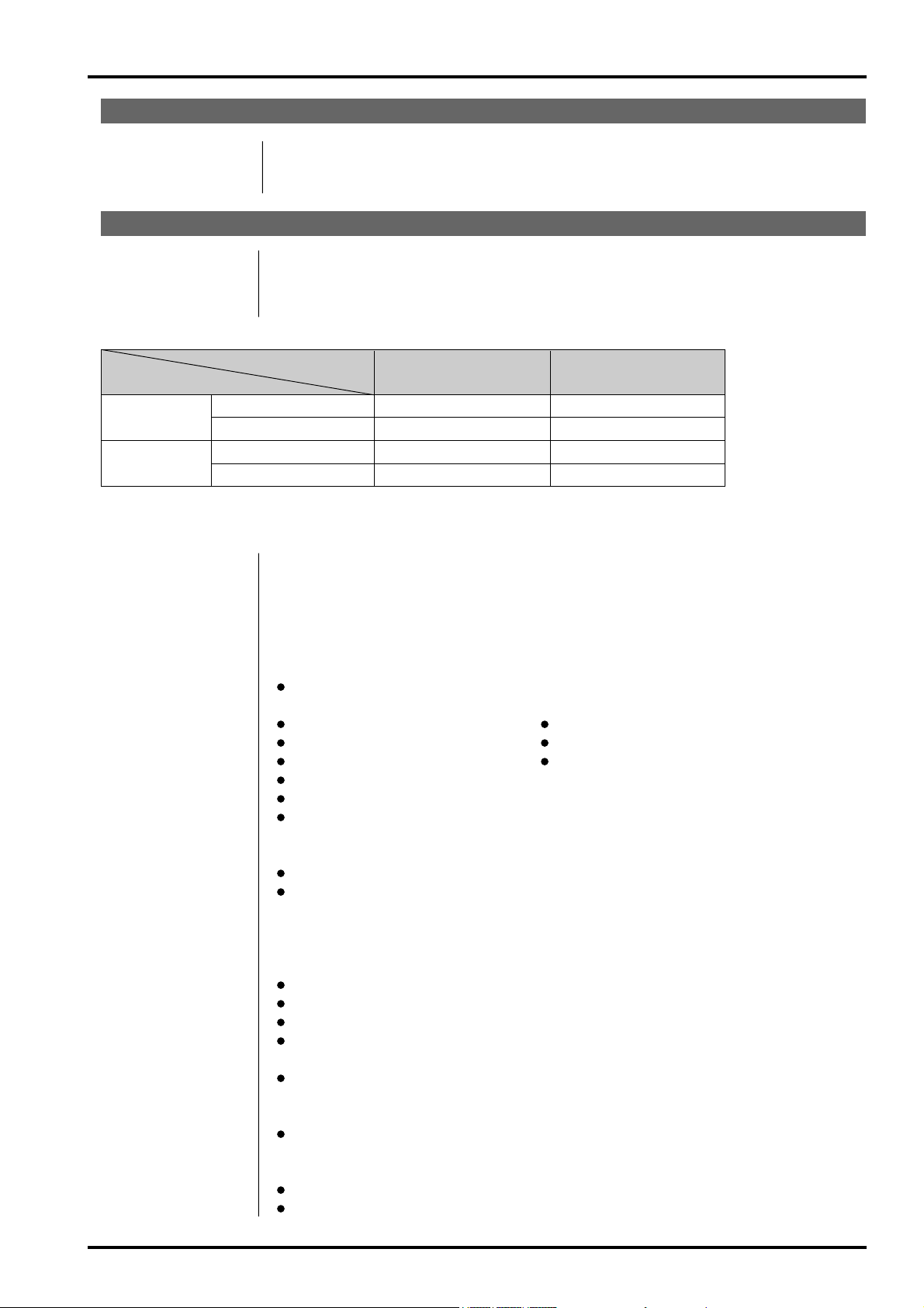
Standard number of shots per Media
Number of recorded
2832x2128 2048x1536 1280x960
640
x
480
Movie (Video)
Pixels
Quality Mode HI FINE
NORMAL
BASIC FINE
NORMAL
FINE
NORMAL NORMAL
Approx. Approx. Approx. Approx. Approx. Approx. Approx. Approx. Approx.
Image File Size
18MB 2.4MB 1.2MB 460KB 1.3MB 590KB 620KB 320KB 130KB
__
MG-4S (4MB) 0 1 3 8 2 6 6 12 30 Approx. 3 sec. Approx. 6 sec.
MG-8S (8MB) 0 3 6 17 6 13 12 25 61 Approx. 6 sec. Approx. 13 sec.
MG-16S (16MB) 0 6 13 33 12 26 25 49 122 Approx. 13 sec. Approx. 27 sec.
MG-32S (32MB) 1 13 28 68 25 53 50 99 247 Approx. 27 sec. Approx. 55 sec.
MG-64S (64MB) 3 26 56 137 50 107 101 198 497 Approx. 55 sec. Approx. 110 sec.
MG-128S (128MB) 7 53 113 275 102 215 204 398 997 Approx. 112 sec. Approx. 222 sec.
Microdrive (340MB) 19 147 311 7 65 27 9 58 9 566 1119 2729 Approx. 307 sec. Approx. 609 sec.
Microdrive (1GB) 59 443 938 2190 842 1729 1642 3285 8213 Approx. 925 sec. Approx.
1833
sec.
1. Specifications
1-1. Product Specifications
Sensitivity Equivalent to ISO 160/200/400/800/1600
Lens Super EBC Fujinon 6x optical zoom lens
Focus distance f = 7.8 mm-46.8 mm (Equivalent to 35 mm-210 mm on a 35 mm camera)
Viewfinder 0.44-inch 180,000 pixles electronic viewfinder
Exposure control TTL 64-zones metering, Program AE ( , , , , ), Exposure compensation ( , , )
available
White balance , : Fully automatic
, , : 8 positions selectable.
Custom white balance selectable (2 positions)
Focal range Normal (wide-angle): Approx. 50 cm (1.6 ft.) to infinity
Normal (telephoto-angle): Approx. 90 (3.0 ft.) cm to infinity
Macro: Approx. 10 cm (3.9 in.) to 80 cm (2.6 ft.)
Super Macro: Approx. 1 cm (0.4 in.) to 20 cm (7.9 in.)
Shutter : Variable-speed, 1/4 sec. to 1/2000 sec.
: Variable-speed, 3 sec. (Night scenes only) to 1/2000 sec.
, , : Variable-speed, 3 sec. to 1/1000 sec.
: Variable-speed, 15 sec. to 1/10000 sec.
Aperture F2.8-F11 13 levels in 1/3 EV steps
Focus Passive-type external AF sensor + CCD-AF sensor
Focus mode: AF, AREA AF, MF
Self-Timer 2 sec./10 sec. timer clock
LCD monitor 1.8 inches, low-temperature polysilicon TFT 110,000 pixels
Flash Auto flash using flash control sensor
Effective range: Wide-angle: Approx. 0.3 m-5.4 m (1.0 ft.-17.7 ft.)
Telephoto-angle: Approx. 0.9 m-5.0 m (3.0 ft.-16.4 ft.)
Flash modes: Auto, Red-Eye Reduction, Forced Flash, Slow Synchro, Red-Eye Reduction
+ Slow Synchro
5
FinePix S602 ZOOM SERVICE MANUAL
1. Specifications
Input/Output Terminals
DC Input To connect the AC power Adapter AC-5V/AC-5VH/AC-5VHS
Accessory shoe Hot shoe
A/V Output Stereo mini-jack (1)
Power Supply and Others
Power supply Use one of the following
* 4 x AA-size alkaline batteries
* 4 x AA-size Ni-MH (nickel-metal hydride) batteries (sold separately)
* AC Power Adapter AC-5VH/AC-5VHS (sold separately)
Available shots using batteries (When fully charged)
Battery type
Alkaline batteries
Ni-MH batteries
Media type HR-3UF 1700 mAh
SmartMedia
Using LCD monitor Approx. 200 frames Approx. 250 frames
Using EVF Approx. 210 frames Approx. 280 frames
Microdrive
Using LCD monitor Approx. 170 frames Approx. 230 frames
Using EVF Approx. 180 frames Approx. 240 frames
The number of shots shown here is an approximate guide to the number of consecutive shots that can be
taken based on 50% flash usage at normal temperatures. However, the actual number of available shots
will vary depending on the ambient temperature when the camera is used and the amount of charge in the
battery. The number of available shots will be lower in cold conditions.
Conditions for use Temperature: 0
o
C to +40
o
C (+32
o
F to +104
o
F)
80% humidity or less (no condensation)
Camera dimensions 121.0 mm x 81.5 mm x 97.0 mm/4.8 in. x 3.2 in. x 3.8 in.
(W/H/D) (not including accessories and attachments)
Camera mass (weight) 500 g/17.6 oz. (not including accessories, batteries or media)
Weight for photography Approx. 600 g/21.2 oz. (including batteries and SmartMedia)
Accessories
SmartMedia (16MB, 3.3V) (1) Supplied with: Anti-static case (1)
Index label (1)
AA-size alkaline batteries (4) Shaulder Strap (1)
Protective cover (2) Metal strap clip (2)
Clip attaching tool (1) Lens cap (1)
Lens cap holder (1)
A/V Cable (approx. 1.5 m (4.9 ft.), mini-plug (2.5 mm dia.) to pin-plug cable x 2) (1)
USB Interface Set (1) * CD-ROM: Software for FinePix EX (1)
* Special USB cable with Noise Suppression core (1)
* Software Quick Start Guide (1)
Owner's Manual (1)
Optional Accessories
SmartMedia
MG-4S: 4MB, 3.3V MG-8S: 8MB, 3.3V MG-16S: 16MB, 3.3V
MG-32S: 32MB, 3.3V MG-64S: 64MB, 3.3V
MG-16SW: 16MB, 3.3V, ID MG-32SW: 32MB, 3.3V, ID
MG-64SW: 64MB, 3.3V, ID MG-128SW : 128MB, 3.3V, ID
AC-5VH/AC-5VHS AC Power Adapter
Fujifilm Rechargeable Battery 2HR-3UF
Fujifilm Battery Charger with Battery BK-NH (Not Available in U.S.A./Canada)
FD-A2 Floppy Disk Adapter (FlashPath)
Windows 95/98/98 SE/Me/NT 4.0, Mac OS 7.6.1 to 9.1
SM-R2 Image Memory Card Reader
Compatible with Windows 98/98 SE, Windows Me, Windows 2000 Professional or
iMac or Power Macintosh and models that support USB as standard.
DM-R1 Image Memory Card Reader
Compatible with Windows 98 SE, Windows 2000 Professional (read-only), iMac DV
and Power Macintosh PCs with FireWire as a standard feature. Mac OS 8.5.1 to 9.1
PC-AD3 PC Card Adapter
SC-FX602 Soft Case

6
FinePix S602 ZOOM SERVICE MANUAL
1. Specifications
1-2. Camera Features
3.1 million effective pixels
1/1.7-inch Super CCD provides high quality images with 2832 ×2128 (6.03 million) recorded pixels
Powerful Super EBC Fujinon 6optical zoom lens (aspherical lens) for superb optical performances
Maximum 4.4seamless digital zoom
Wide range of light sensitivity settings from ISO 160, 200, 400 up to ultra-high settings with ISO 800* and 1600*
* In 1280 ×960 pixels mode only
“Motion Photo” VGA-sized movie with monaural sound (640 ×480 pixels at 30 frames/sec.)
Dual media slots for SmartMedia and Microdrive
Fast-acting dual-method focusing system that combines an external AF sensor (passive phase-difference AF sensor)
and CCD-AF
Quick, responsive operation with 3 second start-up and only 1 Second between shots
Auto focus with macro function (manual focusing function also available)
Super Macro function for close-up shots as near as 1cm (0.4 inch) to the subject
Three type high-speed continuous shooting mode
Top 5-frame continuous shooting (5 frames/sec.)
Final 5-frame continuous shooting (5 frames/sec. within 5 seconds/25 shots)
Long-period continuous shooting with 1280 ×960 pixels mode (1.8 frames/sec. up to 40 frames)
AF AREA function lets you choose from 49 focusing points in the view finder image
A wide range of exposure modes (including manual exposure) let you adjust your photography settings as you like
A ultra-wide range of shutter speed from 1/10,000 sec to long exposures up to 15 sec in Manual mode
0.44” 180,000-pixel electric viewfinder with diopter adjustment mechanism
1.8” 110,000-pixel LCD monitor (low-temperature polysilicon TFT) with 100% coverage
Support to external flash units
Convenient preview function for checking your shots
Immediate exposure checking after shooting using histogram indication function
Playback zoom function (max. 18)
Multiple exposure and monochrome photography function provides a wider range of photography options
INFO button allows you to view your photography settings at a touch whenever the need arises
Easy high-speed data transfer via the USB connection
Conforms to “Design for Camera File system” standard and Exif ver 2.2 for digital cameras
* “Design for Camera File system” standard and Exif format are formulated by the Japanese Electronic and Informa-
tion Association (JEITA)
Explanation of Terms
AF/AE Lock: On the FinePix S602 ZOOM, pressing the shutter button down half way locks the focus and exposure settings
(AF and AE lock). If you want to focus on a subject that is not centered in the frame or change the picture
composition after the exposure is set, you can obtain good results by changing the composition after the AF
and AE settings are locked.
Auto Power Save Function: If the camera is not used in any way for 30 seconds, this function switches features such as the LCD monitor
off (Sleep mode) to prevent battery depletion and the waste of power when the AC power adapter is
connected. If the camera is then left unused for a further period, the Auto Power Save function switches the
camera off. This period can be set to 2 minutes or 5 minutes on this camera. h The Auto Power Off function
does not operate in PC mode, during automatic playback, or if it is disabled during setup.
DPOF: Digital Print Order Format DPOF is a format used for recording information on a storage media (image
memory card, etc.) that allows you to specify which of the frames shot using a digital camera are printed and
how many prints are made of each image.
EV: A number that denotes Exposure Value. The EV is determined by the brightness of the subject and sensitivity
(speed) of the film or CCD. The number is larger for bright subjects and smaller for dark subjects. As the
brightness of the subject changes, a digital camera maintains the amount of light hitting the CCD at a constant
level by adjusting the aperture and shutter speed. When the amount of light striking the CCD doubles, the EV
increases by 1. Likewise, when the light is halved, the EV decreases by 1.
JPEG: Joint Photographics Experts Group A file format used for compressing and saving color images. The
compression ratio can be selected, but the higher the compression ratio, the poorer the quality of the
expanded image.
Motion JPEG: A type of AVI (Audio Video Interleave) file format that handles images and sound as a single file. Images in
the file are recorded in JPEG format. Motion JPEG can be played back by QuickTime 3.0 or later.
PC Card: A generic term for cards that meet the PC Card Standard.
PC Card Standard: A standard for PC cards determined by the PCMCIA.
PCMCIA: Personal Computer Memory Card International Association (US).
VGA/QVGA: Graphics standards for PCs. Images are displayed at 640 ×480 and 320 ×240 pixels respectively.
WAVE: A standard format used on Windows systems for saving audio data. WAVE files have the “.WAV” file
extension and the data can be saved in either compressed or uncompressed format. This camera use PCM
recording. WAVE files can be played back on a personal computer using the following software :
Windows:MediaPlayer Macintosh:QuickTime Player QuickTime 3.0 or later
White Balance: Whatever the kind of the light, the human eye adapts to it so that a white object still looks white. On the other
hand, devices such as digital cameras see a white subject as white by first adjusting the color balance to suit
the color of the ambient light around the subject. This adjustment is called matching the white balance. A
function that automatically matches the white balance is called an Automatic White Balance function.
Smear: A phenomenon specific to CCDs whereby white streaks appear on the image when there is a very strong light
source, such as the sun or reflected sunlight, in the photography screen.
Exif Print: Exif Print Format is a newly revised digital camera file format that contains a variety of shooting information for
optimal printing.

7
FinePix S602 ZOOM SERVICE MANUAL
1. Specifications
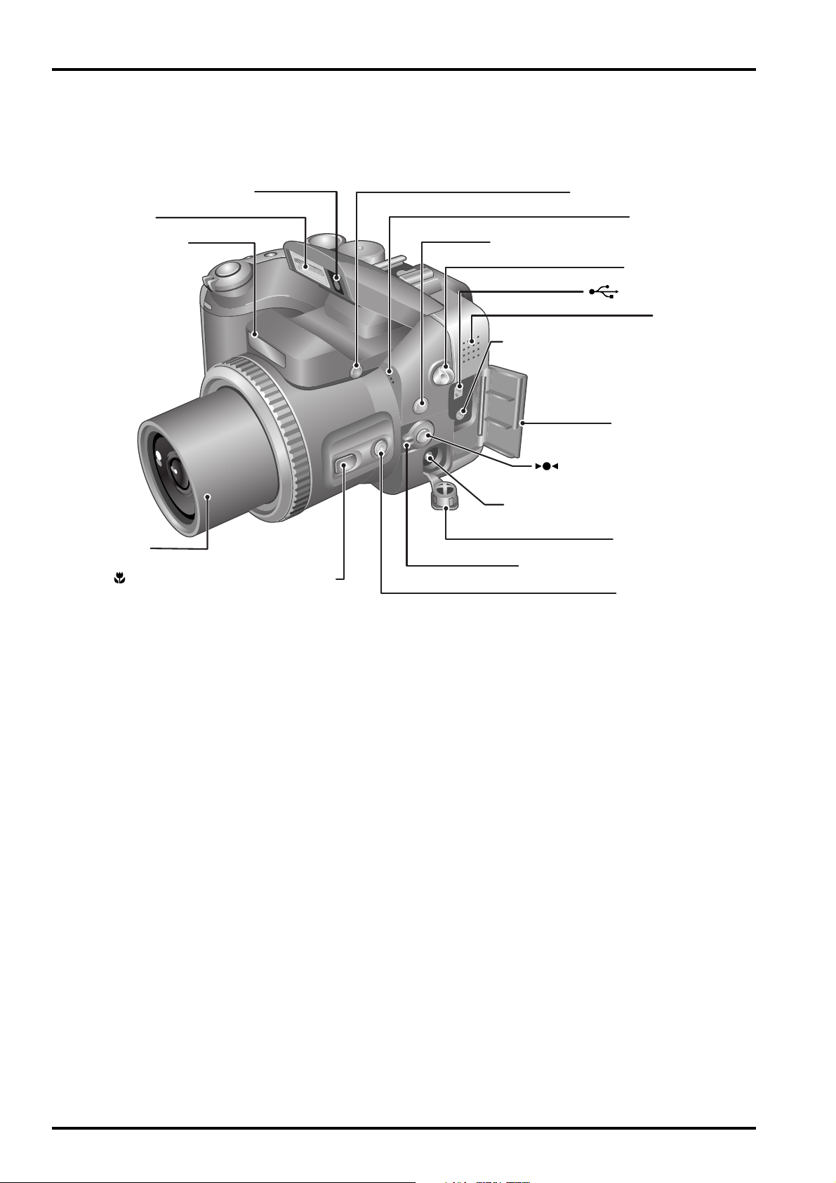
1-3. Names of External Components
Mode dial
Command dial
Continuous
shooting button
Exposure
compensation
button
Flash button
Shutter button
Power switch
Self-timer lamp
Hot shoe
Focusing ring
Strap mount
SmartMedia slot
Zoom button
AE-L (AE lock) button
BACK button
DISP button
Viewfinder (EVF)
Diopter adjustment dial
(Focus Check) button
Slot cover
MENU/OK button
4-direction ( ) button
Battery cover
LCD monitor
Indicator lamp
EVF/LCD (viewfinder/
monitor) button
Microdrive slot
Microdrive eject button
Tripod mount
8
FinePix S602 ZOOM SERVICE MANUAL
1. Specifications
Flash pop-up button
(One-touch AF) button
SHIFT button
(USB) socket
Speaker
Microphone
A/V OUT (Audio/visual output)
socket
DC IN 5V (power input) socket
Terminal cover
Focus mode selector switch
Terminal cover
INFO (information check) button
Strap mount
Lens
Macro (close-up photography)
button
Flash control sensor
Flash
AF sensor
9
FinePix S602 ZOOM SERVICE MANUAL
2. Disassembly
2. Disassembly
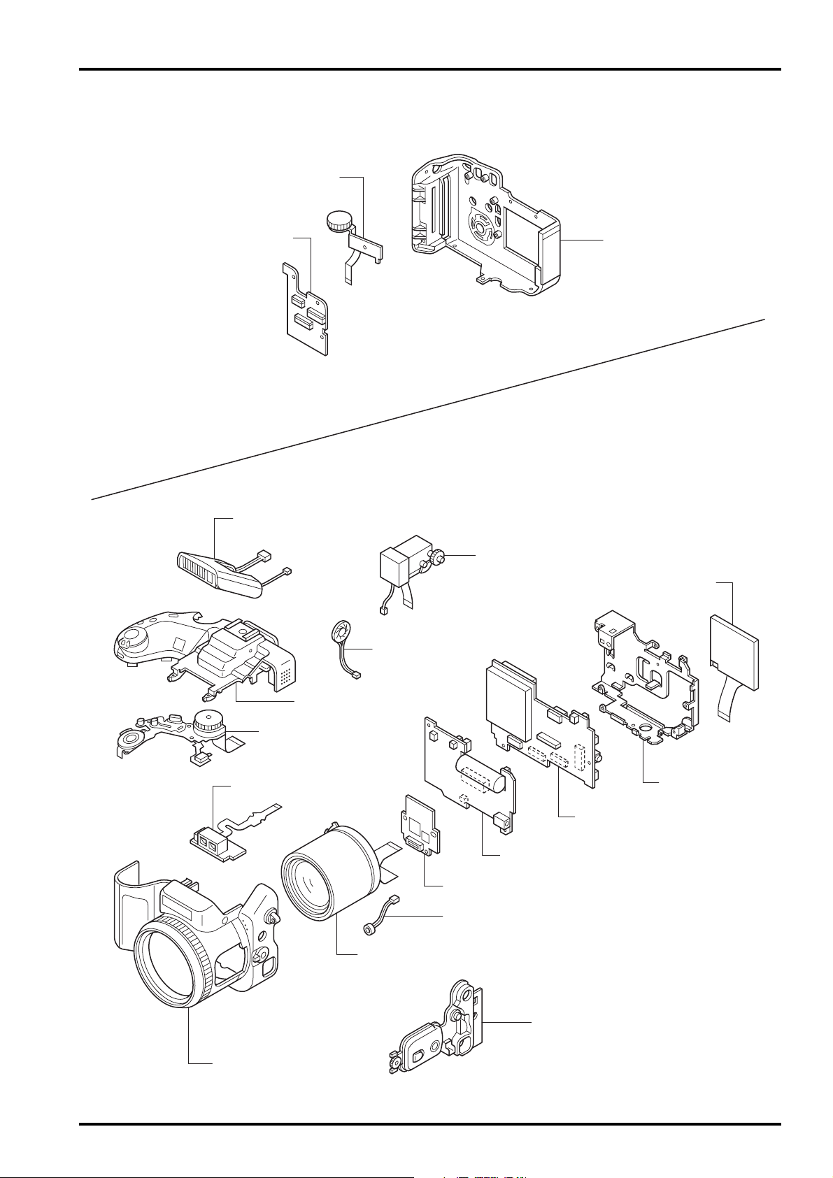
2-1. Names of Internal Components
R CABI ASSY
C DIAL UNIT
KEY PWB ASSY
MAIN PWB ASSY
DCST PWB ASSY
EVF CONST
SPEAKER ASSY
TOP CABI ASSY
MODE DIAL UNIT
AF SENSOR UNIT
LCD ASSY
ST ASSY CONST
CAM PWB ASSY
MIC ASSY
LENS CONST
SIDE MODULE UNIT
F CABI ASSY
LCD FRAME
10
FinePix S602 ZOOM SERVICE MANUAL
2. Disassembly
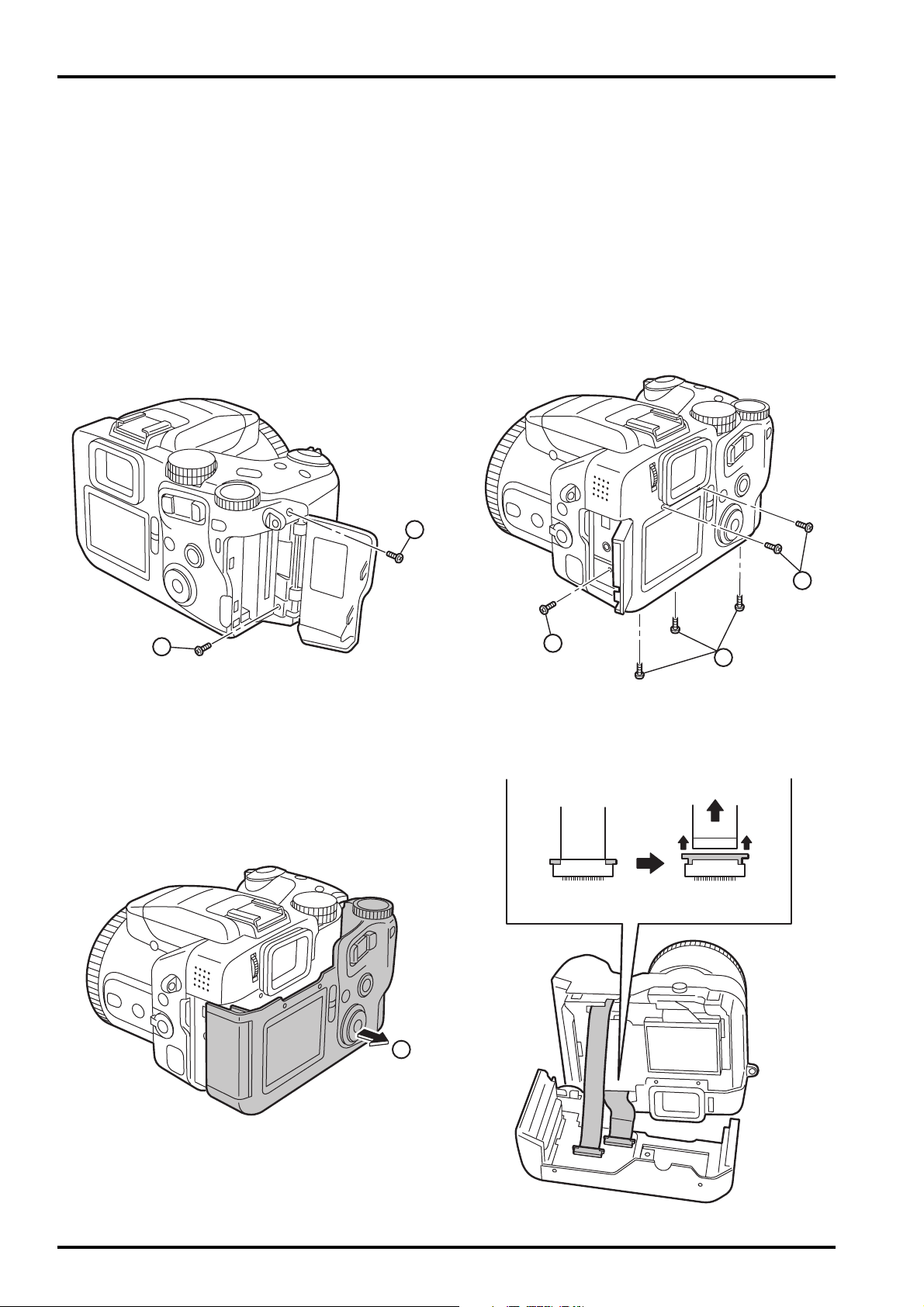
2-2. How to remove R CABI CONST
[Procedure]
1. Remove screw (M1.7x8.0).
2. Remove screw (M1.7x5.5).
3. Remove six screws (M1.7x5.0).
4. Remove R CABI CONST in the direction of the arrow.
5. Remove FFC(x2).
(The undermentioned refer to how to remove the connector. )
[Assembly procedure]
Assemble it according to a reverse procedure.
1
2
3
3
3
4

11
FinePix S602 ZOOM SERVICE MANUAL
2. Disassembly
2-3. Decomposition of R CABI CONST
[Procedure]
1. Remove FFC from KEY PWB ASSY.
2. Remove screw (M1.7x4.0).
3. Remove C DIAL UNIT in the direction of the arrow.
4. Push STRAP L from the direction of the arrow and remove.
5. Remove three screws (M1.7x4.0).
6. Remove KEY PWB ASSY.
7. Remove OK BUTTON, REAR BUTTON, ZOOM BUTTOM, and LED LENS.
[Assembly procedure]
Assemble it according to a reverse procedure.
1
2
3
4
6
5
7
7
7
7
12
FinePix S602 ZOOM SERVICE MANUAL
2. Disassembly
2-4. How to remove LCD ASSY
[Procedure]
1. Detach the undermentioned parts.
R CABI CONST
2. Put tweezers etc. in the LCD FRAME hook on LCD right side and remove LCD ASSY from LCD FRAME.
3. Remove the lock of the connector of MAIN PWB ASSY, and remove FFC from LCD ASSY.
4. Remove Wire Harness connected with LCD ASSY.
[Assembly procedure]
Assemble it according to a reverse procedure.
[Notes of assembly]
Process FFC/Wire Harness between LCD FRAME and MAIN PWB ASSY.
1
2
3

13
FinePix S602 ZOOM SERVICE MANUAL
2. Disassembly
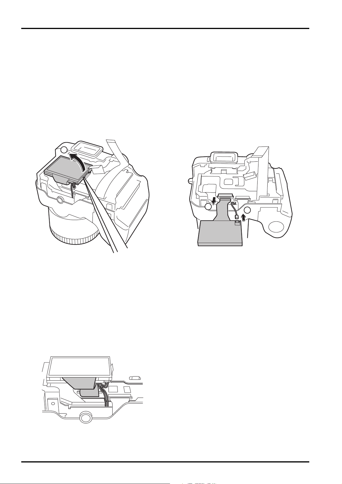
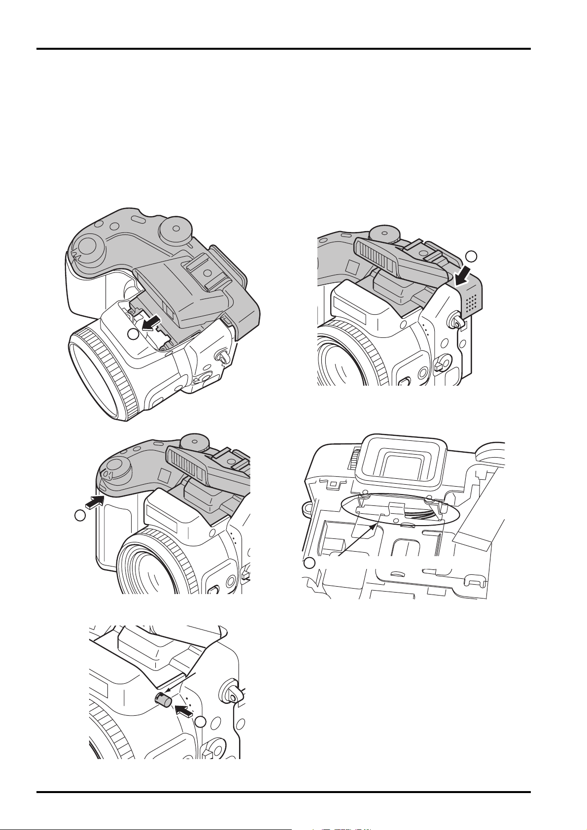
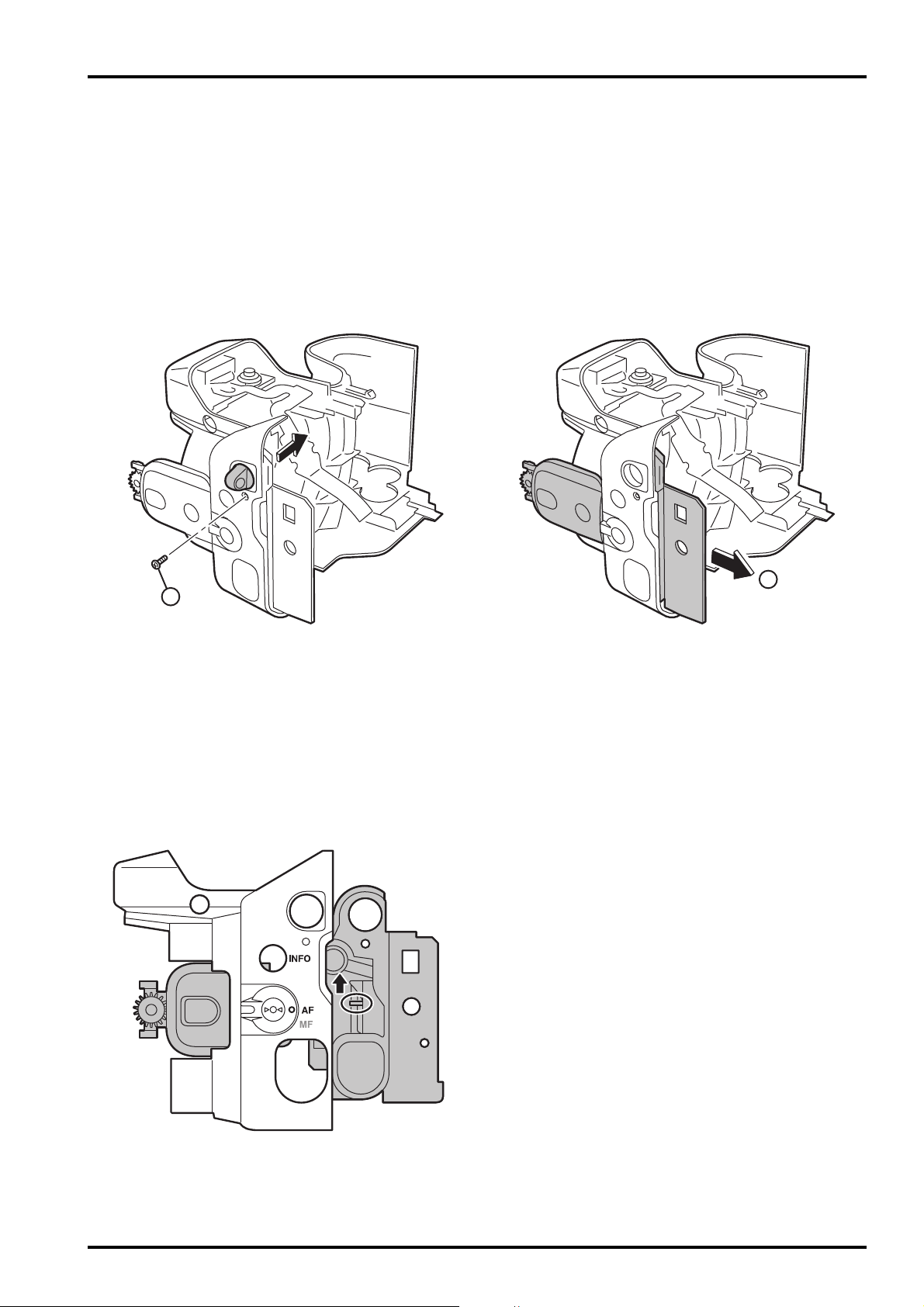
2-5. How to remove TOP CABI CONST
[Procedure]
1. Detach the undermentioned parts.
R CABI CONST, LCD ASSY
2. Push ST BUTTON, and improve the flash in pop.
3. Detach AF PLATE to the space between AF PLATE and F CABI CONST with a needle etc.
Note that neither AF PLATE nor F CABI CONST are damaged.
Do not stab the finger etc. enough when you use the needle.
4. Remove the hook of ST BUTTON and remove ST BUTTON from the main body by using a minus driver.
Do not lose because CSP(ST BUTTON) comes off together when ST BUTTON is detached.
5. Remove two screws (M1.7x5.5).
3
4
5

14
FinePix S602 ZOOM SERVICE MANUAL
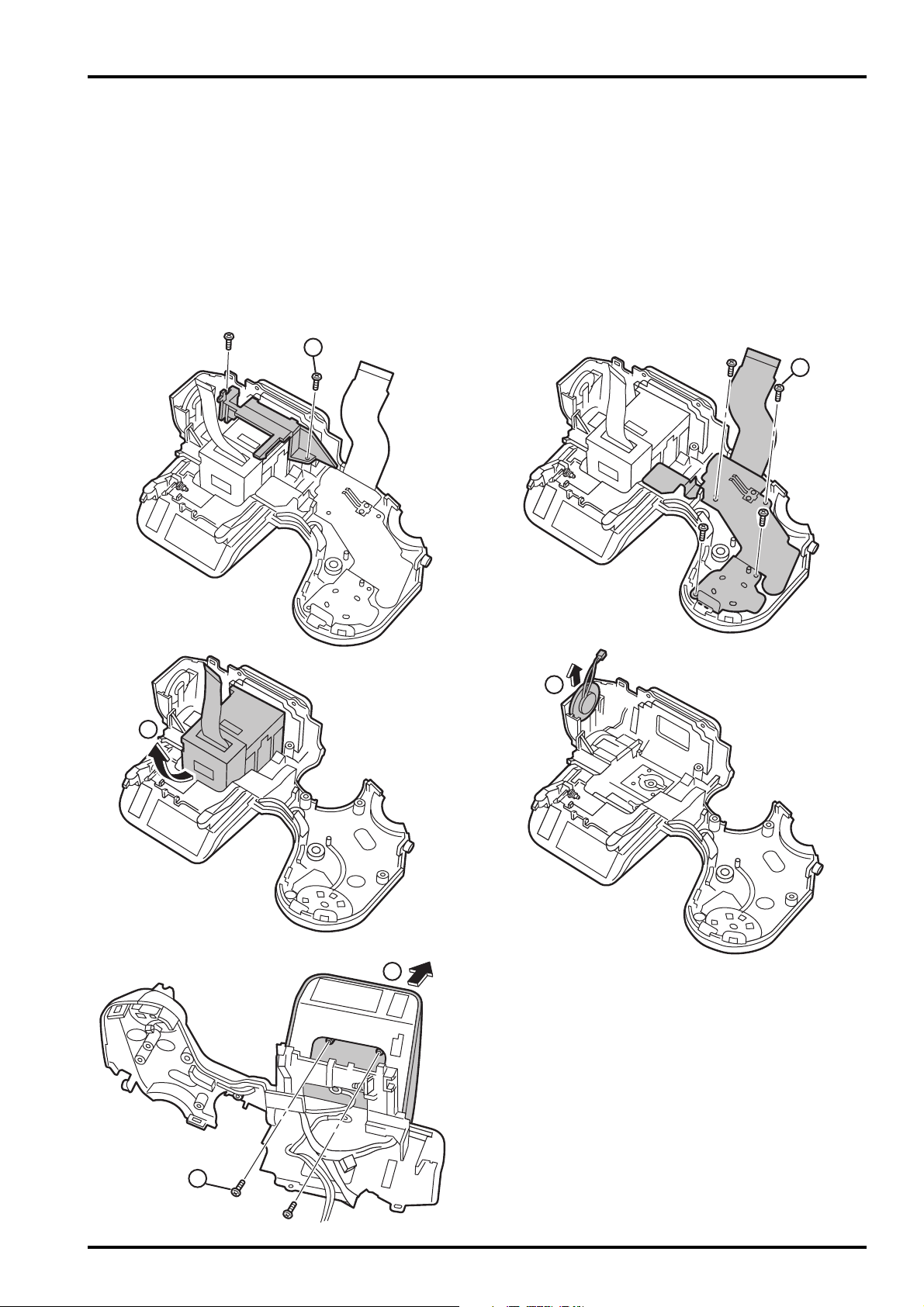
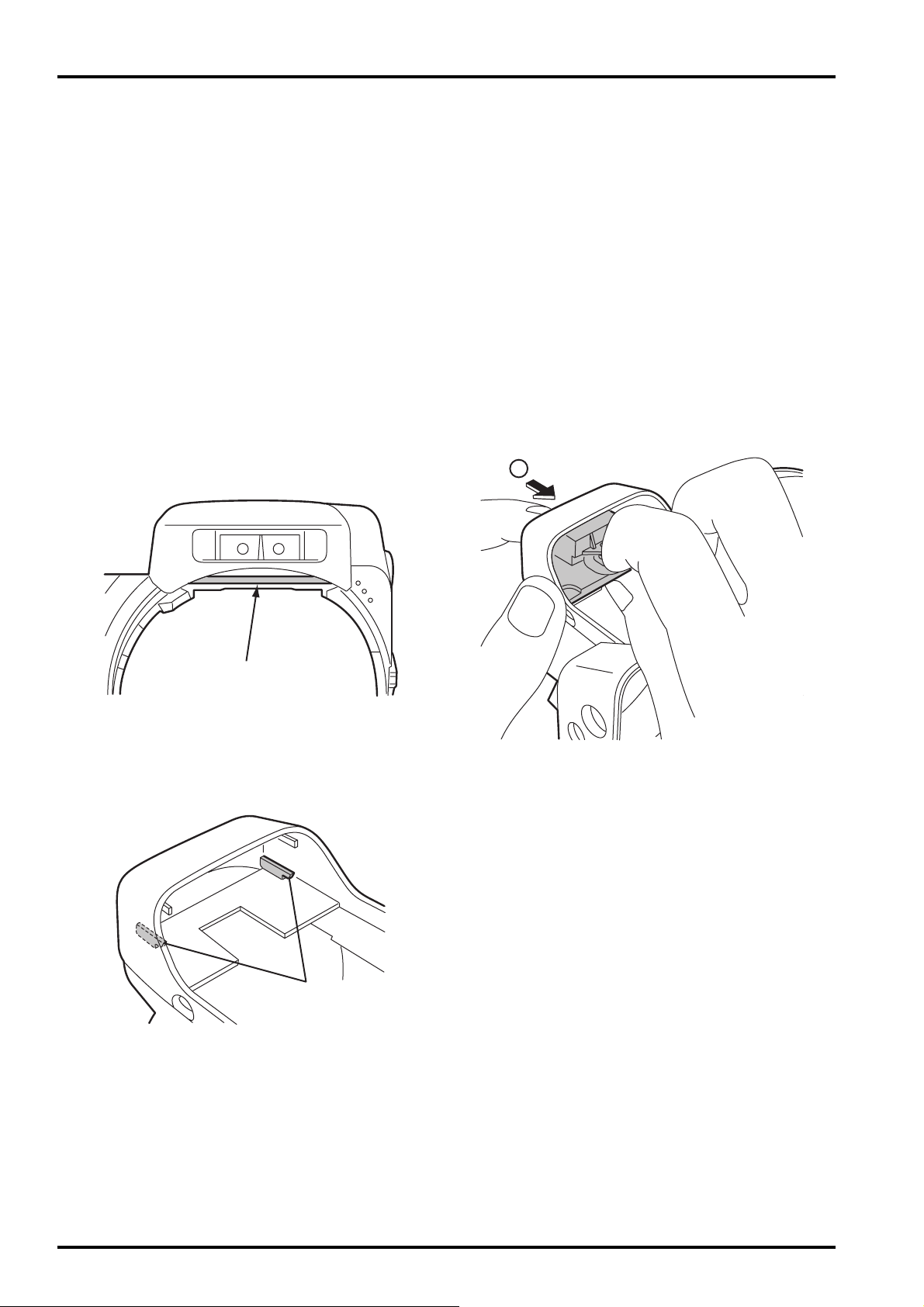
2. Disassembly
6. Remove the speaker side of TOP CABI CONST in the direction of the arrow.
7. Lift the SHUTTER BUTTON side of TOP CABI CONST in the direction of the arrow and remove.
8. Remove from the main body while pulling TOP CABI CONST backward.
6
7
8
15
FinePix S602 ZOOM SERVICE MANUAL
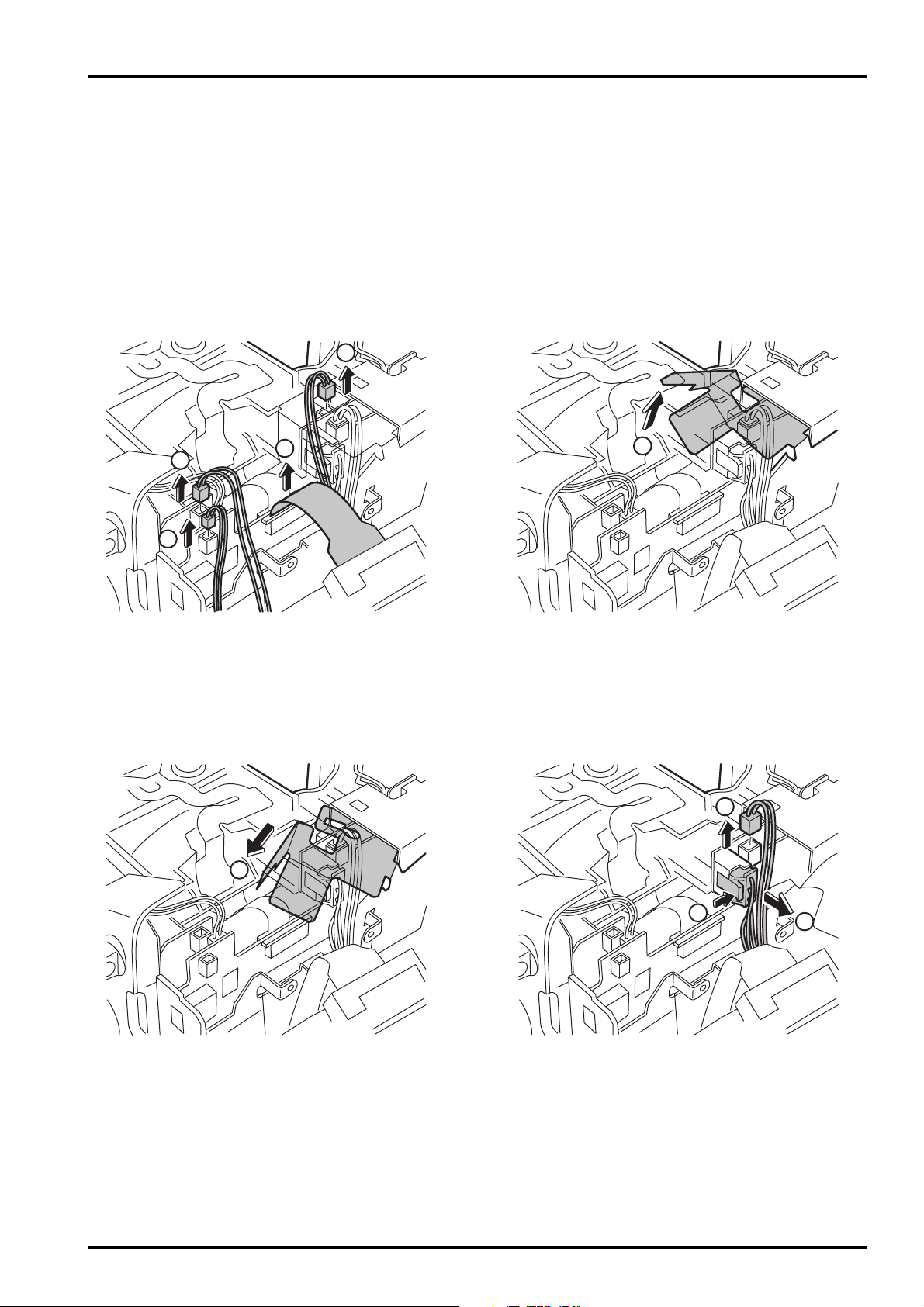
2. Disassembly
9. Remove Wire Harness (3) from TOP CABI CONST and FFC (1).
10. Pull out SHEET FRAME from LCD FRAME.
11. Remove Wire Harness (2).
There is no dread of the electric shock and do not touch the terminal when you remove Wire Harness
for the flash from the substrate.
9
9
9
9
10
11
11
11
10
16
FinePix S602 ZOOM SERVICE MANUAL
2. Disassembly
[Assembly procedure]
Assemble it according to a reverse procedure.
1. Combine intuition on the tip of the AF sensor when you connect all Wire Harness with FFC.
2. Combine the speaker side of TOP CABI CONST in intuition in the hook of F CABI CONST.
3. Combine the grip part in intuition surely. At this time, confirm grip rubber is turned over and not transformed.
4. Confirm TOP CABI CONST and confirm Wire Harness has been installed after it clings surely in SHEET FRAME.
5. Note that it is at the top and bottom (The gate is the above) in ST BUTTON at assembly.
2
3
Note the scissors crowding of Wire Harness.
4
Gate
5
1
17
FinePix S602 ZOOM SERVICE MANUAL
2. Disassembly
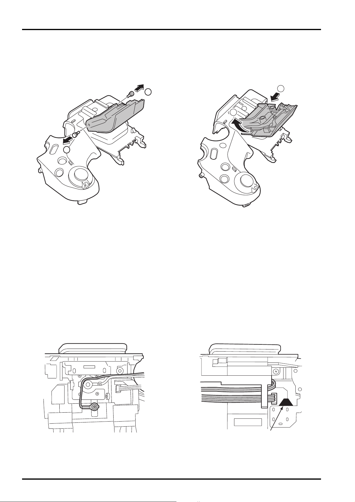
2-6. Decomposition of TOP CABI CONST
[Procedure]
1. Remove two screws (M1.7x4.0), and remove HOLDER EVF.
2. Remove four screws (M1.7x4.0), and remove MODE DIAL UNIT.
3. Remove EVF CONST.
4. Remove SPEAKER ASSY.
5. Remove two screws (M1.7x4.0), and remove ST TOP.
1
2
3
4
5
5
18
FinePix S602 ZOOM SERVICE MANUAL
2. Disassembly
6
6
7
7
ࠬ࠻ࡠࡏࡐ࠶ࡊࠕ࠶ࡊᬌ59
6. Remove ST SHUFT(x2).
7. Lift while pressing ST ASSY CONST against the SHUTTER BUTTON side and remove.
[Assembly procedure]
Assemble it according to a reverse procedure.
[Notes of assembly]
Note the taking turning of the flash hiss harness.
Pass the flash hiss harness and the flash harness through the fingernail of HOLDER EVF.
Do not float on the flash hiss harness and the flash harness.
<harness> do not interfere in flash pop up detection SW.
Flash pop up detection SW
19
FinePix S602 ZOOM SERVICE MANUAL
2. Disassembly
2
2
2
2
2
2
A
B
3
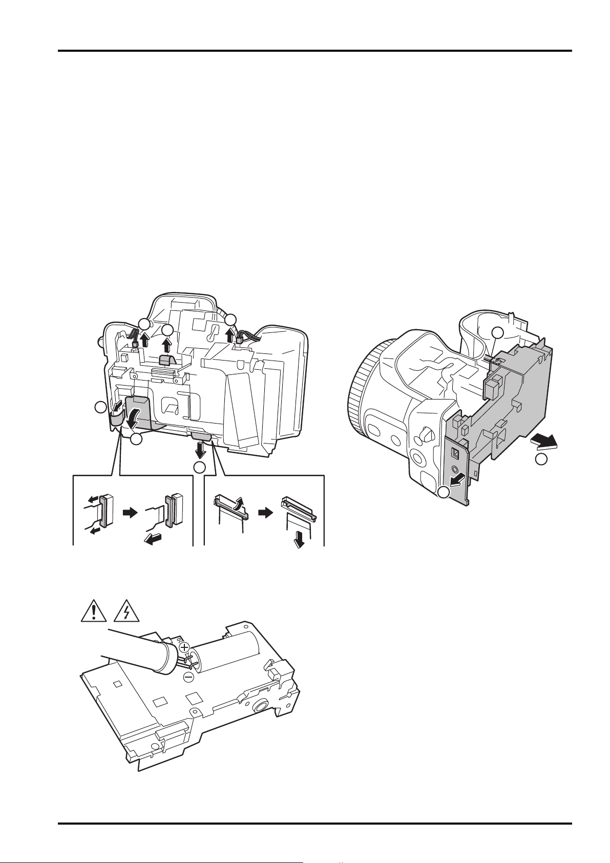
2-7. How to remove LCD FRAME CONST
[Procedure]
1. Detach the undermentioned parts.
R CABI CONST, LCD ASSY, ST PLATE, ST BUTTON, TOP CABI CONST
2. Remove FFC Wire Haness (4)(2).
3. Remove main body A and part B, and remove LCD FRAME CONST.
4. Discharge electricity from the main capacitor of DCST PWB ASSY.
[Assembly procedure]
Assemble it according to a reverse procedure.
20
FinePix S602 ZOOM SERVICE MANUAL
2. Disassembly
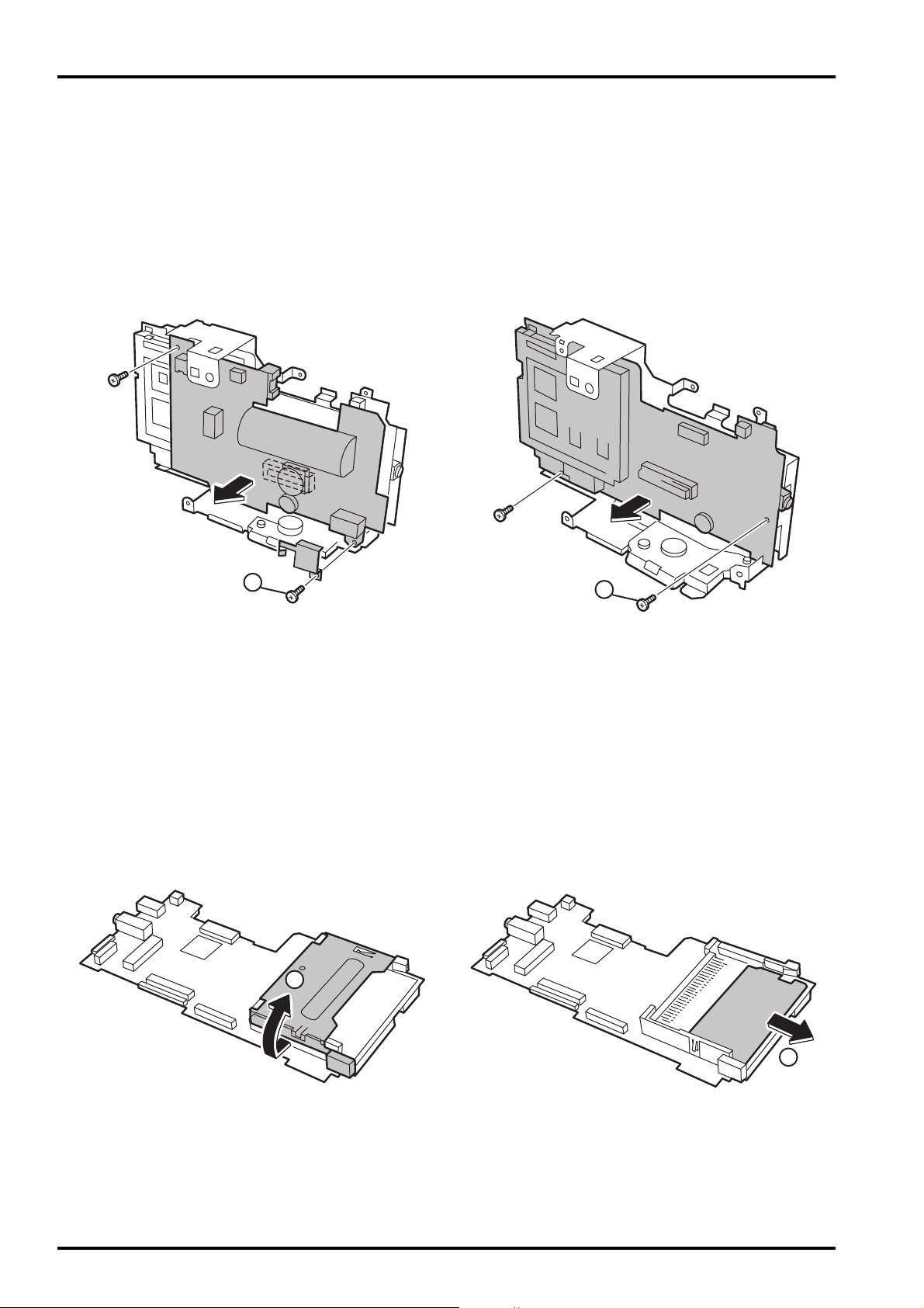
2-8. Decomposition of LCD FRAME CONST
[Procedure]
Confirm the main capacitor of DCST PWB ASSY has been discharged without fail before work is started.
1. Remove two screws (M1.7x3.0), and remove CONTACT PLT and DCST PWB ASSY.
2. Remove two screws (M1.7x3.0), and remove MAIN PWB ASSY.
[Assembly procedure]
Assemble it according to a reverse procedure.
2-9. Decomposition of MAIN PWB ASY
[Procedure]
1. Remove EJECTER in the direction of the arrow.
2. Remove SHEET CF.
[Assembly procedure]
Assemble it according to a reverse procedure.
1
2
1
2

21
FinePix S602 ZOOM SERVICE MANUAL
2. Disassembly
2-10. How to remove SHEET FRAME
[Procedure]
1. Remove SHEET FRAME from LCD FRAME.
[Assembly procedure]
Assemble it according to a reverse procedure.
[Notes of assembly]
Note the damage of SHEET FRAME when you install SHEET FRAME in LCD FRAME.
2-11. How to remove BATTERY LID
[Procedure]
1. Lift the hook of BATTERY LID, and remove BATTERY LID.
[Assembly procedure]
Assemble it according to a reverse procedure.
2
22
FinePix S602 ZOOM SERVICE MANUAL
2. Disassembly
2-12. How to remove BATTERY HOLDER UNIT
[Procedure]
1. Detach the undermentioned parts.
R CABI CONST, LCD ASSY, ST PLATE, ST BUTTON, TOP CABI CONST, LCD FRAME CONST
BATTERY LID
2. Remove screw (M1.7x5.0).
3. Remove BATTERY HOLDER UNIT from the main body while opening the main body grip part.
[Assembly procedure]
Assemble it according to a reverse procedure.
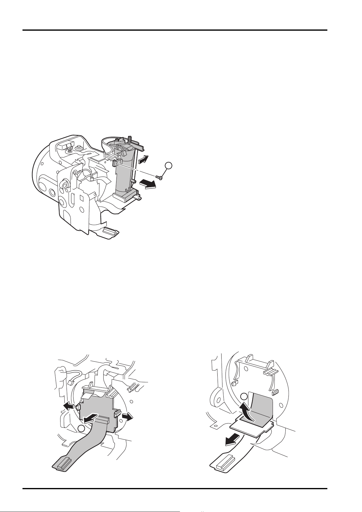
2-13. How to remove CAM PWB ASSY
[Procedure]
1. Detach the undermentioned parts.
R CABI CONST, LCD ASSY, ST PLATE, ST BUTTON, TOP CABI CONST, LCD FRAME CONST
2. Open the hook of LENS FRAME, and remove CAM PWB ASSY in the direction of the arrow.
3. Remove FPC from LENS CONST, and remove CAM PWB ASSY from the main body.
[Assembly procedure]
Assemble it according to a reverse procedure.
2
2
3
23
FinePix S602 ZOOM SERVICE MANUAL
2. Disassembly
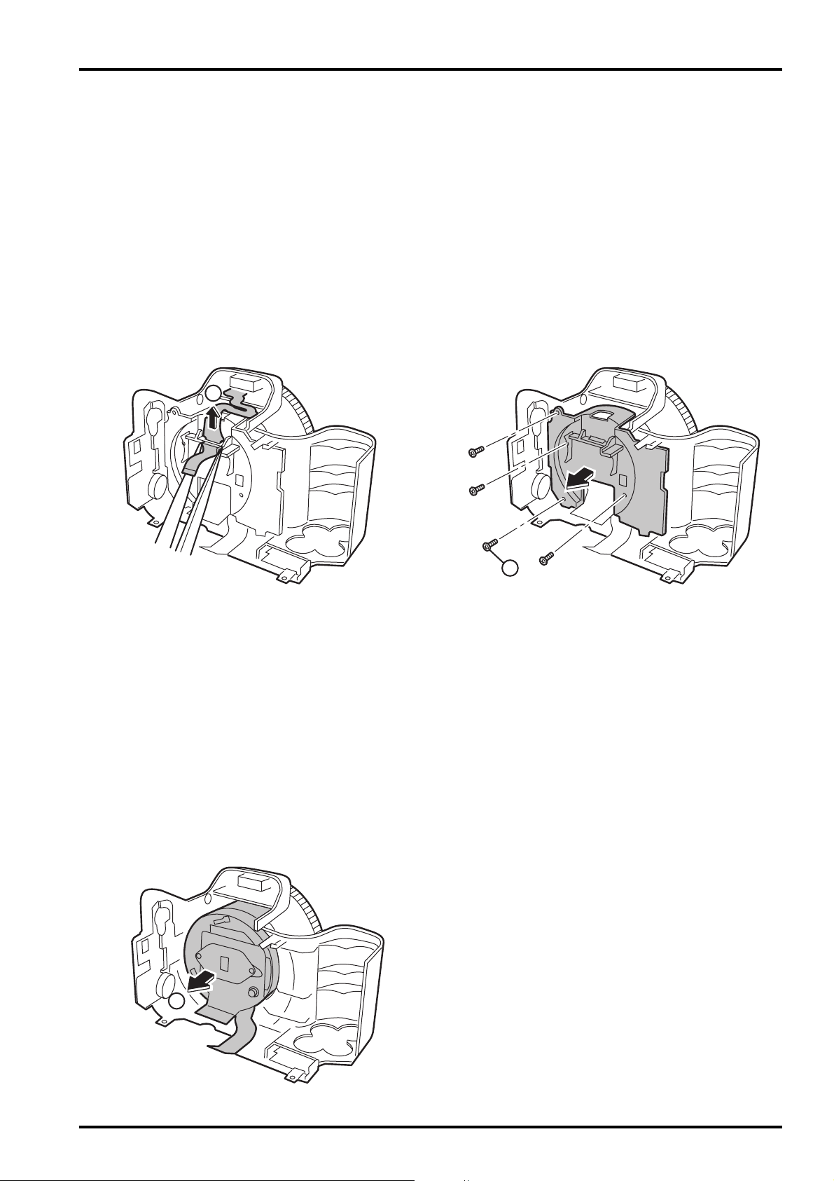
2-14. How to remove LENS FRAME
[Procedure]
1. Detach the undermentioned parts.
R CABI CONST, LCD ASSY, ST PLATE, ST BUTTON, TOP CABI CONST, LCD FRAME CONST
BATTERY LID, BATTERY HOLDER UNIT, CAM PWB ASSY
2. Remove FFC from LENS FRAME.
3. Remove screw (M1.7x5.0), and remove LENS FRAME from the main body.
[Assembly procedure]
Assemble it according to a reverse procedure.
[Notes of assembly]
Do so as not to cut FFC adding impossible power when you build FFC into LENS FRAME noting it.
2-15. How to remove LENS CONST
[Procedure]
1. Detach the undermentioned parts.
R CABI CONST, LCD ASSY, ST PLATE, ST BUTTON, TOP CABI CONST, LCD FRAME CONST
BATTERY LID, BATTERY HOLDER UNIT, CAM PWB ASSY, LENS FRAME
2. Remove LENS CONST from F CABI UNIT.
2
3
2
24
FinePix S602 ZOOM SERVICE MANUAL
2. Disassembly
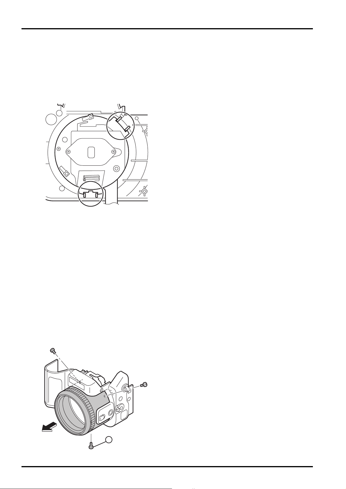
2-16. How to remove LENS CABI ASSY
[Procedure]
1. Detach the undermentioned parts.
R CABI CONST, LCD ASSY, ST PLATE, ST BUTTON, TOP CABI CONST, LCD FRAME CONST
BATTERY LID, BATTERY HOLDER UNIT, CAM PWB ASSY, LENS FRAME, LENS CONST
2. Remove three screws (M1.7X3.5), and remove LENS CABI ASSY.
[Assembly procedure]
Assemble it according to a reverse procedure.
[Attention]
Because the torque is managed as for FOCUS RING of LENS CABI ASSY, it is not possible to decompose.
2
[Assembly procedure]
Assemble it according to a reverse procedure.
[Notes of assembly]
Make the cutting lack of the rib and LENS CONST of F CABI CONST combined in intuition,
and build it in when you build in LENS CONST.
25
FinePix S602 ZOOM SERVICE MANUAL
2. Disassembly
2-17. How to remove SIDE MODULE UNIT
[Procedure]
1. Detach the undermentioned parts.
R CABI CONST, LCD ASSY, ST PLATE, ST BUTTON, TOP CABI CONST, LCD FRAME CONST
BATTERY LID, BATTERY HOLDER UNIT, CAM PWB ASSY, LENS FRAME, LENS CONST
LENS CABI ASSY
2. Remove screw (M1.7x5.0), and remove STRAP R.
3. Remove SIDE MODILE UNIT from F CABI ASSY.
2
3
[Assembly procedure]
Assemble it according to a reverse procedure.
[Notes of assembly]
Match and build in the position of the FOCUS switch lever of FOCUS switch SW and F CABI ASSY
of SIDE MODILE UNIT.
26
FinePix S602 ZOOM SERVICE MANUAL
2. Disassembly
2-18. How to remove AF SENSOR UNIT
[Procedure]
1. Detach the undermentioned parts.
R CABI CONST, LCD ASSY, ST PLATE, ST BUTTON, TOP CABI CONST, LCD FRAME CONST
BATTERY LID, BATTERY HOLDER UNIT, CAM PWB ASSY, LENS FRAME, LENS CONST
LENS CABI ASSY
2. Remove AF SENSOR UNIT in the direction of the arrow while pushing the front side part of AF SENSOR UNIT
by the finger.
[Assembly procedure]
Assemble it according to a reverse procedure.
[Attention]
Replace F CABI ASSY when guide ditch part F CABI ASSY is damaged when AF SENSOR UNIT is detached.
2
AF SENSOR UNIT
ࠟࠗ࠼Ḵㇱ
Guide ditch part

FinePix S602 ZOOM SERVICE MANUAL
27
3. Schematic
3. Schematic
3-1.Cautions
<Caution when replaceing chip (leadless) parts.>
* Do not re-use the removed parts, but use new parts.
Be careful that the negativ side of the tantalum capacitors are susceptible to heat.
* Voltage indications are omitted for capacitors other than chemical and tantalum capacitors with a dielectric strength
of 50 V or less.
* Chip resistors without indication are 1/10 W.
* k=1000
, M=1000 k
* Variable resistors and semi-variable resistor are abbreviated the specification of B characteristic.
3-2.Overview of Functions of Each Circuit
Board Name Block name Function
LENS CONST CCD BLOCK CCD output
CAM PWB ASSY CAM BLOCK Analog to digital conversion of CCD output (IC102)
CCD driver (IC100)
MAIN PWB ASSY PROCESS BLOCK Video signal processing (IC210)
USB communication (IC210)
System control (IC210)
MOTOR BLOCK Shutter/Iris/AF/Zoom driver (IC602)
POWER ON BLOCK Power control (IC302)
EVF BLOCK EVF control (IC405)
LCD BLOCK LCD control (IC404)
AUDIO BLOCK Audio signal processing (IC500)
DCST PWB ASSY DC/DC BLOCK Each power supply generation (IC902)
KEY PWB ASSY KEY BLOCK Operation SW(TELE/WIDE,EVF/LCD,MENU/OK,etc.)
SIDE MODULE UNIT SIDE KEY BLOCK Operation SW(MACRO,CUSTOM,INFO,AF/MF,OPAF)
MODE DIAL UNIT MODE BLOCK Operation SW(OFF/CAM/PB,S1/S2,MODE,ETC.)
ST ASSY CONST STROBO BLOCK Flash luminescence
 Loading...