


 Loading...
FUJI COMPUTED RADIOGRAPHY
FCR CAPSULA X/FCR CARBON X
CR-IR 357
Service Manual
The relationship between mR (milliroentgen), which is the unit of radiation, and μC/kg (micro-coulomb/kilogram), which is the SI derived unit of radiation, is as follows.
1 mR = 0.258μC/kg
FCR ® is a registered trademark of Fuji Photo Film Co., Ltd.
<No part of this manual may be reproduced or transmitted.>
Copyright © 2005 by Fuji Photo Film Co., Ltd.
All rights reserved. No part of this publication may be reproduced, stored in a retrieval system, or transmitted in any form or by means, electronic, mechanical, photocopying, recording or otherwise, without the prior written permission of Fuji Photo Film Co., Ltd. Miyanodai Technology Development Center.
Document No. 014-204-01A 1st Edition - Aug. 15, 2005 Revised EditionNov. 10, 2005
Fuji Photo Film Co., Ltd.
Printed in Japan
BLANK PAGE

0.1
1.Handling of This Manual
1.1About This Manual
Scope
This Service Manual is applicable to Fuji Computed Radiography CR-IR 357. The machine is categorized as Class 1 according to IEC classification.
Notation of Unit Symbols
For notation of unit symbols, metric units set forth in the International Systems of Units (SI) are used, as a rule. However, metric units that are allowed in the Measurement Law, not in the SI, are used in some cases.
1.2Precautions for Handling of This Manual
1.Fuji Photo Film Co., Ltd reserves all rights related to this manual.
2.This manual should be accessible only to technical service personnel authorized by Fuji Photo Film Co., Ltd.
3.Since this manual contains confidential information of Fuji Photo Film Co., Ltd, such as the internal structure of the product, appropriate measures should be taken to prevent illegal or inappropriate disclosure and/or use of this manual.
4.The following conducts are prohibited without prior written approval of Fuji Photo Film Co., Ltd.:
-Copy or transcribe a whole or part of the contents of this manual
-Disclose, furnish, lend, and/or transfer a whole or part of the contents of this manual to persons other than the afore-described technical service personnel.
-Use a whole or part of the contents of this manual for purposes other than technical servicing of the product.
5.Portions of the descriptions in this manual may be revised due to improvements on the product.
1.3About Notation in the Manual
Notation of cautions, warnings, etc.
The notation formats of "warning", "caution", "Instruction", "note", and "reference" are shown below.
 WARNING
Used when death or serious injury may occur if the instruction is not observed.
 CAUTION
Used when minor or medium levels of physical injury may be incurred if the instruction is not observed.
Also used when the machine may suffer serious trouble (such as unrecoverable or difficult-to-recover trouble).
INSTRUCTION
Used when the machine may suffer damage, or any failure or malfunction may occur, if the instruction is not observed.
NOTE
Used to indicate the matters that need attention during steps of the procedure.
 REFERENCE
Used to indicate terminology or supplemental explanations.
Indication of Refer To
The " " mark is used to indicate the chapter or section you should refer to. Its format is as indicated below.
 {MC:5.1_Cassette Set Unit}
Notation in the Manual
In this Service Manual, the CR-IR 357 is sometimes denoted simply as the RU (Reader Unit), and the CR-IR346/348CL as the CR Console.
014-204-01E 11.10.2005 FM4750
CR-IR 357 Service Manual |
0.1 |

0.2
Notation of Symbols
-Check/Adjustment indicator:Indicates that it is necessary to check or adjust the
|
installation location when the part or component |
CHECK1 |
removed is to be reinstalled. |
This indicator is placed in the illustration that depicts |
|
|
the procedures for removing the parts and components. |
|
When you see this indicator, refer to its relevant |
|
" Check/Adjustment Procedures." |
- Half-punch indicator: |
Indicates that it is necessary to align the half-punches |
|
when installing the parts or components. |
|
However, it is not indicated for the half-punches for |
|
improving ease of assembly or preventing erroneous |
|
assembly procedures. |
Servicing Instruments and Tools That Require Inspection/Calibration
The machine should be installed and serviced by use of servicing instruments and tools that have been inspected and calibrated as appropriate.
If the machine were serviced using servicing instruments and tools that have not been inspected and calibrated, proper performance of the machine could not be guaranteed.
Servicing instruments and tools that require inspection/calibration are as listed below. Inspection/calibration procedures should be performed in accordance with the inspection/ calibration manuals described in the ECN Information.
Instruments and tools that require inspection/calibration
Name |
Inspection |
Calibration |
Servicing instrument inspection/ |
|
calibration manual No. |
||||
|
|
|
||
|
|
|
|
|
Dosimeter |
- |
|
FF-001 |
|
|
|
|
|
|
Steel rule (150mm) |
|
- |
FF-005 |
|
|
|
|
|
|
Steel rule (300mm) |
|
- |
FF-006 |
|
|
|
|
|
|
Digital tester |
|
|
FF-012 |
|
|
|
|
|
|
Calipers |
( ) |
- |
FF-015 |
|
|
|
|
|
: A block gauge for use in inspection requires calibration.
014-204-01E 11.10.2005 FM4750
CR-IR 357 Service Manual |
0.2 |

Contents Safety Precautions |
0.3 |
CR-IR 357 Service Manual - Contents
Safety Precaution
1. Safety Precautions........................................... |
Safety-1 |
|
1.1 |
General Precautions ............................................................... |
Safety-1 |
1.2 |
Precautions Against Laser Radiation....................................... |
Safety-2 |
1.3 |
Precautions on Patient Environment........................................ |
Safety-2 |
1.4 |
Precautions in Retaining the Machine...................................... |
Safety-3 |
1.5 |
Notes on Supporter Use.......................................................... |
Safety-3 |
2. Labels................................................................ |
Safety-4 |
||
2.1 |
Laser Precaution Labels ......................................................... |
Safety-4 |
|
2.1.1 Laser Precaution Label Attachment Locations................................ |
Safety-4 |
||
2.1.2 List of Laser Precaution Labels....................................................... |
Safety-5 |
||
2.2 |
Ratings Indication Labels ........................................................ |
Safety-6 |
|
2.3 |
Handling Instruction Labels and Attachment Locations............ |
Safety-7 |
|
2.3.1 |
Cassette Set Unit ............................................................................ |
Safety-7 |
|
2.3.2 |
Erasure Unit .................................................................................... |
Safety-7 |
|
2.3.3 |
Side-Positioning Conveyor Unit....................................................... |
Safety-7 |
|
2.3.4 |
Subscanning Unit ............................................................................ |
Safety-8 |
|
2.3.5 |
Light-Collecting Guide..................................................................... |
Safety-8 |
|
2.3.6 |
Scanning Optics Unit....................................................................... |
Safety-8 |
|
2.3.7 |
Covers............................................................................................. |
Safety-9 |
|
2.3.8Cassette Insertion Operation Label, Cassette Right-Justifying
|
Label................................................................................................ |
Safety-9 |
2.3.9 |
Lead Precaution Label .................................................................. |
Safety-10 |
2.3.10 |
Power Cable Caution Label........................................................... |
Safety-10 |
3. Protective Housings Against Laser |
|
|
Exposure.......................................................... |
Safety-11 |
|
4. |
CLASSIFICATION ............................................ |
Safety-11 |
|
5. |
Cautions on Electromagnetic Waves ........... |
Safety-12 |
|
|
5.1 |
Electromagnetic Compatibility (EMC) .................................... |
Safety-12 |
|
5.2 |
Further information for IEC60601-1-2:2001 ........................... |
Safety-12 |
014-204-01E 11.10.2005 FM4750
CR-IR 357 Service Manual |
0.3 |

Contents Product Specifications |
0.4 |
Product Specifications
1. Specifications of Machine .................................. |
Spec-1 |
|
1.1 |
Product Code............................................................................ |
Spec-1 |
1.2 |
Available IP Sizes and Types .................................................... |
Spec-1 |
1.3 |
Available Cassette Types and Sizes.......................................... |
Spec-1 |
1.4 |
List of Optional Items ................................................................ |
Spec-1 |
1.5 |
Product Specifications .............................................................. |
Spec-2 |
1.6 |
Dimensions, Weight, and Center of Gravity............................... |
Spec-2 |
1.7 |
Moving Means for the Machine ................................................. |
Spec-3 |
1.8 |
Retaining Means for the Machine.............................................. |
Spec-3 |
1.8.1 Retaining the Machine on Adjustable Feet........................................ |
Spec-3 |
|
1.8.2 Retaining the Machine by Use of Anti-Topple Retainer..................... |
Spec-4 |
|
1.9 |
Environmental Conditions.......................................................... |
Spec-5 |
1.10 |
Electrical Specifications ............................................................ |
Spec-5 |
1.11 |
Servicing Space........................................................................ |
Spec-6 |
1.12 |
Installation Space...................................................................... |
Spec-6 |
1.12.1 For Fixing by Adjustable Feet............................................................ |
Spec-6 |
|
1.12.2 Retaining the Machine by the Anti-Topple Retainer .......................... |
Spec-7 |
|
1.12.3 Installing the Machine where the Long Cassette Is to Be Used........ |
Spec-7 |
|
1.12.4 Using the Supporter .......................................................................... |
Spec-8 |
|
1.13 |
Disposal.................................................................................... |
Spec-9 |
1.13.1 Disposal of IP .................................................................................... |
Spec-9 |
|
014-204-01E 11.10.2005 FM4750
CR-IR 357 Service Manual |
0.4 |

Contents Machine Description (MD) |
0.5 |
Machine Description (MD)
1. Machine Overview.................................................. |
MD-1 |
||
1.1 |
Features ...................................................................................... |
MD-1 |
|
1.2 |
System Configuration................................................................... |
MD-1 |
|
1.3 |
Overall Machine Configuration and Component Names ............... |
MD-2 |
|
1.3.1 External View of Machine.................................................................... |
MD-2 |
||
1.3.2 |
Nomenclature and Functions .............................................................. |
MD-2 |
|
1.3.3 Operation Panel Display Screen Contents.......................................... |
MD-3 |
||
1.4 |
Machine Components.................................................................. |
MD-4 |
|
1.4.1 |
Unit Locations...................................................................................... |
MD-4 |
|
1.4.2 Roller Locations and Conveyance Paths ............................................ |
MD-4 |
||
1.5 |
I/O Locations and Functional Descriptions.................................... |
MD-5 |
|
1.5.1 |
Cassette Set Unit - 1 ........................................................................... |
MD-5 |
|
1.5.2 |
Cassette Set Unit - 2 ........................................................................... |
MD-6 |
|
1.5.3 |
Cassette Set Unit - 3 ........................................................................... |
MD-7 |
|
1.5.4 |
Erasure Unit ........................................................................................ |
MD-8 |
|
1.5.5 |
Side-Positioning Conveyor Unit - 1 ..................................................... |
MD-9 |
|
1.5.6 |
Side-Positioning Conveyor Unit - 2 ................................................... |
MD-10 |
|
1.5.7 |
Subscanning Unit ............................................................................... |
MD-11 |
|
1.5.8 |
Housing ............................................................................................. |
MD-12 |
|
1.6 |
Board Locations......................................................................... |
MD-13 |
|
1.6.1 |
Housing ............................................................................................. |
MD-13 |
|
1.6.2 |
Cassette Set Unit .............................................................................. |
MD-13 |
|
1.6.3 |
Erasure Unit ...................................................................................... |
MD-13 |
|
1.6.4 |
Scanning Optics Unit......................................................................... |
MD-14 |
|
1.6.5 |
Light-Collecting Unit .......................................................................... |
MD-14 |
|
1.6.6 |
Subscanning Unit .............................................................................. |
MD-14 |
|
1.7 |
System Block Diagram............................................................... |
MD-15 |
|
014-204-01E 11.10.2005 FM4750
CR-IR 357 Service Manual |
0.5 |

Contents Troubleshooting (MT) |
0.6 |
Troubleshooting (MT)
2. Error Code Table .................................................. |
MT-11 |
014-204-01E 11.10.2005 FM4750
CR-IR 357 Service Manual |
0.6 |

Contents Service Parts List (SP) |
0.7 |
Service Parts List (SP)
How to Use Service Parts List................................................................. |
SP-1 |
|
INDEX .................................................................................................... |
SP-2 |
|
01A |
COVER 1...................................................................................... |
SP-3 |
01B |
COVER 2...................................................................................... |
SP-4 |
02A |
FRAME 1...................................................................................... |
SP-5 |
02B |
FRAME 2...................................................................................... |
SP-6 |
02C |
FRAME 3...................................................................................... |
SP-7 |
03A |
CASSETTE SET UNIT 1............................................................... |
SP-8 |
03B |
CASSETTE SET UNIT 2............................................................... |
SP-9 |
03C |
CASSETTE SET UNIT 3............................................................. |
SP-10 |
03D |
CASSETTE SET UNIT 4............................................................. |
SP-11 |
03E |
CASSETTE SET UNIT 5............................................................. |
SP-12 |
03F |
CASSETTE SET UNIT 6............................................................. |
SP-13 |
03G |
CASSETTE SET UNIT 7............................................................. |
SP-14 |
03H |
CASSETTE SET UNIT 8............................................................. |
SP-15 |
03I |
CASSETTE SET UNIT 9............................................................. |
SP-16 |
03J |
CASSETTE SET UNIT 10........................................................... |
SP-17 |
03K |
CASSETTE SET UNIT 11............................................................ |
SP-18 |
03L |
CASSETTE SET UNIT 12........................................................... |
SP-19 |
03M |
CASSETTE SET UNIT 13........................................................... |
SP-20 |
03N |
CASSETTE SET UNIT 14........................................................... |
SP-21 |
04A |
ERASURE UNIT 1....................................................................... |
SP-22 |
04B |
ERASURE UNIT 2 ...................................................................... |
SP-23 |
04C |
ERASURE UNIT 3 ...................................................................... |
SP-24 |
05A |
SIDE-POSITIONING CONVEYOR 1 ........................................... |
SP-25 |
05B |
SIDE-POSITIONING CONVEYOR 2 ........................................... |
SP-26 |
05C |
SIDE-POSITIONING CONVEYOR 3 ........................................... |
SP-27 |
05D |
SIDE-POSITIONING CONVEYOR 4 ........................................... |
SP-28 |
05E |
SIDE-POSITIONING CONVEYOR 5 ........................................... |
SP-29 |
05F |
SIDE-POSITIONING CONVEYOR 6 ........................................... |
SP-30 |
05G |
SIDE-POSITIONING CONVEYOR 7 ........................................... |
SP-31 |
05H |
SIDE-POSITIONING CONVEYOR 8 ........................................... |
SP-32 |
06 |
SCANNING OPTICS UNIT.......................................................... |
SP-33 |
07 |
LIGHT-COLLECTING UNIT......................................................... |
SP-34 |
08A |
SUB SCANNING UNIT 1............................................................. |
SP-35 |
08B |
SUB SCANNING UNIT 2............................................................. |
SP-36 |
08C |
SUB SCANNING UNIT 3............................................................. |
SP-37 |
08D |
SUB SCANNING UNIT 4............................................................. |
SP-38 |
08E |
SUB SCANNING UNIT 5............................................................. |
SP-39 |
08F |
SUB SCANNING UNIT 6............................................................. |
SP-40 |
08G |
SUB SCANNING UNIT 7............................................................. |
SP-41 |
09A |
CONTROLLER 1 ........................................................................ |
SP-42 |
09B |
CONTROLLER 2 ........................................................................ |
SP-43 |
09C |
CONTROLLER 3 ........................................................................ |
SP-44 |
10 |
CABLE........................................................................................ |
SP-45 |
11 |
CIRCUIT DIAGRAM.................................................................... |
SP-46 |
12 |
PARTS NOS. SEARCH TABLE................................................... |
SP-54 |
13 |
OPTION...................................................................................... |
SP-57 |
14 |
JIG.............................................................................................. |
SP-58 |
15 |
List of Service Parts for Securing and Wiring............................... |
SP-59 |
014-204-01E 11.10.2005 FM4750
CR-IR 357 Service Manual |
0.7 |

Contents Preventive Maintenance (PM) |
0.8 |
Preventive Maintenance (PM)
1. Preventive Maintenance Program......................... |
PM-1 |
|
1.1 |
How To Use the Preventive Maintenance Volume...................... |
PM-1 |
1.2 |
Notations of Intervals................................................................. |
PM-1 |
1.3 |
Preventive Maintenance Program List ...................................... |
PM-2 |
1.3.1 Maintenance Programs for the First Year......................................... |
PM-2 |
|
1.3.2 Maintenance Programs for the Second Year ................................... |
PM-3 |
|
1.3.3 Maintenance Programs for the Third Year ....................................... |
PM-5 |
|
1.3.4 Maintenance Programs for the Fourth Year..................................... |
PM-6 |
|
1.3.5 Maintenance Programs for the Fifth Year......................................... |
PM-8 |
|
1.3.6 Maintenance Programs for the Sixth Year........................................ |
PM-9 |
|
2. Details of Maintenance Procedures.................... |
PM-11 |
|
2.1 |
Backing Up the Log................................................................. |
PM-11 |
2.2 |
Checking the Error Log............................................................ |
PM-13 |
2.3 |
Checking the Erasure Lamp Lighting Time............................... |
PM-14 |
3. Checking the Image/Conveyance....................... |
PM-15 |
|
3.1 |
Check Before Procedures ....................................................... |
PM-15 |
3.2 |
Checking the Image/Conveyance............................................ |
PM-15 |
3.3 |
Checking the Output Characters.............................................. |
PM-17 |
4. |
Pulling Out the Machine ...................................... |
PM-18 |
|
|
4.1 |
Unlocking the Retainers........................................................... |
PM-18 |
|
4.2 |
Disconnecting the Cables........................................................ |
PM-18 |
5. |
Removing the Covers .......................................... |
PM-20 |
|
|
5.1 |
Removing the Covers (1st/5th Year)....................................... |
PM-20 |
|
5.2 |
Removing the Covers (2nd/4th/6th Year)................................. |
PM-21 |
|
5.3 |
Removing the Covers (3rd Year)............................................. |
PM-24 |
6. Turning OFF the High-Voltage Switch................ |
PM-25 |
||
7. |
Cassette Set Unit.................................................. |
PM-26 |
|
|
7.1 |
Removing the Erasure Unit..................................................... |
PM-26 |
|
7.2 |
Removing the Cassette Set Unit............................................. |
PM-27 |
|
7.3 |
Preparation for Cleaning of Suction Cups ............................... |
PM-30 |
|
7.4 |
Cleaning the Suction Cups (Left-Hand)................................... |
PM-33 |
|
7.5 |
Cleaning the Suction Cups (Right-Hand)................................. |
PM-36 |
|
7.6 |
Cleaning the Rubber Rollers (Small)....................................... |
PM-39 |
|
7.7 |
Cleaning the Rubber Rollers................................................... |
PM-40 |
|
7.8 |
Installing the Components........................................................ |
PM-41 |
|
7.9 |
Cleaning the Antistatic Member and Shutter ........................... |
PM-43 |
|
7.10 |
Replacing the Dumper (Opposite Reference Side).................. |
PM-44 |
|
7.11 |
Replacing the Dumper (Reference Side)................................. |
PM-45 |
|
7.12 |
Cleaning inside the Machine and the Antistatic Member.......... |
PM-49 |
|
7.13 |
Reinstalling the Cassette Set Unit........................................... |
PM-50 |
|
7.14 |
Cleaning the Dust-Tight Cover Assembly................................ |
PM-53 |
|
7.15 |
Replacing the IP Suction Pump............................................... |
PM-56 |
8. |
Erasure Unit.......................................................... |
PM-62 |
|
|
8.1 |
Removing the Filter ................................................................ |
PM-62 |
|
8.2 |
Cleaning the Filter................................................................... |
PM-65 |
|
8.3 |
Replacing the Filter................................................................. |
PM-65 |
|
8.4 |
Reinstalling the Filter .............................................................. |
PM-66 |
|
8.5 |
Cleaning/Replacing the Brush Roller....................................... |
PM-68 |
|
8.6 |
Reinstalling the Brush Roller Assembly.................................... |
PM-71 |
014-204-01E 11.10.2005 FM4750
CR-IR 357 Service Manual |
0.8 |
Contents Preventive Maintenance (PM) |
0.9 |
8.7 |
Cleaning the Reflection Plate.................................................. |
PM-72 |
8.8 |
Reinstalling the Reflection Plate.............................................. |
PM-73 |
8.9 |
Reinstalling the Erasure Unit................................................... |
PM-74 |
9. Side-Positioning Conveyor Unit ......................... |
PM-76 |
|
9.1 |
Removing the Side-Positioning Conveyor Unit........................ |
PM-76 |
9.2 |
Cleaning the Guide................................................................. |
PM-79 |
9.3 |
Cleaning the Rubber Rollers................................................... |
PM-80 |
9.4Cleaning the Shock-Absorbing Rollers, Antistatic Members,
|
and Guide................................................................................ |
PM-81 |
10. Subscanning Unit................................................. |
PM-83 |
|
10.1 |
Removing the Post-Reading Conveyor Guide Assembly......... |
PM-83 |
10.2 |
Removing the Light-Collecting Guide...................................... |
PM-84 |
10.3 |
Removing the Scanning Optics Unit........................................ |
PM-88 |
10.4 |
Removing the Subscanning Unit.............................................. |
PM-91 |
10.5 |
Cleaning the Guides, Center Rollers, and Rubber Rollers ....... |
PM-96 |
10.6 |
Cleaning the Flywheel (Large) and Kapton® Belt.................... |
PM-101 |
10.7 |
Cleaning the Flywheel (Small) and RubberBelt...................... |
PM-103 |
10.8 |
Cleaning Inside the Machine.................................................. |
PM-105 |
10.9 |
Reinstalling the Subscanning Unit.......................................... |
PM-106 |
10.10 |
Reinstalling the Scanning Optics Unit..................................... |
PM-110 |
11. Light-Collecting Guide....................................... |
PM-114 |
|
11.1 |
Cleaning and Reinstalling the Light-Collecting Guide.............. |
PM-114 |
11.2 |
Cleaning the Post-Reading Conveyor Guide Assembly.......... |
PM-118 |
11.3 |
Reinstalling the Post-Reading Conveyor Guide Assembly...... |
PM-120 |
11.4 |
Reinstalling the Side-Positioning Conveyor Unit..................... |
PM-122 |
12. |
Turning ON the High-Voltage Switch................ |
PM-125 |
13. |
Cleaning/Reinstalling the Covers and |
|
|
Louvers ............................................................... |
PM-126 |
13.1Cleaning/Reinstalling the Covers and Louvers (1st/5th Year) .PM-126
13.2Cleaning/Reinstalling the Covers and Louvers
|
|
(2nd/4th/6th Year).................................................................. |
PM-127 |
13.3 |
Cleaning/Reinstalling the Covers and Louvers (3rd Year)....... |
PM-129 |
|
14. |
Cleaning/Replacing the Air Filter...................... |
PM-131 |
|
15. |
Securing the Machine........................................ |
PM-132 |
|
15.1 |
Connecting the Cables .......................................................... |
PM-132 |
|
15.2 |
Securing the Machine............................................................ |
PM-134 |
|
15.3 |
Checking for Improper Protective Grounding ......................... |
PM-135 |
|
16. |
Checking the Image/Conveyance..................... |
PM-135 |
|
17. |
Confirming the S Value...................................... |
PM-136 |
|
18. |
Checking the Error Log ..................................... |
PM-138 |
|
014-204-01E 11.10.2005 FM4750
CR-IR 357 Service Manual |
0.9 |

Contents Installation (IN) |
0.10 |
Installation (IN)
1. Specifications of Machine....................................... |
IN-1 |
|
1.1 |
Dimensions and Weight.............................................................. |
IN-1 |
1.2 |
Means for Moving and Fixing the Machine.................................. |
IN-1 |
1.3 |
Servicing Space ......................................................................... |
IN-2 |
1.3.1 Retaining with the Adjustable Feet..................................................... |
IN-2 |
|
1.3.2 Retaining the Machine by the Anti-Topple Retainer........................... |
IN-3 |
|
1.3.3Installing the Machine at a User’s Site where Long Cassettes are Used .IN-3
|
1.3.4 |
Using the supporter............................................................................ |
IN-4 |
|
2. |
Installation Work Flowchart .................................... |
IN-5 |
||
3. |
Preparation for Installation...................................... |
IN-6 |
||
|
3.1 |
Precautions Regarding Installation.............................................. |
IN-6 |
|
|
3.1.1 |
Installation Site Requirements ........................................................... |
IN-6 |
|
|
3.1.2 Precautions on Patient Environment.................................................. |
IN-6 |
||
|
3.1.3 Handling Precautions for Printed Circuit Boards and Optical Unit |
.....IN-6 |
||
|
3.1.4 Precautions for System Connection................................................... |
IN-6 |
||
|
3.2 |
Unloading................................................................................... |
IN-7 |
|
|
3.3 |
Transfer.................................................................................... |
IN-17 |
|
|
3.4 |
Temporary Placement............................................................... |
IN-17 |
|
|
3.5 |
Checking the Items Supplied .................................................... |
IN-18 |
|
4. |
Installation Procedures.......................................... |
IN-19 |
||
|
4.1 |
Removing the Transportation Protective Member ..................... |
IN-19 |
|
5. |
Connecting the Cables .......................................... |
IN-19 |
||
|
5.1 |
Connecting the Power Cable and Checking Resistance Value.. |
IN-19 |
|
|
5.2 |
Connecting the Interface Cable................................................. |
IN-21 |
|
6. |
Final Placement...................................................... |
IN-22 |
|
6.1 |
Securing the Machine............................................................... |
IN-22 |
|
6.2 |
Securing the Cable................................................................... |
IN-23 |
|
7. |
CR Console Installation Procedures.................... |
IN-23 |
|
8. |
Installing RU Software........................................... |
IN-24 |
|
8.1 |
Starting the Machine Maintenance Utility................................... |
IN-24 |
|
8.2 |
Setting the RU IPAddress........................................................ |
IN-25 |
|
8.3 |
Setting the FTP Server IPAddress ........................................... |
IN-26 |
|
8.4 |
Checking the Connection with the CR Console......................... |
IN-28 |
|
8.5 |
Installing the RU PC-TOOL....................................................... |
IN-29 |
|
8.6 |
Installing RU Software.............................................................. |
IN-30 |
|
9. |
Image/Conveyance Checks................................... |
IN-35 |
|
9.1 |
Check Before Procedures ........................................................ |
IN-35 |
|
9.2 |
Image/Conveyance Checks...................................................... |
IN-36 |
|
10. |
Confirming the S Value.......................................... |
IN-38 |
|
11. |
Powering OFF the CR Console/RU....................... |
IN-40 |
|
12. |
Cleaning the CR Console/RU................................ |
IN-40 |
|
13. |
Lead Precaution Label........................................... |
IN-41 |
|
014-204-01E 11.10.2005 FM4750
CR-IR 357 Service Manual |
0.10 |

Contents Installation (IN) |
0.11 |
Appendix 1.ADDITIONAL PROTECTIVE |
|
||
|
|
GROUNDING................................... |
Appx_IN-1 |
Appendix 2.Securing the Machine with the |
|
||
|
|
Anti-Topple Retainer ...................... |
Appx_IN-2 |
1. Components of Anti-Topple Retainer Kit ........................... |
Appx_IN-2 |
||
2. |
Securing the Machine with the Anti-Topple Retainer.......... |
Appx_IN-3 |
|
Appendix 3 Assembling and Securing the |
|
||
|
|
Supporter ...................................... |
Appx_IN-12 |
1. |
|
Components of the Supporter......................................... |
Appx_IN-12 |
2. |
|
Assembling the Supporter .............................................. |
Appx_IN-13 |
3. |
|
Attachment of the Options.............................................. |
Appx_IN-17 |
|
3.1 |
Mounting the Arm................................................................... |
Appx_IN-17 |
|
3.2 |
Mounting the Base................................................................. |
Appx_IN-19 |
|
3.3 |
Mounting the Cassette Rack.................................................. |
Appx_IN-20 |
4. |
|
Securing the Machine..................................................... |
Appx_IN-21 |
5. |
|
Securing the Supporter................................................... |
Appx_IN-25 |
|
5.1 |
Fixing the Supporter to the Floor............................................ |
Appx_IN-26 |
|
5.2 |
Fixing the Supporter to the Wall............................................. |
Appx_IN-29 |
5.3Securing the Machine (when the Supporter has been Fixed) Appx_IN-31
6. |
Applying the Seal ........................................................... |
Appx_IN-35 |
7. |
Nothing........................................................................... |
Appx_IN-35 |
Appendix 4. Setting the Master CL .................. |
Appx_IN-36 |
|
2. |
Registering the RU (Procedures on the CL2).................. |
Appx_IN-39 |
3.Registering the Machine Information
|
(CONNECTING EQUIPMENT) ....................................... |
Appx_IN-40 |
4. |
Saving Configuration and Exiting Service Utility.............. |
Appx_IN-40 |
5. |
Verifying Switching of Master CL.................................... |
Appx_IN-41 |
Appendix 5.Changing the RU's IP Address ....Appx_IN-43
1. |
Starting the machine Maintenance Utility ........................ |
Appx_IN-43 |
2. |
Setting the RU's IP address............................................ |
Appx_IN-43 |
3. |
Setting the FTP server IP address.................................. |
Appx_IN-43 |
Appendix 6.Reinstalling the RU Software....... |
Appx_IN-44 |
|
1. |
Deleting an Installed RU ................................................. |
Appx_IN-44 |
2. |
Reinstalling the RU Software.......................................... |
Appx_IN-44 |
Appendix 7.Installing the RU Software ........... |
Appx_IN-45 |
|
1. |
Verifying the connection to the CR Console.................... |
Appx_IN-45 |
2. |
Installing the RU PC-TOOL............................................. |
Appx_IN-45 |
3. |
Installing the RU Software .............................................. |
Appx_IN-45 |
Appendix 8.Corrective Procedure to be |
|
|
|
Performed after Improper RU |
|
|
PC-TOOL Installation.................... |
Appx_IN-46 |
1. |
Corrective Procedure 1................................................... |
Appx_IN-46 |
2. |
Corrective Procedure 2................................................... |
Appx_IN-47 |
1.Additionally Registering the Master CL
(Procedures on the CL1) ................................................ |
Appx_IN-36 |
|
|
|
|
|
|
014-204-01E |
CR-IR 357 Service Manual |
0.11 |
|
|
|
|
|
11.10.2005 FM4750 |
|
|
|
|
|
|

Contents Performance Check (PC) |
0.12 |
Performance Check (PC)
CR-IR 357 Performance Check List ............................ |
PC-1 |
Installation Information ............................................................................ |
PC-1 |
Checklist................................................................................................. |
PC-1 |
014-204-01E 11.10.2005 FM4750
CR-IR 357 Service Manual |
0.12 |

Contents Performance Check (PC) |
0.13 |
BLANK PAGE
014-204-01E 11.10.2005 FM4750
CR-IR 357 Service Manual |
0.13 |

Control Sheet
Sheet


Issue date |
Revision number |
Reason |
Pages affected |
08.15.2005 |
00 |
New release (FM4693) |
All pages |
11.10.2005 |
01 |
Corrections (FM4750) |
All pages |
CR-IR 357 Service Manual
Safety Precaution
014-204-01E 11.10.2005 FM4750
CR-IR 357 Service Manual

Safety-1
1.Safety Precautions
Warnings and cautions regarding the procedures should be observed to avoid possible physical hazards and serious accidents that may occur during installation and servicing. Labels that describe relevant precautions are attached on the machine.
The instructions on such labels should also be observed during procedures.
1.1General Precautions
Power Supply
Unless otherwise instructed in the Service Manual, be sure to turn OFF the power of the machine and unplug the power plug before servicing. With the power plug still plugged, you may experience electric shock, burn, or secondary damage due to short circuit even when the machine is powered OFF. It should be noted, however, that some servicing procedures, such as voltage measurement, cannot be performed under power-OFF condition. In such cases, use due care to avoid electric shock, burn, or secondary damage due to short circuit, as instructed in this manual.
Drive Mechanism
Be sure to turn OFF the power before servicing the gears, cams, belts, and other drive mechanism parts. Otherwise, your body or clothing may be entangled.
However, there may be cases where the procedures cannot be performed under power-OFF condition. In such cases, use due care to avoid entanglement of your hand, foot, hairs, and clothing with any rotating mechanism, as instructed in this manual.
Heavy Objects
Exercise due care regarding your working posture to avoid back pain during removal and installation of heavy objects.
Safety Devices
Safety devices (such as fuses, circuit breakers, panels, and covers) should always be enabled. Never attempt to make any alteration or modification that may impair their safety features.
Optical Parts
When servicing the optical parts with the protective housings removed, be sure to turn OFF the power switch.
Never remove the scanning optics unit covers.
For dust removal procedures, observe the instructions described in the service manual.
Some high-voltage parts, such as the photomultiplier, may not be sufficiently discharged even after power is turned OFF. When servicing such parts, exercise due care to avoid electric shock hazards (not to touch the connector and terminal carelessly).
Before removing the protective housings, be sure to turn OFF the high-voltage switch (HV switch). If the machine is powered ON with any of the protective housings removed, the photomultiplier will be damaged.
Handling Parts Containing Hazardous Substance
When handling parts containing a hazardous substance, such as the operation panel, the photomultiplier and the erasure lamp, fully exercise care in handling. The hazardous substance may leak from the inside of a broken part.
Other Working Precautions
When performing servicing procedures with the protective housings removed under the powered condition, turn OFF the high-voltage switch (HV switch). Carefully proceed with the procedures while checking the instructions described in the service manual, and, when the procedures are completed, put the removed protective housings back exactly where they were.
Do not remove or install any part or component while the machine is powered, because of possible electric shock hazards.
When performing checks or adjustments under the powered condition, exercise due care against electric shock or other hazards.
Do not touch the parts (such as erasure lamps) that remain at high temperature because you may suffer burns.
When servicing the scanning optics unit and printed circuit boards, be sure to wear an antistatic wristband to remove static electricity built on the human body.
Static electricity may cause damage to the printed circuit boards.
Secure the machine onto the floor in place by use of its adjustable feet or retainers.
Keep clean the product labels, safety standards labels, product serial number indications, and so forth attached on the machine, and do not peel them or put another label over them.
Before powering ON the machine after completion of the servicing procedures, make sure that all the parts, screws, connectors, and so forth that were removed have been reinstalled as appropriate, and that no tool is left in the machine.
Grounding
Safety provided by grounding is assured by properly establishing power cable and additional protective ground wire connections and securing the parts with retaining screws. To maintain safety, ensure that the parts and retaining screws removed for servicing purposes are restored to states existing upon installation. After the parts and retaining screws are restored to the above-mentioned states, follow the procedures set forth in this service manual to verify that the retaining screws are securely tightened to properly secure the parts.
014-204-01E 11.10.2005 FM4750
CR-IR 357 Service Manual |
Safety-1 |

Safety-2
1.2Precautions Against Laser Radiation
As indicated in the certification and indication label attached on the right-hand side cover of the machine, the machine complies with “Laser Products - Conformance with IEC 60825-1, Am. 2 and IEC 60601-2-22; Final Guidance for Industry and FDA (Laser Notice No. 50)” and “EN60825-1 (Amendment 2).” The image reader incorporates a laser with a maximum output of 50 mW (Class 3B, semiconductor laser wavelength of 660 nm, red visible light), but you will not be exposed to any hazard if you perform tasks as instructed in the service manual.
Precautions Against Laser Exposure
Observe the following precautions to avoid laser exposure.
Procedures that require precautions against laser exposure
When performing the following procedures, observe the instructions exactly as described in this manual to avoid laser exposure. After the procedures are completed, put the removed protective housings and screws back exactly in their original position to prevent leakage of a laser beam out of the machine.
-Removal and reinstallation of the scanning optics unit.
-Replacement and cleaning of subscanning unit parts.
Preventive maintenance for keeping the machine in compliance
In order to keep the machine in compliance, perform preventive maintenance programs described in "Preventive Maintenance Volume" at intervals specified.
Things that should not be done to avoid laser exposure
Observe the following precautions to avoid laser exposure.
-Never attempt to perform procedures other than instructed in this manual because you may be exposed to laser beam radiation.
-Do not reflect a laser beam by placing a mirror or the like in the laser beam path.
-Do not alter the light path of a laser beam.
-Do not replace optical parts while the laser is energized.
-Do not attempt to make optical axis adjustment in the field. Although the semiconductor laser beam is red visible light, field adjustment of the optical axis cannot be done.
1.3Precautions on Patient Environment
Before the machine is installed, the supervisor at the machine installation site (the hospital’s director) should check to see whether the machine is installed in the patient environment or not.
Additional Protective Grounding
If the CR-IR 357 is installed in the patient environment with the connected equipment in the non-medically used room, the additional protective grounding will be required.
Definitions of "patient environment", "medically-used room", and "non-medically used room" are given below.
Patient Environment
Patient environment is the area for the patient to receive medical procedures (treatment, tests, diagnosis, monitoring). It is the space measuring 2.5 m in all four directions and 2.5 m in height from the area of the patient’s body.
It excludes the space traveled by the patient to reach the medically-used room.
Medically-Used Room
Room equipped with protective grounding (medical use outlet or medical use grounding terminal) implemented by the medical grounding method. The protective grounding inside the medically-used room is equipotential, and the protective grounding of this medically-used room is equipotential to that in the other medicallyused room. Generally, a portion of the medically-used room is the patient environment.
Non-Medically Used Room
Areas outside the medically-used room are considered the non-medically used room.
014-204-01E 11.10.2005 FM4750
CR-IR 357 Service Manual |
Safety-2 |

Safety-3
1.4Precautions in Retaining the Machine
The installation space and the method of retaining the machine are limited in a site where a long cassette is used.
 WARNING
Be sure to follow the precautions below in a site where a long cassette is used.
-Always fix the machine by an optional anti-topple retainer.
-Install the machine in a space with a height of the ceiling of 1750 mm or higher.
1.5Notes on Supporter Use
When performing any procedure at an institution where the supporter (optional) is used, observe the following precaution.
 CAUTION
When pushing the machine into the supporter or pulling the machine out of the supporter, exercise care so that your fingers are not caught between the supporter and machine.
014-204-01E 11.10.2005 FM4750
CR-IR 357 Service Manual |
Safety-3 |
Safety-4
2.Labels
2.1Laser Precaution Labels
2.1.1Laser Precaution Label Attachment Locations
Below are illustrated the protective housings and attachment locations of laser precaution labels, as specified in "Laser Products - Conformance with IEC 60825-1, Am. 2 and IEC 60601-2-22; Final Guidance for Industry and FDA (Laser Notice No. 50)" and "EN60825-1 (Amendment 2).” issued by the FDA of the U.S.
014-204-01E 11.10.2005 FM4750
CR-IR 357 Service Manual |
Safety-4 |

Safety-5
2.1.2 |
List of Laser Precaution Labels |
IEC60825-1:2001/EN60825-1:2002 Class 3B Panel Label |
HHS Certification and Identification Label
014-204-01E 11.10.2005 FM4750
CR-IR 357 Service Manual |
Safety-5 |

Safety-6
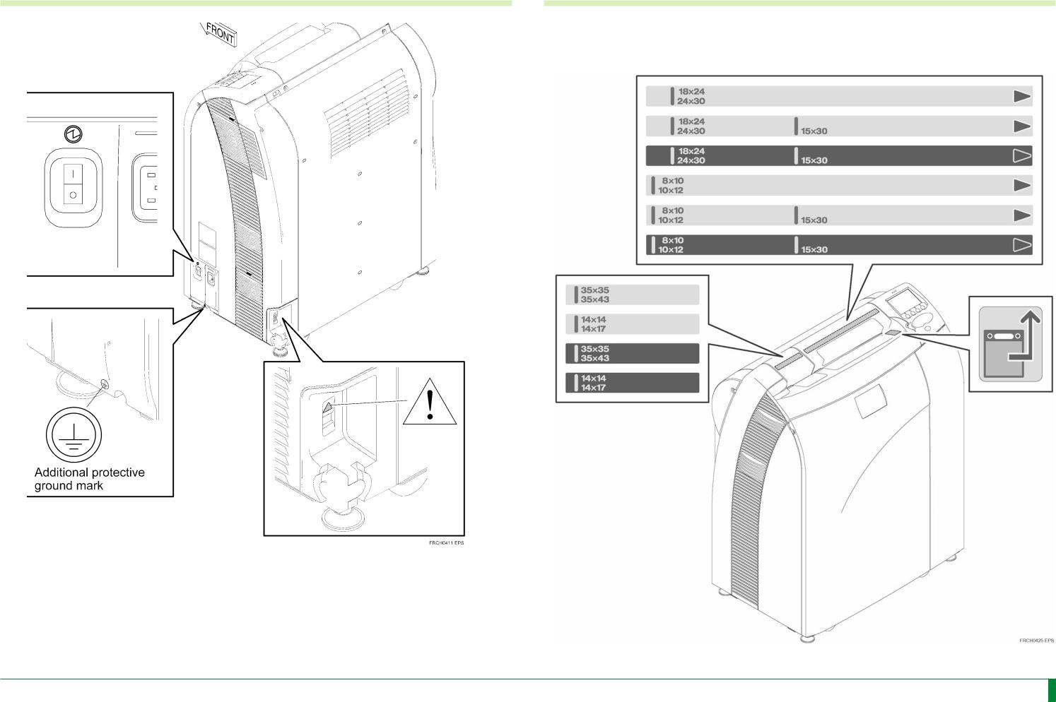
2.2 |
Ratings Indication Labels |
Ratings Indication Labels |
Attachment Position
014-204-01E 11.10.2005 FM4750
CR-IR 357 Service Manual |
Safety-6 |

Safety-7
2.3 |
Handling Instruction Labels and Attachment Locations |
2.3.3 |
Side-Positioning Conveyor Unit |
2.3.1Cassette Set Unit
2.3.2Erasure Unit
014-204-01E 11.10.2005 FM4750
CR-IR 357 Service Manual |
Safety-7 |
Safety-8
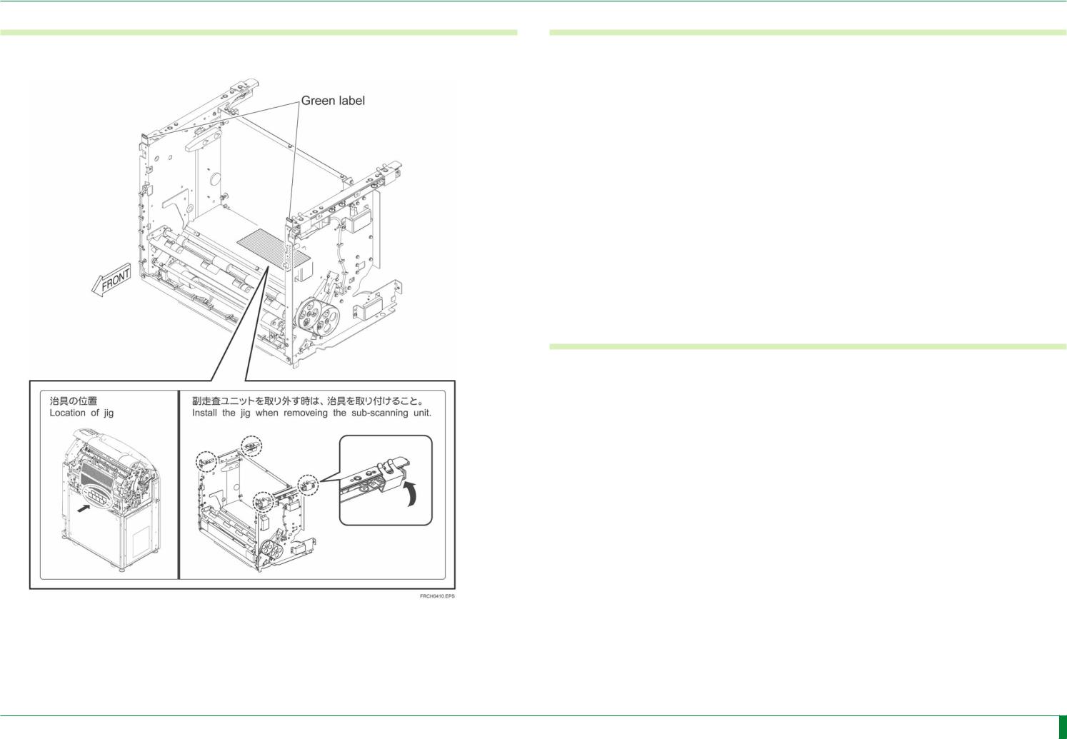
2.3.4 |
Subscanning Unit |
2.3.5 |
Light-Collecting Guide |
Hold the portions of the green labels to dismount/mount the subscanning unit from/on the housing.
2.3.6 Scanning Optics Unit
Hold the portions of the green labels to dismount/mount the scanning optics unit.
014-204-01E 11.10.2005 FM4750
CR-IR 357 Service Manual |
Safety-8 |
|
|
|
Safety-9 |
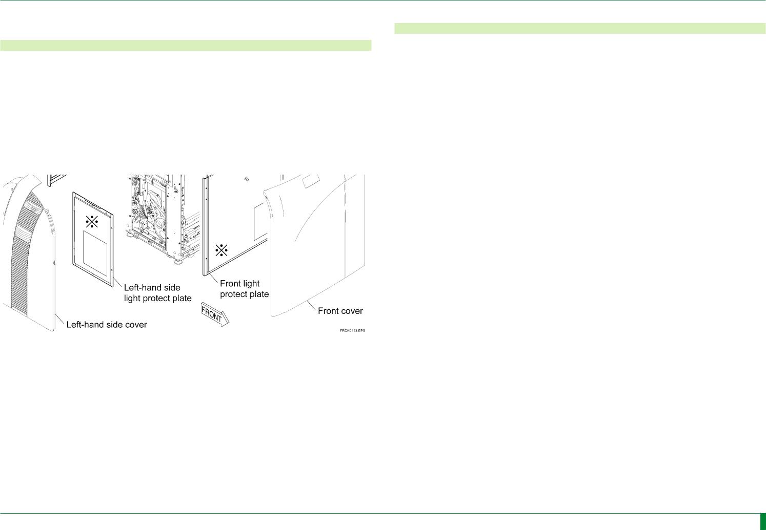
2.3.7 |
Covers |
2.3.8 |
Cassette Insertion Operation Label, Cassette Right-Justifying |
Label
The cassette insertion operation label differs depending on the type of the cassette used in the user’s site.
014-204-01E 11.10.2005 FM4750
CR-IR 357 Service Manual |
Safety-9 |

Safety-10
2.3.9 |
Lead Precaution Label |
2.3.10 |
Power Cable Caution Label |
Apply the lead precaution label suitable for the local language. |
Power Cable Caution Label (Only Hospital Grade Power Cable for U.S.A.) |
||
014-204-01E 11.10.2005 FM4750
CR-IR 357 Service Manual |
Safety-10 |
Safety-11
3.Protective Housings Against Laser Exposure
Even when the protective housings are removed for servicing, a laser beam will never leak out from the machine unless the optical path is intentionally changed. However, if the optical path is changed inadvertently during optics-related procedures, the service engineer or other people around the machine may be possibly exposed to laser radiation.
During optics-related procedures, carefully perform the procedures while checking the instructions described in this manual, and after the procedures are completed, restore the protective housings removed back exactly where they were.
Protective Housing of the Machine
The removable protective housings of the machine are illustrated below. The three covers marked by in the illustration below are protective housings against laser exposure.
4.CLASSIFICATION
1.According to the type of protection against electrical shock
CLASS 1 EQUIPMENT
2. According to the degree of protection against electrical shock
NO APPLIED PART
3. Protection against harmful ingress of water
IPXO
4. According to the degree of safety of application in the presence of a flammable anesthetics mixture with air or with oxygen or nitrous oxide.
Equipment not suitable for use in the presence of a flammable anesthetics mixture with air or with oxygen or nitrous oxide.
5. According to the mode of operation
CONTINUOUS OPERATION
014-204-01E 11.10.2005 FM4750
CR-IR 357 Service Manual |
Safety-11 |

Safety-12
5.Cautions on Electromagnetic Waves
5.1Electromagnetic Compatibility (EMC)
This equipment has been tested and found to comply with the limits for medical devices to the IEC60601-1-2 : 1993 (up to 24999), IEC60601-1-2 : 2001 (after 25001), Medical Device Directive 93/42/EEC.
These limits are designed to provide reasonable protection against harmful interference in a typical medical installation.
This equipment generates, uses and can radiate radio frequency energy and, if not installed and used in accordance with the instructions, may cause harmful interference to other devices in the vicinity.
However, there is no guarantee that interference will not occur in a particular installation.
If this equipment does cause harmful interference to other devices, which can be determined by tuning the equipment off and on, the user is encouraged to try to correct the interference by one or more of the following measures;
-Reorient or relocate the receiving device.
-Increase the separation between the equipment.
-Connect the equipment into an outlet on a circuit different from that to which the other device(s) are connected.
Consult the manufacturer or field service technician for help.
5.2Further information for IEC60601-1-2:2001
Model name CAPSULA X/CARBON X is referred to as CR-IR 357 in this section.
- Medical electrical equipment needs special precautions regarding EMC and needs to be installed and put into service according to the EMC information described as follows.
- Portable and mobile RF communications equipment can affect medical electrical equipment.
- The use of accessories, transducers and cables other than those specified, with the exception of transducers and cables sold by FUJI PHOTO FILM CO., LTD as replacement parts for internal components, may result in increased emissions or decreased immunity of the CR-IR 357.
List of Cables
Name |
Fuji Photo Film Parts code |
General Specification |
|
Power Cable |
136N0377 |
(Europe) |
- |
136N0376 |
(UK) |
||
I/F Cable |
- |
|
TIA/EIA-568 Cat5 or more. |
|
Straight cable of UTP type. |
||
|
|
|
|
- The CR-IR 363 should not be used adjacent to or stacked with other equipment.
If adjacent or stacked use is necessary, the CR-IR 357 should be observed to verify normal operation in the configuration in which it will be used.
Guidance and manufacturer’s declaration - electromagnetic emissions
The CR-IR 357 is intended for use in the electromagnetic environment specified below. The customer or the user of the CR-IR 357 should assure that it is used in such an environment.
Emissions test |
Compliance |
Electromagnetic environment - |
|
guidance |
|||
|
|
||
RF emissions |
|
The CR-IR 357 uses RF energy only |
|
CISPR 11 |
|
for its internal function. Therefore, its |
|
|
Group 1 |
RF emissions are very low and are not |
|
|
|
likely to cause any interference in nearby |
|
|
|
electronic equipment. |
|
RF emissions |
Class A |
|
|
CISPR 11 |
The CR-IR 357 is suitable for use in all |
||
|
|
||
|
|
establishments other than domestic and |
|
Harmonic emissions |
|
||
Class A |
those directly connected to the public |
||
IEC 61000-3-2 |
|||
low-voltage power supply network that |
|||
|
|
||
|
|
supplies buildings used for domestic |
|
Voltage fluctuations/ |
|
||
|
purposes. |
||
flicker emissions |
Complies |
||
|
|||
IEC 61000-3-3 |
|
|
014-204-01E 11.10.2005 FM4750
CR-IR 357 Service Manual |
Safety-12 |
Safety-13
Guidance and manufacturer’s declaration - electromagnetic immunity
The CR-IR 357 is intended for use in the electromagnetic environment specified below. The customer or the user of the CR-IR 357 should assure that it is used in such an environment.
Immunity test |
IEC 60601test level |
Compliance level |
Electromagnetic |
environment - |
|||
|
|
|
guidance |
Electrostatic |
±6kV contact |
±2kV contact |
Floors should be |
discharge (ESD) |
±8kV air |
±4kV contact |
wood, concrete or |
IEC 61000-4-2 |
±6kV contact |
ceramic tile. If floors |
|
|
±2kV air |
are covered with |
|
|
|
synthetic material, |
|
|
|
±4kV air |
the relative humidity |
|
|
±8kV air |
should be at least |
|
|
|
30%. |
Electrical fast |
±2kV for power supply |
±2kV for power supply |
Mains power quality |
transient/burst |
lines |
lines |
should be that of a |
IEC 61000-4-4 |
±1kV for input/output |
±1kV for input/output |
typical commercial or |
lines |
lines |
hospital environment. |
|
Surge |
±1kV differential mode |
±1kV differential mode |
Mains power quality |
IEC 61000-4-5 |
±2kV common mode |
±2kV common mode |
should be that of a |
typical commercial or |
|||
|
|
|
hospital environment. |
Voltage dips, short |
< 5 % UT |
< 5 % UT |
Mains power quality |
interruptions and |
(>95% dip in UT) |
(>95% dip in UT) |
should be that of a |
voltage variations on |
for 0.5 cycle |
for 0.5 cycle |
typical commercial or |
power supply input |
|
|
hospital environment. |
lines |
40 % UT |
40 % UT |
If the user of the |
IEC 61000-4-11 |
(60% dip in UT) |
(60% dip in UT) |
CR-IR 357 requires |
for 5 cycles |
for 5 cycles |
continued operation |
|
|
|
|
during power mains |
|
70 % UT |
70 % UT |
interruptions, it is |
|
(30% dip in UT) |
(30% dip in UT) |
recommended that |
|
for 25 cycles |
for 25 cycles |
the CR-IR 357 be |
|
|
|
powered from an |
|
< 5 % UT |
< 5 % UT |
uninterruptible power |
|
(>95% dip in UT) |
(>95% dip in UT) |
supply or a battery. |
|
for 5 s |
for 5 s |
|
|
|
|
|
Power frequency |
3 A/m |
3 A/m |
Power frequency |
(50/60 Hz) magnetic |
|
|
magnetic fields |
field |
|
|
should be at levels |
IEC 61000-4-8 |
|
|
characteristic of a |
|
|
typical location in a |
|
|
|
|
typical commercial or |
|
|
|
hospital environment. |
NOTE: UT is the a.c. mains voltage prior to application of the test level. |
|
||
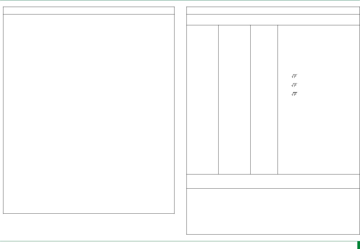
Guidance and manufacturer’s declaration - electromagnetic immunity
The CR-IR 357 is intended for use in the electromagnetic environment specified below. The customer or the user of the CR-IR 357 should assure that it is used in such an environment.
Immunity test |
IEC 60601 test |
Compliance |
Electromagnetic environment - guidance |
|
level |
level |
|
Conducted RF |
3 Vrms |
3 Vrms |
Portable and mobile RF communications |
IEC 61000-4-6 |
150kHz - |
|
equipment should be used no closer to any |
|
part of the CR-IR 357, including cables, |
||
|
80MHz |
|
than the recommended separation distance |
|
|
|
calculated from the equation applicable to |
|
|
|
the frequency of the transmitter. |
|
|
|
Recommended separation distance |
|
Radiated RF |
3 V/m |
3 V/m |
d = 1.2 |
|
IEC 61000-4-3 |
80MHz - |
|
d = 1.2 |
80 MHz - 800 MHz |
|
2.5GHz |
|
||
|
|
|
|
|
|
|
|
d = 2.3 |
800 MHz - 2.5 GHz |
|
|
|
where P is the maximum output power rating |
|
|
|
|
of the transmitter in watts (W) according to |
|
|
|
|
the transmitter manufacturer and d is the |
|
|
|
|
recommended separation distance in metres |
|
|
|
|
(m). |
|
|
|
|
Field strengths from fixed RF transmitters, |
|
|
|
|
as determined by an electromagnetic site |
|
|
|
|
survey,a |
should be less than the compliance |
|
|
|
level in each frequency range.b |
|
|
|
|
Interference may occur in the vicinity |
|
|
|
|
of equipment marked with the following |
|
|
|
|
symbol: |
|
NOTE 1 At 80 MHz and 800 MHz, the higher frequency range applies.
NOTE 2 These guidelines may not apply in all situations. Electromagnetic propagation is affected by absorption and reflection from structures, objects and people.
aField strength from fixed transmitters, such as base stations for radio (cellular/cordless) telephones and land mobile radios, amateur radio, AM and FM radio broadcast and TV broadcast cannot be predicted theoretically with accuracy. To assess the electromagnetic environment due to fixed RF transmitters, an electromagnetic site survey should be considered. If the measured field strength in the location in which the CR-IR 357 is used exceeds the applicable RF compliance, the CR-IR 357 should be observed to verify normal operation. If abnormal performance is observed, additional measures may be necessary, such as reorienting or relocating the CR-IR 357.
b Over the frequency range 150 kHz to 80 MHz, field strength should be less than 3 V/m.
014-204-01E 11.10.2005 FM4750
CR-IR 357 Service Manual |
Safety-13 |
Loading...