


 Loading...
FinePix F710
US/CA/EU/EG/GE/AS/JP-MODEL
SERVICE MANUAL

 WARNING
THE COMPONENTS IDENTIFIED BY THE MARK “  ” ON THE SCHEMATIC DIAGRAM AND IN THE PARTS LIST ARE CRITICAL FOR SAFETY.
PLEASE REPLACE ONLY BY THE COMPONENTS SPECIFIED ON THE SCHEMATIC DIAGRAM AND IN THE PARTS LIST.
IF YOU USE PARTS NOT SPECIFIED, IT MAY RESULT IN A FIRE AND AN ELECTORICAL SHOCK.
FUJI PHOTO FILM CO.,LTD.
Ref.No.:ZM00545-102
Printed in Japan 2004.04(H.I.)
Fine Pix F710 SERVICE MANUAL
SAFETY CHECK-OUT
2. Check the interboard wiring to ensure that no wires
are “pinched” or contact high-wattage resistors.
2.5A 125V
2.5A 125V
RISK OF FIREREPLACE FUSE AS MARKED
WARNING!
HIGH VOLTAGE
2

Fine Pix F710 SERVICE MANUAL
TABLE OF CONTENTS
1.General .................................................... |
4 |
1-1.Product specification ............................................... |
4 |
1-2.Explanation of Terms ............................................... |
7 |
1-3.Name of External Components ............................... |
8 |
2.Disassembly ............................................. |
9 |
2-1.Name of Internal Parts ............................................ |
9 |
2-2.How to Disassemble the REAR ASSY. ................ |
10 |
2-3.How to Disassemble the LENS CONST. ................ |
11 |
2-4.How to Disassemble the MAIN/DC BLOCK. ......... |
12 |
2-5.How to Disassemble the STROBE CONST. ......... |
12 |
2-6.How to Disassemble of MAIN/DC PWB. ............... |
13 |
2-7.How to Disassemble of REAR PWB ASSY. .......... |
14 |
2-8.How to Disassemble of CCD FPC ASSY. ............. |
15 |
2-9.Location of Sheet Parts. ........................................ |
16 |
2-9-1.SHEET (MAIN ) (FZ05860-100) ..................... |
16 |
2-9-2.MODE SHEET (BB17137-100) ...................... |
16 |
2-9-3.EMI SHEET(LCD)(FZ05861-100) .................. |
17 |
2-9-4.SHEET EMI (REAR)(FZ05889-100) ............... |
17 |
2-9-5.POLYIMIDE TAPE .......................................... |
17 |
2-9-6.SHEET EMI (ST) (FZ05867-100) ................... |
18 |
2-9-7.SHEET EMI R PANEL (FZ05868-100) ........... |
18 |
2-9-8.POLYIMIDE TAPE2 ........................................ |
18 |
2-10.Electronic part installation specification .............. |
19 |
2-10-1.ROTARY ENCODER SWITCH (FZ05596-100) . 19 |
|
4.Adjustment ............................................. |
42 |
4-1.Important point Adjustment when Replacing Major Parts |
42 |
4-2.Measuring Instruments Used ................................ |
42 |
4-3.Use Jig list ............................................................. |
42 |
4-4.Jig Connections .................................................... |
43 |
4-5.Environmental Setup ............................................. |
43 |
4-6.Installing the Jig Drivers on the PC ....................... |
45 |
4-7.Installing and Starting the Adjustment Software ... |
45 |
4-8. Initial Settings of the Adjustment Software .......... |
46 |
4-9. Starting the Adjustment Software ......................... |
49 |
4-10.[F4]:CCD Defect Data Input ................................ |
51 |
4-11.[F5]:CAM Adjustment .......................................... |
53 |
4-12. [F6] AF Adjustment ............................................. |
56 |
4-13.[F7]:Flash Adjustment ......................................... |
58 |
4-14.[F1]:Battery Adjustment ....................................... |
60 |
4-15.[F11]:Video Adjustment ....................................... |
63 |
4-16. [F3] LCD Adjustment ......................................... |
65 |
4-17. [F12] : End Setting ............................................. |
66 |
4-18.[F8]:Firmwaer Download ..................................... |
70 |
5.Inspectuon .............................................. |
72 |
5-1.Required Measuring Equipment .......................... |
72 |
5-2.Connection of Measuring Equipment ................... |
72 |
5-3.Inspection .............................................................. |
72 |
5-4.Factory setting ...................................................... |
73 |
3.Circuit Diagrams ..................................... |
21 |
6.Parts list ................................................. |
74 |
|
3-1.Cautions ................................................................ |
21 |
6-1.Packing and Accessoris ........................................ |
74 |
|
3-2.Names and Functions of Basic Blocks ................. |
21 |
6-1-1.US-model ....................................................... |
74 |
|
3-3.Explanation of Functions of Important Blocks. ...... |
21 |
6-1-2.CA-model ....................................................... |
75 |
|
3-3-1.Technical Overview ........................................ |
21 |
6-1-3.EU-model ....................................................... |
76 |
|
3-3-2.Explanation of Functions of Individual Blocks. 22 |
6-1-4.EG-model ....................................................... |
77 |
||
3-4.Block Diagram ....................................................... |
23 |
6-1-5.GE-model ....................................................... |
78 |
|
3-5.Overall ................................................................... |
24 |
6-1-6.AS-model ........................................................ |
79 |
|
3-6.Mounted Parts Diagrames .................................... |
25 |
6-1-7.JP-model ........................................................ |
80 |
|
3-6-1.MAIN PWB ASSY ........................................... |
25 |
6-2.Mechanical block .................................................. |
81 |
|
3-6-2.DC PWB ASSY ............................................... |
26 |
6-2-1.US/CA/EU/EG/GE/AS/JP-model .................... |
81 |
|
3-6-3.REAR PWB ASSY .......................................... |
27 |
6-3.Electrical parts ...................................................... |
82 |
|
3-6-4.MODE FPC ASSY .......................................... |
29 |
|
|
|
3-6-5.CCD FPC ASSY ............................................. |
29 |
7.Appendix |
84 |
|
3-7.Circuit Diagrames |
30 |
|||
7-1. Version display function |
84 |
|||
3-7-1.DCDC |
30 |
|||
7-2.List of Related Technical Updates Issued |
85 |
|||
3-7-2.PROCESS |
31 |
|||
|
|
|||
3-7-3.CAM ................................................................ |
32 |
|
|
|
3-7-4.LCD ................................................................ |
33 |
|
|
|
3-7-5.IPS .................................................................. |
34 |
|
|
|
3-7-6.MOTOR .......................................................... |
35 |
|
|
|
3-7-7.USB2 .............................................................. |
36 |
|
|
|
3-7-8.KEY ................................................................ |
37 |
|
|
|
3-7-9.AUDIO ............................................................ |
38 |
|
|
|
3-7-10.CHG .............................................................. |
38 |
|
|
|
3-7-11.CCD FPC ...................................................... |
39 |
|
|
|
3-7-12.MODE FPC ................................................... |
39 |
|
|
|
3-7-13.LED FPC ...................................................... |
39 |
|
|
|
3-7-14.VIDEO/JACK ................................................ |
40 |
|
|
|
3
1.General |
Fine Pix F710 SERVICE MANUAL |
|
|
1.General
1-1.Product specification
System
Model |
Digital camera FinePix F710 |
|
|
|
||
Effective pixels |
6.2 million (S-pixel: 3.1million, R-pixel: 3.1million) pixels |
|
||||
CCD |
1/1.7-inch Super CCD SR |
|
|
|
||
|
Number of total pixels: 6.7 million (S-pixel: 3.35 million, R-pixel: 3.35 million) pixels |
|||||
Storage media |
xD-Picture Card (16/32/64/128/256/512 MB) |
|
|
|||
File format |
Still image: DCF-compliant |
|
|
|
||
|
|
Compressed: Exif Ver.2.2 JPEG, DPOF-compatible |
|
|||
|
|
* Design rule for Camera File System compliant DPOF compatible |
||||
|
|
Uncompressed: CCD-RAW (RAF) |
|
|
||
|
Movie: AVI format, Motion JPEG |
|
|
|
||
|
Audio: WAVE format, Monaural sound |
|
|
|||
Number of recorded pixels |
Still image: (STD) 2832 × 2128 pixels/2048 |
pixels/1600 × 1200 pixels/ |
|
|||
|
|
1280 × 960 pixels |
|
) |
|
|
|
|
(WIDE) 2816 × 1584 pixels/2304 |
pixels/2048 × 1152 pixels/ |
|||
|
|
|
1536 × 864 pixels |
|
|
|
|
Movie: (STD) 640 × 480 pixels/320 × 240 pixels |
) |
|
|||
|
|
(30 frames per second with monaural |
|
|||
|
|
(WIDE) 640 × 360 pixels/320 × 184 pixels |
) |
|
||
|
|
(30 frames per second with monaural sound) |
|
|||
Lens |
Fujinon 4× zoom lens, F2.8-F5.6 |
|
|
|
||
Focal length |
f=7.2 mm-28.8 mm (STD: Equivalent to 32.5 mm-130 mm, |
|
||||
|
WIDE: Equivalent to 35.5 mm-142 mm on a 35 mm camera) |
|
||||
Focus |
TTL contrast-type, Auto focus, Manual focus |
|
|
|||
Focal range |
Normal: Approx. 60 cm (2.0ft.) to infinity |
|
|
|||
|
Macro: Approx. 7.5 cm (3.0 in.) to 80 cm (2.6 ft.) |
|
|
|||
Shutter speed |
3 sec. to 1/2000 sec. (depend on Exposure mode) |
|
|
|||
Aperture |
|
F8 10 steps in 1/3 EV increments Manual/Auto selectable |
|
|||
Sensitivity |
: Equivalent to ISO 160-800 |
|
|
|
||
|
Manual: Equivalent to ISO 200/400/800/1600 (resolution is set |
” for |
||||
|
|
shots taken at ISO 1600.) |
|
|
|
|
|
|
During setting CCD-RAW ISO 200/400 |
|
|
||
Photometry |
TTL 64-zones |
|
|
|
|
|
Exposure control |
Program |
, |
), Shutter-priority AE, Aperture-priority AE, |
|||
|
Manual exposure |
|
|
|
|
|
Exposure compensation |
-2 EV |
EV |
step increments (in Manual mode) |
|
||
White balance |
Auto |
|
) |
|
|
|
|
Manual modes, 8 positions can be selected (P, S, A, M) |
|
||||
Viewfinder |
Real image optical |
Approx. 77% coverage |
|
|
||
LCD monitor |
2.1-inches, Aspect ratio: 16:9; 173,000 pixels widescreen CG sillicon TFT, |
|||||
|
Approx. 100% coverage |
|
|
|
||
Flash Type |
Auto flash using flash control sensor |
|
|
|
||
|
Effective range: Wide-angle: Approx. 0.3 m-5.5 m (1.0 ft.-18.0 ft.) |
|
||||
|
|
(Approx. 0.3 m-0.8 m (1.0 ft.-2.6 ft.): Macro) |
|
|||
|
Telephoto: Approx. 0.6 m-4.0 m (2.0 ft.-13.1 ft.) |
|
|
|||
|
Flash modes: Auto, Red-Eye Reduction, Forced Flash, Suppressed Flash, Slow |
|||||
|
|
Synchro, Red-Eye Reduction + Slow Synchro |
|
|||
Self-Timer |
2 sec./10 sec. |
|
|
|
|
|
Input/Output Terminals
External connection terminals |
|
Special USB cable, special A/V cable, cradle connection |
DC Input |
|
To connect the AC power Adapter AC-5VW |
|
4

Fine Pix F710 SERVICE MANUAL |
|
|
1.General |
||||
|
|
|
|
|
|
|
|
|
|
|
|
|
|
|
|
Power Supply and Others |
|
|
|
|
|
||
Power supply |
Use one of the following |
|
|
|
|||
|
• Rechargeable Battery NP-40 or AC Power Adapter AC-5VW |
||||||
Conditions for use |
Temperature: 0oC to +40oC (+32oF to +104oF) |
|
|
|
|||
|
80% humidity or less (no condensation) |
|
|
|
|||
Guide to the number |
|
|
|
|
|
|
|
Battery |
|
LCD monitor status |
|
Number of frames |
|
|
|
of available frames |
|
|
LCD monitor ON |
|
Approx. 135 |
|
|
for battery operation |
NP-40 |
|
|
|
|||
|
|
|
|
|
|
||
|
LCD monitor OFF |
|
Approx. 270 |
|
|
||
|
|
|
|
|
|||
|
|
|
|
|
|
|
|
The number of available frames for battery operation given here is a guide to the number of consecutive shots that can be taken under FUJIFILM test conditions.
•Battery used: NP-40 Rechargeable Battery bundled with the camera (fully charged)
•Shooting conditions: Measured at normal temperature with 50% flash use
•Note: Because the number of available frames that can be taken varies depending on the amount of charge in NP-40, the figures given here for the number of frames that can be taken using battery is not guaranteed. At low tempera-
|
tures, fewer pictures can be taken when the camera is running on battery. |
|||
Camera dimensions |
109.5 mm × 54 mm × 28.9 mm/4.3 in. × 2.1 in. × 1.1 in. |
|||
(W × H × D) |
(not including accessories and attachments) |
|
||
Camera mass (weight) |
210 g/7.4 oz. (not including accessories, battery, xD-Picture Card) |
|||
Weight for photography |
Approx. 225 g/7.9 oz. (including battery NP-40 and xD-Picture Card) |
|||
Accessories |
NP-40 Rechargeable Battery (1) |
Soft case included |
||
|
16 MB, xD-Picture Card (1) included with: Anti-static case (1) |
|||
|
Strap (1) |
AC Power Adapter AC-5VW (1 set) |
||
|
A/V cable for the FinePix F710 (1) |
(approx. 1.2 m (3.9 ft.)) |
||
|
USB cable (1) (approx. 1.2 m (3.9 ft.)) |
|
||
|
Picture Cradle (1) |
CD-ROM (1) |
Software for FinePix AX |
|
|
Owner’s Manual (1) |
|
|
|
Optional Accessories |
xD-Picture Card |
|
|
|
|
DPC-16 (16 MB)/DPC-32 (32 MB)/DPC-64 (64 MB)/DPC-128 (128 MB)/ |
|||
|
DPC-256 (256 MB)/DPC-512 (512 MB) |
|
||
|
Battery Charger BC-65 |
Rechargeable Battery NP-40 |
||
|
AC Power Adapter AC-5VH/AC-5VHS |
Soft Case SC-FX701 |
||
Image Memory Card Reader DPC-R1
•Compatible with Windows 98/98 SE, Windows Me, Windows 2000 Professional, Windows XP or iMac, Mac OS 8.6 to 9.2, Mac OS X (10.1.2 to 10.2.2) and models that support USB as standard.
•Compatible with xD-Picture Card of 16 MB to 512 MB, and SmartMedia of
3.3V, 4 MB to 128 MB.
PC Card Adapter DPC-AD
•Compatible with xD-Picture Card of 16 MB to 512 MB, and SmartMedia of
3.3V, 2 MB to 128 MB.
CompactFlash Card Adapter DPC-CF
•Windows 95/98/98 SE/Me/2000 Professional/XP
•Mac OS 8.6 to 9.2/X (10.1.2 to 10.1.5)
xD-Picture Card USB Drive DPC-UD1
•Compatible with xD-Picture Card of 16 MB to 512 MB
•Windows 98/98 SE/Me/2000 Professional/XP
•Mac OS 9.0 to 9.2/X (10.0.4 to 10.2.6)
Cradle
Cradle dimensions |
126.5 mm × 48.3 mm × 69.2 mm/5.0 in. × 1.9 in. × 2.7 in. |
(W × H × D) |
|
Cradle mass (weight) |
Approx. 80 g/2.8 oz. |
5

1.General |
Fine Pix F710 SERVICE MANUAL |
|
|
 Standard number of frames per xD-Picture Card (STD)
Quality setting |
F |
N |
|
|
|
|
Number of recorded pixels |
2832 2128 |
2832 2128 |
2048 1536 |
1600 1200 |
1280 960 |
2832 2128 |
|
|
|
|
|
|
|
Image Data Size |
3.0 MB |
1.5 MB |
780 KB |
620 KB |
460 KB |
12.9 MB |
|
|
|
|
|
|
|
DPC-16 (16 MB) |
5 |
10 |
19 |
25 |
33 |
1 |
|
|
|
|
|
|
|
DPC-32 (32 MB) |
10 |
21 |
40 |
50 |
68 |
2 |
|
|
|
|
|
|
|
DPC-64 (64 MB) |
21 |
42 |
81 |
101 |
137 |
4 |
|
|
|
|
|
|
|
DPC-128 (128 MB) |
42 |
85 |
162 |
204 |
275 |
9 |
|
|
|
|
|
|
|
DPC-256 (256 MB) |
86 |
171 |
325 |
409 |
550 |
19 |
|
|
|
|
|
|
|
DPC-512 (512 MB) |
172 |
343 |
651 |
818 |
1101 |
39 |
|
|
|
|
|
|
|
 Standard number of frames per xD-Picture Card (WIDE)
Quality setting |
F |
N |
|
|
|
Number of recorded pixels |
2816 1584 |
2816 1584 |
2304 1296 |
2048 1152 |
1536 864 |
|
|
|
|
|
|
Image Data Size |
2.2 MB |
1.1 MB |
740 KB |
700 KB |
500 KB |
|
|
|
|
|
|
DPC-16 (16 MB) |
6 |
14 |
20 |
22 |
30 |
|
|
|
|
|
|
DPC-32 (32 MB) |
14 |
28 |
41 |
44 |
61 |
|
|
|
|
|
|
DPC-64 (64 MB) |
28 |
57 |
84 |
90 |
124 |
|
|
|
|
|
|
DPC-128 (128 MB) |
58 |
115 |
169 |
181 |
249 |
|
|
|
|
|
|
DPC-256 (256 MB) |
116 |
231 |
339 |
362 |
499 |
|
|
|
|
|
|
DPC-512 (512 MB) |
232 |
462 |
679 |
725 |
998 |
|
|
|
|
|
|
 Standard recording Times for xD-Picture Card (STD)
Quality setting |
(30 fps) |
(30 fps) |
Number of recorded pixels |
640 480 |
320 240 |
|
|
|
DPC-16 (16 MB) |
13 sec. |
26 sec. |
|
|
|
DPC-32 (32 MB) |
27 sec. |
54 sec. |
|
|
|
DPC-64 (64 MB) |
55 sec. |
109 sec. |
|
|
|
DPC-128 (128 MB) |
111 sec. |
219 sec. |
|
|
|
DPC-256 (256 MB) |
223 sec. |
7.3 min. |
|
|
|
DPC-512 (512 MB) |
7.4 min. |
14.6 min. |
|
|
|
 Standard recording Times for xD-Picture Card (WIDE)
Quality setting |
(30 fps) |
(30 fps) |
Number of recorded pixels |
640 360 |
320 184 |
|
|
|
DPC-16 (16 MB) |
18 sec. |
34 sec. |
|
|
|
DPC-32 (32 MB) |
36 sec. |
70 sec. |
|
|
|
DPC-64 (64 MB) |
73 sec. |
141 sec. |
|
|
|
DPC-128 (128 MB) |
147 sec. |
283 sec. |
|
|
|
DPC-256 (256 MB) |
296 sec. |
9.4 min. |
|
|
|
DPC-512 (512 MB) |
9.8 min. |
18.9 min. |
|
|
|
The number of available frames, recording time or file size varies slightly depending on the subjects photographed. Note also that the between standard number of available frames and the actual number of frames is greater for xD-Picture Card with higher capacities.
6

Fine Pix F710 SERVICE MANUAL |
1.General |
|
|
|
|
1-2.Explanation of Terms |
|
|
AF/AE Lock: |
On the FinePix F710, pressing the Shutter button down half way locks the focus |
|
|
and exposure settings (AF and AE lock). If you want to focus on a subject that is |
|
not centered in the frame or change the picture composition after the exposure is set, you can obtain good results by changing the composition after the AF and AE settings are locked.
Auto power save function: If the camera is not used in any way for 30 seconds, this function turns features such as the LCD monitor off (Sleep mode) to prevent battery depletion and the waste of power when the AC power adapter is connected. If the camera is then left unused for a further period, the Auto power save function turns the camera off. This period can be set to 2 minutes or 5 minutes on this camera.
The Auto power off function does not operate in PC mode, during automatic playback, or if it is disabled during setup.
DPOF: |
Digital Print Order Format |
|
DPOF is a format used for recording information on a storage media (image |
|
memory card, etc.) that allows you to specify which of the frames shot using a |
|
digital camera are to be printed and how many prints are made of each image. |
EV: |
A number that denotes Exposure Value. The EV is determined by the brightness |
|
of the subject and sensitivity (speed) of the film or CCD. The number is larger for |
|
bright subjects and smaller for dark subjects. As the brightness of the subject |
|
changes, a digital camera maintains the amount of light hitting the CCD at a con- |
|
stant level by adjusting the aperture and shutter speed. |
|
When the amount of light striking the CCD doubles, the EV increases by 1. Like- |
|
wise, when the light is halved, the EV decreases by 1. |
Frame rate (fps): |
The frame rate refers to the number of images (frames) that are photographed or |
|
played back per second. For example, when 10 frames are continuously photo- |
|
graphed in a 1-second interval, the frame rate is expressed as 10 fps. |
|
For reference, TV images are displayed at 30 fps. |
JPEG : |
Joint Photographics Experts Group |
|
A file format used for compressing and saving color images. The higher the com- |
|
pression rate, the greater the loss of quality in the decompressed (restored) image. |
Motion JPEG: |
A type of AVI (Audio Video Interleave) file format that handles images and sound |
|
as a single file. Images in the file are recorded in JPEG format. Motion JPEG can |
|
be played back by QuickTime 3.0 or later. |
PC Card: |
A generic term for cards that meet the PC Card Standard. |
PC Card Standard: |
A standard for PC cards determined by the PCMCIA. |
PCMCIA: |
Personal Computer Memory Card International Association (US). |
Smear: |
A phenomenon specific to CCDs whereby white streaks appear on the image |
|
when there is a very strong light source, such as the sun or reflected sunlight, in |
|
the photography screen. |
WAVE: |
A standard format used on Windows systems for saving audio data. WAVE files |
|
have the “.WAV” file extension and the data can be saved in either compressed or |
|
uncompressed format. Uncompressed recording is used on this camera. |
|
WAVE files can be played back on a personal computer using the following software: |
|
Windows: MediaPlayer |
|
Macintosh: QuickTime Player |
|
* QuickTime 3.0 or later |
White Balance: |
Whatever the kind of the light, the human eye adapts to it so that a white object |
|
still looks white. On the other hand, devices such as digital cameras see a white |
|
subject as white by first adjusting the color balance to suit the color of the ambient |
|
light around the subject. This adjustment is called matching the white balance. |
Exif Print: |
Exif Print Format is a newly revised digital camera file format that contains a vari- |
|
ety of shooting information for optimal printing. |
7
1.General |
Fine Pix F710 SERVICE MANUAL |
|
|
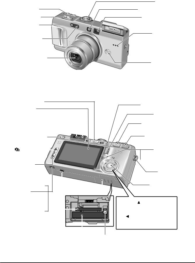
1-3.Name of External Components
Power switch |
Shutter button |
Flash control sensor
Self-timer lamp
Lens (Lens cover)
Mode dial
AF-Assist Illuminator
Viewfinder window
 Flash
Flash
Microphone
 Speaker
 DC IN 5V (power input) socket
C-AF button
WIDE/STD switch |
LCD monitor |
Viewfinder lamp |
Viewfinder |
Flash pop-up button |
Continuous |
shooting button |
 Exposure compensation button
 (USB) socket
A/V OUT (Audio / Visual
output) socket
 Cradle connection socket
Tripod mount |
Battery cover |
xD-Picture Card slot 
Battery compartment
Battery release catch 
Photo mode( ) button
Command dial
W (Wide zoom) button
T (Tele zoom) button
DISP (Display) button

 BACK button
Strap mount
MENU/OK button
4-direction ( 
 ) button
 (
( ) Photometry button
  ( ) Macro button
 (
( ) Flash button
8
Fine Pix F710 SERVICE MANUAL |
2.Disassembly |
|
|
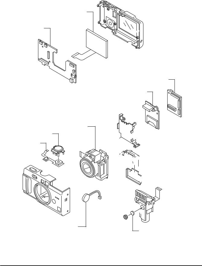
2.Disassembly
2-1.Name of Internal Parts
LCD CONST
REAR PWB ASSY
LENS CONST
M DIAL ASSY MODE FPC ASSY
FRONT ASSY
SPEAKER

 REAR ASSY
MAIN PWB ASSY
DC PWB ASSY
 MAIN FRAME ASSY
 CABI BASE ASSY


 BATTERY LID ASSY


 STROBE CONST
MICROPHONE
9
2.Disassembly |
Fine Pix F710 SERVICE MANUAL |
|
|
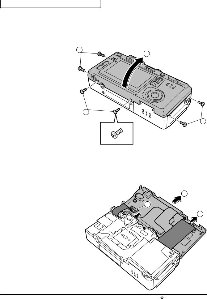
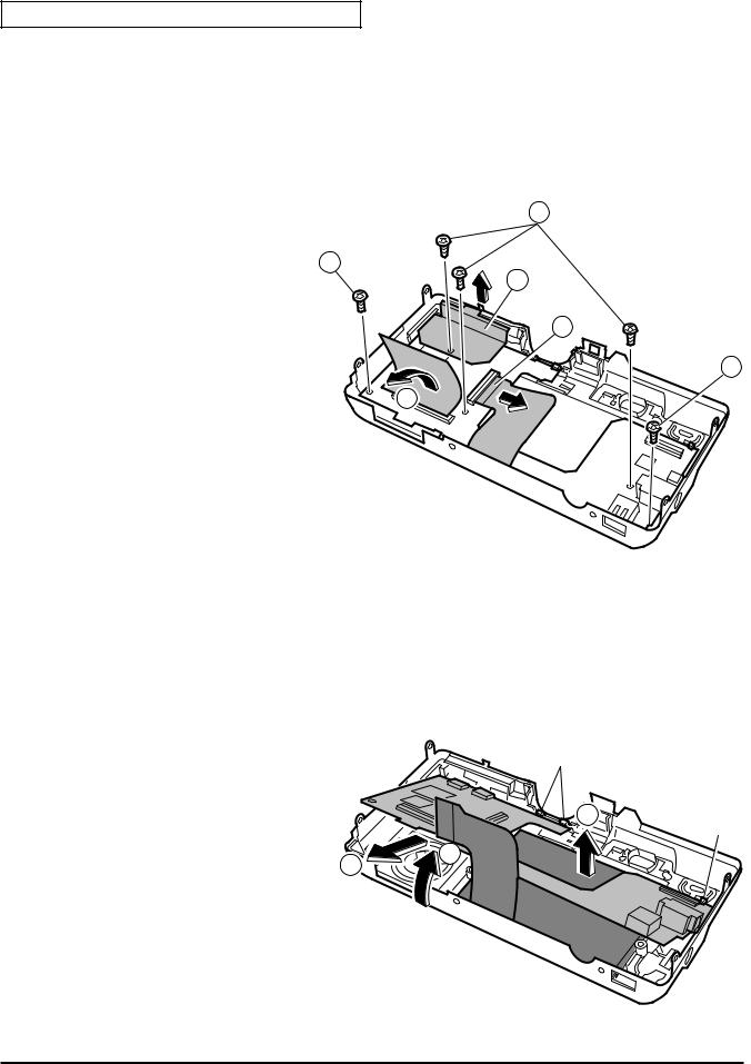
 2-2.How to Disassemble the REAR ASSY.
(1)Remove the 6 special shape screws.(3ULR 1.7X3.5)
*Because the screws are special shape,use the exclusive use jig driver(ZJ00538-100) (2)Remove the R ASSY in the direction of the arrow.
1
2
1
1
(3)Remove the FPC(STOROBE CONST) in the direction of the arrow. (REAR PWB CN601)
(4)Remove the FPC(MAIN PWB) in the direction of the arrow. (REAR PWB CN801)
(5)Remove the R ASSY in the direction of the arrow.
5
3
4
10 |
Revice April 28, 2004 |
Fine Pix F710 SERVICE MANUAL |
2.Disassembly |
|
|
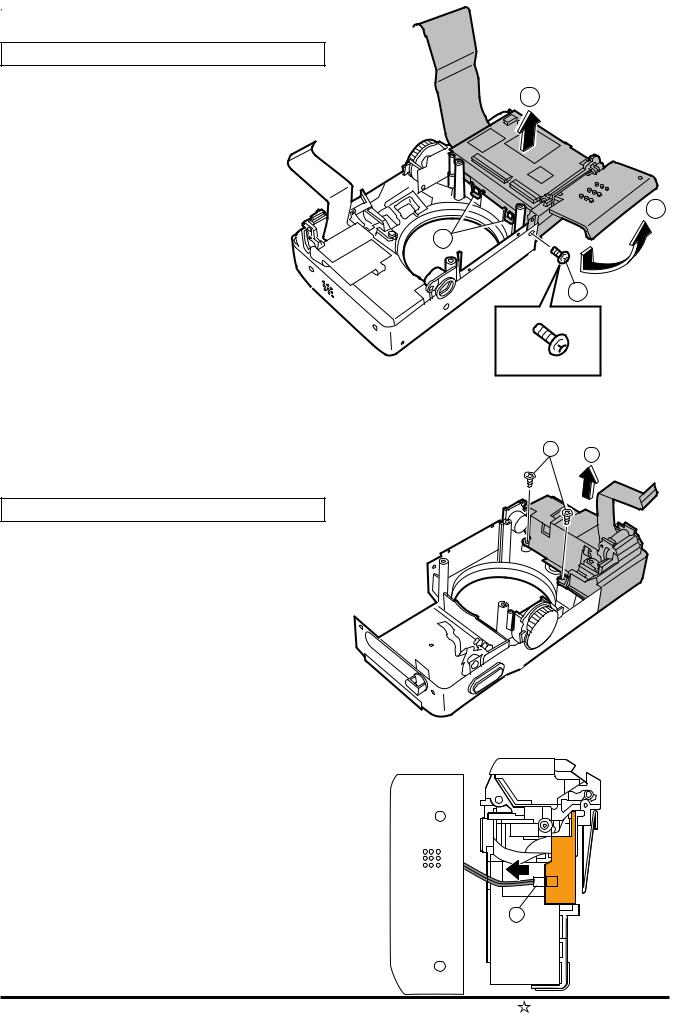
2-3.How to Disassemble the LENS CONST.
4
3
(1)Remove the SHEET MAIN in the direction of the arrow.
(2)Remove the FPC(MODE FPC) in the direction of the arrow. |
|
(3)Remove the 2 screws. |
|
(4)Remove the 1 screws. |
2 |
(5)Lift the LENS CONST in the direction of the arrow.
(6)Remove the FPC(LENS UNIT) in the direction of the arrow. |
1 |
|
|
(MAIN PWB CN151) |
|
(7)Remove the FPC(CCD FPC) in the direction of the arrow. |
|
(MAIN PWB CN101) |
|
8
(8)Remove the LENS CONST in the direction of the arrow.
5
6
7
C
B
A
No screw
[Attention when Reassemble]
Please stop a screw in (A)(B)(C) order.
11
2.Disassembly |
Fine Pix F710 SERVICE MANUAL |
|
|
2-4.How to Disassemble the MAIN/DC BLOCK.
(1)Remove the 6 special shape screws.(3ULR 1.7X3.5)
*Because the screws are special shape,use the exclusive use jig driver(ZJ00538-100)
4
(2)Open the Battery Cover in the direction of the arrow.
2
(3)Remove the hook of MAIN FRAME(2 place). |
3 |
|
|
(4)Remove the MAIN/DC BLOCK in the direction |
|
of the arrow. |
1 |
|
1 2
 2-5.How to Disassemble the STROBE CONST.
(1)Remove the 2 screws.
(2)Remove the STROBE CONST in the direction of the arrow.
(3)Remove the WIER HERNES(SPEAKER) in the direction the arrow. (STROBE CONST)
3
12 |
Revice April 28, 2004 |
Fine Pix F710 SERVICE MANUAL |
2.Disassembly |
|
|
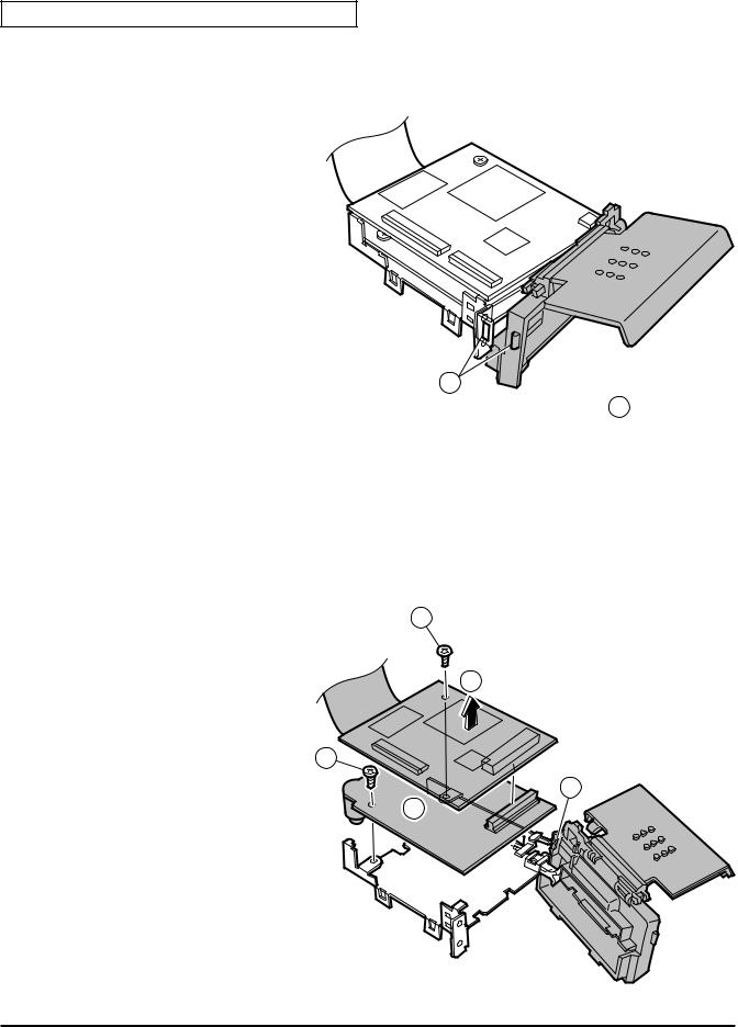
2-6.How to Disassemble of MAIN/DC PWB.
(1)Remove the hook of MAIN FRAME(1 place).
(2)Move the Battery Cover Block in the direction of the arrow.
1
 2
2
(3)Remove the 1 screw.
(4)Remove the MAIN PWB ASSY in the direction of the arrow.
(5)Remove the 1 screw.
(6)Remove the DC PWB ASSY in the direction of the arrow.
(7)Remove Battery Cover Block from the hook of MAIN FRAME.
3
4
5
7
6
13
2.Disassembly |
Fine Pix F710 SERVICE MANUAL |
|
|
2-7.How to Disassemble of REAR PWB ASSY.
(1)Remove the EMI SHEET R PANEL in the direction of the arrow.
(2)Remove the 3 screws.
(3)Remove the 2 screws.
(4)Remove the SHEET FPC in the direction of the arrow.
2
(5)Remove the LCDFPC in the direction of the arrow.
(REAR PWB CN802)
3
4
5
3
1
(6)Move the REAR PWB in the direction of the arrow.
(7)Remove the REAR PWB in the direction of the arrow.
(8)Remove the LCD UNIT in the direction of the arrow.
Fook
8
Fook
6
7
[Attention when Reassemble]
Confirm whether REA PWB hangs in the hook of REAR ASSY.(3 place)
14
Fine Pix F710 SERVICE MANUAL |
2.Disassembly |
|
|
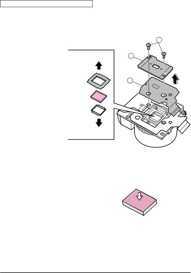
2-8.How to Disassemble of CCD FPC ASSY.
(1)Remove the 2 screws.
(2)Remove the CCD PLATE.
(3)Remove the CCD FPC ASSY n the direction of the arrow.
1
CCD 2
LPF |
3 |
|
RUBBER |
||
|
OPTICAL
LPF
LPF
MASK
LENS UNIT
[Attention when Reassemble.]
Set it in the mount of the lens in order of the LPF MASK,
OPTICAL LPF, and LPF RUBBER.
When reassembling parts, be careful dust is not adhering to the CCD, optical LPF or lens.
Install the OPTICAL LPF so that the IR cut-coated sur- |
|
face is on the CCD side. |
|
|
If the reddish reflection is to the front when light is |
Install the LPF RUBBER so that the Convex surface |
reflecting off the surface of the optical low-pass filter, |
is on the LENS side. |
this front end is the IR cut-coated surface. |
Set CCD FPC ASSY in the lens, draw to the under |
|
part of the left, and tighten the machine screw. |
|
15
2.Disassembly |
Fine Pix F710 SERVICE MANUAL |
|
|
2-9.Location of Sheet Parts.
[Attention when Reassemble.]
Do not use removed “Sheet Parts”.
Use surely new parts at the time of reassembly.
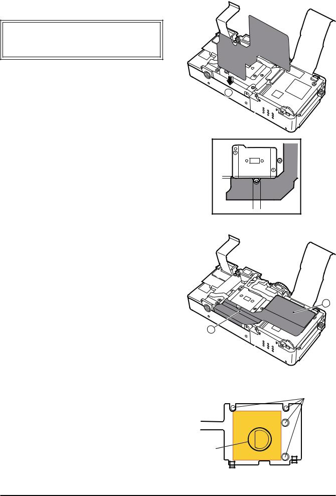
2-9-1.SHEET (MAIN ) (FZ05860-100)
(1)Insert SHEET(MAIN) between F ASSY and LENS UNIT.
(2)Insert the edge of SHEET(MAIN) under CCD PLATE.
*(A)Horizontal direction
Match the edge where the incision and LENS UNIT of SHEET(MAIN) are round.
*(B)Vertical direction (amount of insertion) Position that lightly does slide and stops.
(3)Put bonding seat part(C)(D) of SHEET(MAIN).
1
$ |
# |
C
D
2-9-2.MODE SHEET (BB17137-100) |
|
|
|
|
|
# |
||
Put MODE SHEET to close hole (B) of MODE FPC |
|
|
|
|
|
|
|
|
|
|
|
|
|
|
|
|
|
bottom.(MODE DIAL side) |
|
|
|
|
|
|
|
|
*Do not get on on the pin (four places). |
$ |
|
|
|
|
|
|
|
|
|
|
|
|
|
|
|
|
|
|
|
|
|
|
|
|
|
|
|
|
|
|
|
|
|
|
|
|
|
|
|
|
|
|
|
16

Fine Pix F710 SERVICE MANUAL |
2.Disassembly |
|
|
2-9-3.EMI SHEET(LCD)(FZ05861-100)
(1)Put EMI SHEET(LCD) on the terminal side side of FPC(LCD CONST).
*The putting starting position is an edge of FPC(A)(B).
(2)Turn EMI SHEET(LCD), and put on the back side of FPC(LCD CONST).
*The putting standard is an edge of FPC (C).
*Putting error margin "(A)(B)(C)"; Within 1mm from edge of FPC.
2-9-4.SHEET EMI (REAR)(FZ05889-100)
Put SHEET EMI (REAR) on the mode switch side of REAR PWB.
*The putting position of the vertical direction is (A) between "Bottom of SW601/654" and "Base part of CN801".
*Put it so as not to hang in SW601/654.
*A horizontal putting position is within 1mm from the edge of "Inner cabinet of R ASSY".
2-9-5.POLYIMIDE TAPE
M-R FPC ASSY is attached in MAIN PWB ASSY, and the polyimide tape is stuck on it.
*ZS00024-100(polyimide tape PIT652S) is cut in 19X25mm and it uses it.
*It puts it with M-R FPC ASSY bent from white line edge
(B).
*It matches it to side (A) of IC207 of MAIN PWB ASSY.
*Width (C) of the polyimide tape must not exceed it to the width of M_R FPC ASSY.
B
A C
B
MODE SHEET
A |
EMI SHEET |
|
|
|
CN801 |
C
 M_R FPC ASSY
 Polyimide Tape

 B
B 

CN201
 A
A 

 Revice April 28, 2004 17

2.Disassembly |
Fine Pix F710 SERVICE MANUAL |
|
|
2-9-6.SHEET EMI (ST) (FZ05867-100)
Put SHEET EMI(ST) under STROBE CONST.
*Put according to edge (A)(B) of the frame, and turn on the bottom side.
*SHEET EMI(ST) is included in STROBE CONST.
A
B
2-9-7.SHEET EMI R PANEL (FZ05868-100)
Put SHEET EMI R PANEL downward of LCD
CUSHION (inside of R ASSY).
*It is based on edge (A) of a metallic frame and cutting
lack edge (B).
A
*Error margin (C) is within 1mm. |
B |
*It doesn't run aground on the wall in INNER CABI.
*It doesn't slip between INNER CABI and PANEL.
C
*SHEET EMI R PANEL is included in R ASSY.
 2-9-8.POLYIMIDE TAPE2
A
LCD FPC is attached in REAR PWB ASSY, and the polyimide tape2 is stuck on it.
*ZS00024-100(polyimide tape PIT652S) is cut in 19X9mm and it uses it.
*It puts it based on edge (A) of the scaleboard of LCDFPC and center (B) of CN802.
*Confirm the terminal of CN802 has been covered.
 B 19mm

 LCD FPC 9mm
18 |
Revice April 28, 2004 |
Fine Pix F710 SERVICE MANUAL |
2.Disassembly |
|
|
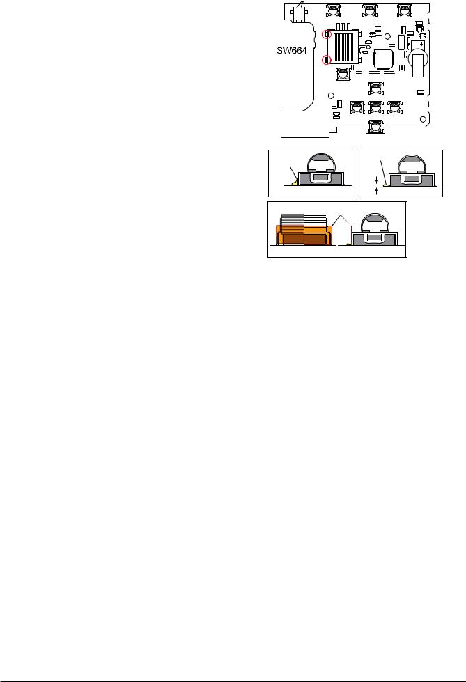
2-10.Electronic part installation specification
2-10-1.ROTARY ENCODER SWITCH (FZ05596-100)
Adjust the height of the solder part of ROTARY ENCODER SWITCH (2-place on the LCD side) to 1mm or less (A).
*Solder rises to the side of ROTARY ENCODER SWITCH in usual work (NG).
*The polyimide tape(B) is put on the ROTARY ENCODER SWITCH side to prevent it and the solder works. (removed after soldering)
*Cut and use Z00024-100 (polyimide tape PIT652S).
NG |
OK |
|
|
|
A |
B |
19

2.Disassembly |
Fine Pix F710 SERVICE MANUAL |
|
|
MEMO
20
Fine Pix F710 SERVICE MANUAL |
3.Schematics |
|
|
3.Circuit Diagrams
3-1.Cautions
Precautions in parts replacement
Do not reuse detached electronic components. Use only new components.
The negative side of tantalum capacitors is weak against heat. Handle with care.
With the exception of Chemical capacitor and tantalum capacitors, the voltage of capacitors of a 50V or lower withstand voltage is not labeled.
Unless specified, electronic component resistance is 1/16W.
K = 1000 , M = 1000 K
3-2.Names and Functions of Basic Blocks
Board Name |
Block Name |
Function |
|
|
|
|
|
CCD FPC |
CCD BLOCK |
CCD ouput(IC1) |
|
MAIN PWB |
CAM BLOCK |
Analog to Digital conversion of CCD Output(IC103) |
|
|
|
CCD V_Drv(IC102) OFD/RG/BIAS(IC101) |
|
|
PROCESS BLOCK |
Signal processing/System/Analog to Digital conversion of Audi/LCD backlight control(IC206) |
|
|
|
USB(IC301) Flash-Rom(IC207) |
SD-RAM(IC205) |
|
MOTOR BLOCK |
AF/Zoom/Iris/Shutter drive(IC151) |
|
DC PWB |
DCDC BLOCK |
Each power generation(IC401) Battery charge control (IC502) |
|
REAR PWB |
AUDIO BLOCK |
Audio signal processing (IC701) |
|
|
VIDEO BLOCK |
Video signal processing NTSC/PAL (IC751) |
|
|
IPS BLOCK |
Flash processing (IC601) |
|
|
KEY BLOCK |
Operation SW(CAM<->PB / TELE<->WIDE / R / L / U / D / OK / BACK / EXP / DRIVE |
|
|
|
WIDE / NOMAL / SEL_A / SEL_B) |
|
|
LCD BLOCK |
LCDsignal processing (IC802/IC804) |
|
|
|
|
|
LCD const |
LED back light |
|
|
MODE FPC |
|
Operation SW(S1/S2 MODE) |
|
|
|
|
|
STROBE CONST |
STOROBE BLOCK |
Flash charge and luminescence |
Operation SW(C_AF) |
|
|
|
|
3-3.Explanation of Functions of Important Blocks.
3-3-1.Technical Overview
1/1.7 inch Fourth Generation Super CCD SR sencer .
Total pixels: |
6.7 million |
(Main pixels:3.35 million / Sub pixels:3.35 million) |
|
Effective pixels: |
6.2 million |
(Main pixels:3.1 million / Sub pixels:3.1 million) |
|
Number of maximum record pixels: |
6.03 million (2832 X 2128 pixels) |
||
The optical system empolys a newly designed "Built-in lens barrier", "multistep iris", and 2-stage retracting barrel 4x zoom lens.(6 elements in 5 groups)
2.12 type 173,000 pixel minute reflection type CG silicon TFT color liquid crystal monitor is employed. (Aspect ratio 4:3 and 16:9)
The AF assistance light is installed. (Attainment distance about 2.5m (wide side))
New IC adopts "'IPS(IC601)' that builds in the flash control and power on the control, etc.", "Battery charge control IC(IC502)", "LCD control IC(IC802)", and "Lens system motor control IC(IC151)".
21

3.Schematics |
Fine Pix F710 SERVICE MANUAL |
|
|
3-3-2.Explanation of Functions of Individual Blocks.
(1)CCD signal Processing/Picture-taking Blocks (CCD BLOCK and CAM BLOCK)
The analog signals output by the CCD(1/1.7 inch Fourth Generation Super CCD SR sencer with 6.2 million effctive pixels[total](IC1)) undergo color compensation, adaptive interpolation, amplification (ACG) and signal mixing in the [ACS (IC103)] CCD signal processing IC. After that, the signals are converted into 12-bit digital signals and sent to the [UCS2 (IC206)] system LSI.
 This block has a [V-dr(IC101)] for driving the CCD. (2)Motor Block(MOTOR BLOCK)
Upon receiving commands from operating switches, the [UCS2 (IC206)] signal processing LSI manages the motor drive IC (IC151) so as to control the motors for AF, shutter, zoom and iris.
(3)Image Signal Processing Block(PROCESS BLOCK)
Input Data from the CCD
The 12-bit digital image data (equivalent to 1H) output by the image unit (CCD/CAM BLOCK) is sent to the [UCS2 (IC206)] system LSI. It is here converted into 32-bit data by the internal buffer of the LSI, and image data of 2832 x 2128 pix per frame is temporarily stored in the
[SDRAM (IC205)].
Recording Processing to the xD Card
The image data stored in the [SDRAM (IC205)] of the [UCS2 (IC206)] system LSI is sent to the signal processing block one line at a time where it undergoes unpack processing (32-bit >> 12-bit conversion, processing required prior to digital clamping, ( compensation, 12-bit >> 8-bit R/G/B conversion) and YC processing (8-bit digital R/G/B signal >> Y:Cb:Cr = 4:2:2). The 8-bit Y/Cb/Cr data is then sent to the [internal buffer]. In the [internal buffer], data is arranged in a format that is easy to convert the 8-bit Y/Cb/Cr data into DCT. After going through the [JPEG calculation unit] and the [media controller], it is recorded on the xD card.
Image Reproduction from the xD Card
The compressed image data from the xD card is sent to the [UCS2 (IC206)] system LSI as 8-bit image data. It is then sent to the [media control unit] >> [DRAM unit] >> [SDRAM (IC205t)] >> [media controller] >> [JPEG calculation unit] >> [signal processing unit]. The [signal processing unit] does the post-processing of converting the 8-bit Y/Cb/Cr signals into 8-bit R/G/ B signals. At the same time, it weighs the text display signal and displays the text on the LCD UNIT via the [LCD controller].
 Picture-taking system adjustment data is stored in the[ FLASH ROM (IC207)]. (4)LCD UNIT
The digital signal sent from the [UCS2 (IC206)] system LSI is sent to the drive IC (IC802/804), where [LCD drive] and [LCD panel control] are performed.
(5)Power Supply Block(DCDC BLOCK)
The power supply block is built around the DC IC (IC401). It generates the below power supplies and supplies them to the individual blocks.
D3.3V[IC501/502(DCDC Block),IC802/804(LCD Block),IC151(MOTOR BLOCK),IC205(SDRAM),IC206(UCS2)
22

Fine Pix F710 |
3.Schematics |
|
|
|
3-4.Block Diagram |
FinePix F710 Block Diagram
LENS UNIT
|
Barrier |
|
|
4xZOOM LENS |
||||||||
|
|
|
IRIS 10Step |
|
|
|
||||||
|
LENS |
|
|
|
|
|
||||||
|
|
|
WIDE/TELE Variable |
|||||||||
|
|
|
|
|
||||||||
|
|
|
|
|
|
|
|
|
|
|
|
|
|
|
|
|
|
|
|
|
|
|
|
|
|
|
|
|
AF ASSIST LED |
|
|
|
|
|||||
|
|
|
|
|
|
|
|
|
|
|
|
PulsesCont |
|
|
|
|
|
|
|
|
|
|
|
|
|
|
|
|
P-TR |
|
|
|
|
|
||||
|
|
|
|
|
|
|
|
|||||
|
|
|
|
|
|
|
|
positionZoom HPZoom |
FocusHP |
|
|
|
|
|
|
|
|
|
|
|
|
|
|||
|
|
|
|
|
|
|
|
|
||||
|
|
|
|
|
|
|
|
|
|
|
|
|
|
|
|
|
|
|
|
|
|
|
|
|
|
|
|
|
|
|
|
|
|
|
|
|
|
|
CCD PWB ASSY MAIN PWB ASSY
UCS2 LIBRA 3.3V Operation |
IC206 |
LPF |
|
WHA-CCD |
|
|
ACS AD80057 |
|
|
IBFC |
|
|
|
|
|
MS3901 |
|
|
|
3.3V Operation |
|
|
|
AUTO |
|
|
|
Optical |
|
1/1.7inch |
|
CCDIN |
CDS |
ADC |
|
|
RECC |
|
|
|
|
3.3million pixels |
|
|
|
|
|
|
|||||
|
|
|
|
14bit |
|
|
|
CCDIF |
|
|
||
|
|
|
IC1 |
|
|
|
|
|
|
|
|
|
|
|
|
|
|
|
|
|
|
|
|
|
|
|
|
V |
H |
|
|
|
|
|
|
MEDIA |
|
|
|
|
|
|
|
|
Digital |
Gray |
CCD[13-0] |
|
|
|
|
|
OFD/RG |
|
|
|
|
|
|
|
|
|||
|
V Drv |
|
Gain |
Code |
|
YCPRO |
TFDC |
|
|
|||
|
BIAS |
|
|
|
|
|||||||
|
|
|
|
|
|
|
||||||
|
MD2174 |
|
|
|
|
|
|
|
|
|||
|
NJM2125R |
|
|
|
RVRESET, |
|
|
|
|
|||
|
|
IC102 |
|
|
|
|
ENCD |
|
|
|||
|
|
IC101 |
|
TG |
|
|
OCONT |
|
|
|
||
|
|
|
|
|
|
|
|
|
||||
|
|
|
|
|
(Programble) |
|
|
CGEN |
TX 49 CPU Core |
|
WDT |
|
|
|
|
|
V Pulse |
|
|
|
|
||||
|
|
|
|
|
|
|
|
|
|
|
|
|
|
|
Motor Drv |
|
|
|
|
VI,HI,ADCK, |
|
DEBUG I/F |
|
SIO |
|
|
|
M50239HP |
|
|
|
IC103 |
STB,LD,DI, |
|
|
|
||
|
CONTOFD |
|
|
|
|
|
|
|
||||
|
6ch |
IC151 |
|
|
|
|
CLK,WAIT |
|
|
96MHzUS |
MFT |
|
|
|
|
|
|
|
|
|
|||||
|
|
SHT Pulse |
|
|
|
|
|
|
|
USB |
||
|
|
CTL |
|
|
|
|
|
CPU Core |
|
|
||
|
|
|
|
|
Focus,Iris,Zoom Pulse |
|
|
|
||||
|
|
|
|
|
|
|
|
|
|
|
B |
|
|
|
|
|
|
|
|
|
|
Audio(Seriul) |
|
Peripheral |
DAC |
|
|
|
|
|
|
|
Detect system |
|
|
|
ICU |
|
|
|
|
|
|
|
|
|
l-cache 16k |
|
|
||
|
|
|
|
|
|
|
|
|
|
|
|
|
|
|
|
|
|
|
|
|
A/D |
Audio(A/D) |
|
|
|
|
|
|
|
|
|
|
|
|
JPEG |
|
|
PORT |
|
|
|
|
|
|
|
|
|
|
BUS Cont |
|
|
|
|
|
|
|
|
|
|
|
|
|
|
|
|
|
|
|
|
|
|
|
|
|
SDRAMC |
|
|
|
|
|
|
|
|
|
|
|
|
DMAC |
|
CLKC |
DCDC PWB ASSY
DC IN |
FUSE |
|
5V |
||
|
BATT
NP-40 LED
SELF TIMER
|
|
|
|
DC/DC Block |
|
|
|
|
|
|
|
|
|
|
|
|
|
|
DC/DC IC |
|
|
|
|
|
|
AN30212A |
|
|
|
|
|
|
|
|
|
|
|
|
|
5ch IC401 |
|
|
|
|
|
|
|
|
|
|
|
|
1.5V |
|
|
Charge IC |
|
|
|
|||
|
|
3.3V |
|
|||
M62248 |
|
|
5V |
|
||
|
|
|
|
CCD16V,8V,11V |
|
|
IC502 |
|
|
ETC. |
|
||
|
|
|
|
|
|
|
|
|
|
|
|
|
|
|
|
|
|
|
|
|
|
XTAL |
|
|
|
|
EVR |
CX_101F |
|
|
|
|
48.00MHZ |
|
|
|
||
2ch |
|
|
|
||
XTAL |
I/O Buffer |
Internal |
Internal |
||
|
|||||
CTL |
CX_101F |
|
eDRAM A |
eDRAM B |
|
|
27.00MHZ |
|
|
|
SIO_2 |
|
|
|
|
|
AU DA |
|
|
|
|
|
|
|
|
|
(EVR_SIO) |
|
|
|
|
|
||
|
|
|
|
|
|
|
|
|
|
|
|
|
|
|
|
CCD_ON, |
SDRAM |
FLASH |
USB2.0 |
|
256Mb x32 |
8MB |
|
|
|
|
|
|
||
PWCTL |
IC205 |
IC207 |
IC301 |
XTAL |
|
|
|
||
|
|
|
CX_101F |
|
3.3V_ON |
|
|
|
|
|
|
|
24.00MHZ |
|
|
|
|
|
SY
BAT_V PWR_SW
IPS_ACT STRB_CC
RESET
MODE DIAL RELEASE SW(S1/S2)
MODE DIAL
xD Card |
SW |
|
|
|
Slot |
xD Picture Card |
|
||
_ |
|
|||
(20pin) |
DR |
|
|
|
LCDDAT0-7 |
|
|
|
|
LCD_CLK |
|
|
|
|
LCD_HD,LCD_VD |
|
|
|
|
LCD_RESET |
LCD IC |
|
||
|
|
|||
SIO_1 |
PD65942 |
LCD Panel |
||
|
IC804 |
|||
(U2_SIO) |
|
2.13inch |
||
LR36A11 |
||||
|
|
|||
|
|
IC802 |
|
|
BL_ON
BL LED x4
|
REAR PWB ASSY |
CRADLE |
|
||
|
Video |
AUDIO_OUT |
|
|
|
VIDEO_ON |
|
|
|
CRD_SW |
|
|
Driver VBS_OUT |
|
14pin |
14pin |
|
|
|
|
|||
|
IC751 |
|
MULTI |
MULTI |
|
|
|
|
USB I/F |
USB I/F |
|
A_MUTE |
|
|
|
|
LED |
|
|
|
|
|
|
L_MUTE |
|
|
|
|
DC IN 5V |
BEEP |
AUDIO IC |
|
|
|
|
|
|
|
|
||
|
BP3602 |
IC701 |
|
|
|
|
|
|
|
|
|
|
SP_AMP |
|
|
SPEAKER |
|
|
|
|
|
|
|
MIC_IN |
|
|
|
|
|
|
MIC_AMP |
|
|
|
|
SIO_1 |
CTL |
|
|
|
|
|
|
|
|
|
|
(Us_SIO) |
|
|
|
|
|
SEL |
POWER SW |
STROBE |
|
||
SIO)(U2 |
|
|
MIC |
||
|
|
CONST |
|||
SIO 1 |
|
|
|
STRB-Xe |
|
IPS |
|
|
|
|
|
IC601 |
|
|
|
||
AN30203 |
|
|
|
||
|
|
|
|
|
|
|
|
|
|
C_AF SW |
|
Power on |
LED |
LED_G |
|
|
|
Reset |
DRIVE |
LED_R |
|
|
|
X3 |
|
|
|
||
|
|
|
|
|
|
|
|
BATT |
|
|
|
CTL |
RTC |
Backup |
|
|
|
|
|
|
|
||
|
|
32.768kHz |
|
|
|
STROBE CTRL |
|
|
|
|
|
CAM/PB SW TELE/WIDE/R/L/D/U SW
OK/BACK/F SW EXP/DRIVE SW
WIDE/NOMAL SEL_A,SEL_B
23

3.Schematics
3-5.Overall
Fine Pix F710 


24

Fine Pix F710 SERVICE MANUAL |
3.Schematics |
|
|
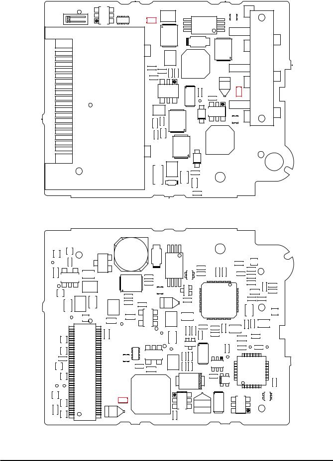
3-6.Mounted Parts Diagrames
3-6-1.MAIN PWB ASSY
CN101
Q101 |
D102 |
Q102 |
|
C111R106 |
C102 |
|
|
|
|
|
|
|
|
R103 |
C110 |
|
|
|
|
|
C114 |
|
|
|
|
|
|
L101 |
|
|
|
IC102 |
||
|
C112 |
|
|
|
|
|
R101 |
C104 |
D104 |
|
|
|
|
|
|
C105 |
C106 |
|||
R102 |
C103 |
|
||||
D101 |
|
|
|
|
||
|
|
|
|
|
|
|
|
|
R104 |
C205 |
R207 |
R209 |
|
|
|
C107 R105 |
|
|
|
|
|
IC101 |
R236 |
|
IC204 |
IC203 |
|
|
C108 |
|
|
|
|
|
|
|
|
|
R238 |
R237 |
|
|
|
|
|
JP201 |
L202 |
|
SW201 |
|
D201 |
C210 |
|
C208 |
C213 |
|
|
|
|
|
|
|
|
|
TL201 |
|
|
|
|
|
|
|
|
|
|
CN151 |
|
|
|
|
C151 |
R153 |
R155R160 |
R161R151 |
|
|
|
|
C101 |
TL212TL213 |
D212 |
|
IC208 |
|||
|
TL217TL218 |
C238 |
||||||
|
|
|
|
|
|
|
C239 |
|
|
C109 |
TL215 |
C240 |
R215 |
R217 |
C237 |
|
|
|
|
|
|
|
|
C229 |
||
|
TL211 |
TL214 |
D206 |
|
|
|
||
|
|
|
|
C233 |
R221 |
|||
|
|
|
|
|
||||
TP101 |
|
|
C223 |
|
|
X202 |
R226 |
|
C217 |
R231 |
|
C234 |
R224 |
R220 |
|||
|
|
|
C224 |
R225 |
R219 |
|||
R235
L204
|
|
|
C206 |
|
|
|
|
|
Q201 |
X201 |
|
|
R206 |
|
|
|
|
|
|
C230 |
C221 |
R214 |
C220 |
C225 |
|
|
|
|
C226 |
|
JP202 |
C216 |
L203 |
C219 |
|
IC205
D210
C212
C215
TL210 |
|
|
|
|
|
C232 |
|
|
|
|
|
|
|
|
|
|
|
C236 |
|
FB205 |
|
D203 |
|
FB201 |
|
|
|
|
|
JP204 |
R210 |
C203 |
R202 |
||
|
|
|
|
|
TP201 |
||||||
R211 |
|
|
|
|
|
C227 |
R239 |
|
|
|
|
R212 |
|
|
|
|
|
JP203 |
|
|
|
|
|
|
|
|
|
|
|
|
|
|
|
|
|
FB202 |
|
|
|
|
|
R223 |
D301 |
|
C231 |
|
IC202 |
|
|
|
|
|
|
|
|
|
|||
|
|
|
IC206 |
|
|
FB204 |
|
|
|
||
TP209TP208 |
|
|
|
|
D202 |
|
R201 |
|
|
||
|
|
|
|
|
FB203 |
|
|
|
|||
|
|
|
|
|
|
|
|
|
C241 |
|
|
TP207 |
|
|
|
|
|
R222 |
C207 |
R208 |
|
|
|
|
|
|
|
|
|
|
|
|
|||
|
|
|
|
|
|
D208 |
R204 |
CN202 |
|||
|
|
|
|
|
|
|
|
||||
|
|
|
|
|
|
|
|
|
|||
|
|
|
|
|
|
|
|
|
|
||
TL220 |
C222 |
|
TP204 |
R213 |
TP205 |
TP206 |
|
|
|
|
|
|
|
C218 |
|
R216 |
C228 |
|
|
|
|
|
|
SIDE-A
TL209 |
|
|
TL208 |
C214 |
|
|
|
L201 |
|
|
|
TP202 |
TL205 |
C209 |
|
|
|
|
X101 |
C125 |
|
|
|
|
R114 R116 |
|
IC104 |
FB111 |
R117 |
||
TP111 |
C117 |
|
R108 FB101 |
FB102 |
|
C128 |
|
R109 |
|
|
|
C119 |
|
|
|
TP102 |
C118 |
|
|
C115 |
C116 |
|
|
R107 |
|
|
|
TP103 |
|
|
|
79 G201
C211
|
C124 |
|
C126 |
C120 |
1 |
FB103
IC103
C113 |
D103 |
|
TL202 |
TL203 |
|
|
|
|
|
C301 |
|
|
80 |
|
|
|
|
|
|
|
|
L301 |
|
|
|
|
|
C302 |
|
|
|
|
|
C303 |
CN203 |
|
|
|
C305 |
|
|
|
|
|
||
|
|
|
|
|
R158 |
|
|
|
|
|
Q151 |
|
|
2 |
|
|
|
|
|
|
|
|
R159 |
|
C122 |
|
TP112 TP110 TP109 TP108 |
||
R111 |
|
FB110 |
|
|
|
|
R113 |
|
|
|
|
|
|
|
|
|
|
|
|
|
L102 |
TP106 |
|
|
|
|
C121 |
|
|
|
|
|
|
C123 |
C127 |
R115 |
|
TP113 |
TP104 TP105 |
TP107 |
|
|
|
|
|
|
|
TP303 |
TP307 |
TP306 |
|
TP304TP305 |
C306 |
|
C308 |
|
R306 |
||||||
|
|
|
|
|
|
R305 |
|
|
|
|
C310 |
|
R303 |
|
|
TP302 |
|
|
|
|
|
|
|
IC301
R301
TP310 |
TP309 |
TP311 |
TP301 TP312 |
TL219 |
|
R304 |
C307 |
||
C155 |
C156 |
|
|||||||
|
|
|
|
|
|
R302 |
|
|
|
|
|
TL216 |
|
D211 |
|
|
|
|
|
L151 |
L152 |
|
|
R228 |
|
|
|||
|
|
|
|
|
|
|
|
||
|
D154 |
|
|
2 |
Q205 |
|
|
|
|
C154 |
|
|
|
3 |
|
|
|||
|
R157 |
1 |
|
|
|
|
|
||
|
|
|
|
|
|
|
|
||
|
|
|
|
|
R234 |
|
|
|
|
|
|
|
|
|
|
R156 |
|
|
|
|
IC151 |
|
|
|
|
|
|
|
|
|
|
|
|
|
|
|
C153 |
|
|
D152 |
|
|
|
|
R154 |
|
|
|
|
|
|
|
|
|
|
|
|
||
|
C152 |
|
|
D151 |
|
|
|
||
|
|
|
|
|
|
|
|||
X301 |
|
|
|
|
|
|
TP308 |
|
R310 |
|
|
|
|
|
|
R309 |
C312 |
C313 |
R313 |
|
|
|
R307 |
|
TL302 |
||
|
|
R308 |
|
TL301 |
||
|
C311 |
|
|
TP210 |
||
C309 |
TP314 |
TP313 |
D207 |
|
||
|
|
|||||
|
|
|
|
|||
|
|
|
|
R203 |
||
|
|
|
|
Q202 |
1 |
|
|
|
|
3 |
2 |
||
|
|
|
|
|
|
|
IC207 |
|
|
|
R218 |
|
|
|
|
R227 |
|
|
||
|
|
|
|
|
||
|
|
|
|
D209 |
|
|
|
|
|
|
D204 |
|
|
C235 |
|
TP203 |
C201 |
C202 |
||
|
|
|
|
|
|
|
IC201 |
|
|
|
R205 |
||
|
|
|
C204 |
|||
|
|
|
|
|||
FB301
|
TL207 |
|
TL304 |
|
JP301 |
|
C304 |
TL303 |
TL222 |
CN201
SIDE-B
25
3.Schematics |
Fine Pix F710 SERVICE MANUAL |
|
|
3-6-2.DC PWB ASSY
|
Q408 |
|
|
L403 |
G401 |
R430 |
|
|
|
F401 |
|
|
||
|
|
|
|
C422 |
20 |
|
|
|
|
19 |
|
|
|
|
18 |
|
|
|
L410 |
|
|
R426 |
JP409 |
C434 |
|
|
|
|
|
|
|
C432 |
|
|
|
|
|
|
IC403 |
CN401 |
L409 |
|
|
||
|
C425 |
R418 |
|
R419 |
R422 |
3 |
|
|
2 |
|
|
1 |
|
|
L408
C435
D407
|
|
|
|
R416 |
|
|
Q405 |
|
|
|
|
|
|
1 |
|
D406 |
|
|
|
|
|
|
|
C433 |
L407 |
|
|
CN501 |
|
R425 |
|
|
|
|
|
|
|
2 |
|
|
|
|
|
C423 |
C436 |
R429 |
TP408 |
R415 |
F403 |
|
|
|
|
|
|
D404 |
Q403 |
3 |
|
|
|
|||
C429 |
|
|
|
R413 |
|
|
|
|
|
|
|
|
L405 |
|
C427 |
|
|
|
|
|
D405 |
|
|
Q501 |
C431 |
R420 |
|
|
|
R423 |
|
|
|
|
|
|
|
|
|
|
R424 |
|
|
|
SIDE-A
TL409 |
TL401 |
|
|
|
L406 |
|
D403 |
|
|
|
|
|
|
|
TP405 |
C441 |
|
|
Q406 |
|
|
|
Q402 |
|
|
|
|
|
|
|
|
|
|
|
|
|
|
|
|
|
|
|
C402 |
|
C444 |
|
|
|
|
|
|
|
|
|
|
|
C405 |
|
|
IC404 |
|
C439 |
|
|
|
R421 |
|
|
|
|
|
R403 |
||
|
|
|
|
|
|
|
|
|
|
|
||||
|
|
|
|
|
|
|
|
|
|
|
|
|
||
|
|
|
|
|
|
|
|
|
|
|
|
|
|
|
|
|
|
L413 |
|
C426 |
|
JP408 |
|
|
|
|
|
|
|
|
|
|
|
|
|
R412 |
|
|
D401 |
1 |
|
|
||
|
TL402 |
|
|
|
|
|
|
3 |
2 |
|
|
|||
|
|
|
|
|
|
|
|
|
|
|
|
|
|
|
|
|
|
C449 |
|
R417 |
|
|
|
|
JP405 |
|
|
||
|
C440 |
L411 |
L412 |
C428 |
|
|
C421 |
|
|
|
||||
|
C443 |
|
|
|
|
|
|
|
||||||
|
|
|
|
|
|
|
|
|
|
|
|
|||
|
|
|
|
|
|
|
|
|
|
|
|
|
|
|
|
TP404 |
|
TL405 |
C438 |
C446 |
|
IC406 |
L402 |
|
C410 |
|
|
||
|
|
|
|
|
|
|
|
|||||||
|
|
|
|
|
|
|
|
|
|
|
|
|||
|
|
|
|
TP403 |
|
|
|
|
|
|
|
|
|
|
|
|
1 |
2 |
|
|
|
|
|
|
|
|
|
R406 |
|
|
|
|
|
|
|
|
|
|
1R407 |
C416 |
||||
|
TL410 |
JP410 |
|
|
TP401 |
C424 |
|
|
C415 |
|||||
|
|
|
|
|
2 |
|||||||||
|
|
|
|
|
|
|
|
|
|
|
Q401 |
|
||
|
TL412 |
|
|
|
|
R431 |
|
TP402 |
C420 |
|
R4113 |
C430 |
||
|
|
|
|
R432 |
IC405 |
|
|
|||||||
|
C450 |
|
|
|
|
|
|
|
|
|
|
|
||
|
|
|
|
|
|
L404 |
R409 |
|
R410 |
|
||||
TL408 |
CN402 |
|
|
C442 |
C445 |
|
|
|||||||
|
|
|
|
|
|
|
|
|
|
|
||||
|
|
|
|
|
|
|
|
|
|
|
|
|||
TP407 |
TL413 |
|
|
|
|
|
|
|
|
|
|
|
||
|
|
|
|
|
|
|
|
|
D402 |
|
||||
|
|
|
|
|
|
|
|
|
|
|
|
|||
TL414 |
TP406 |
|
|
|
|
|
L401 |
|
IC402 |
|
|
|
|
C418 |
TL404 |
|
|
|
|
|
|
|
|
|
|
||||
|
|
|
|
|
F402 |
|
|
|
|
|
|
|
|
|
C447 |
TL403 |
79 |
80 |
C409 |
|
|
|
R404 |
|
|
|
|
|
|
SIDE-B
|
|
R401 |
TL407 |
|
|
|
|
|
|
|
|
||
R402 |
C401 |
|
|
JP401 |
|
|
|
C403 |
JP402 |
|
|
||
|
|
|
|
|
|
|
|
|
|
|
JP403 |
JP404 |
C448 |
|
|
|
|
|
||
|
|
|
|
|
|
|
|
|
|
|
C404 |
|
R433 |
IC401 |
|
|
|
C406 |
C407 |
|
|
|
|
C408 |
|
TL406 |
|
|
C417 |
C413 |
R408 |
C412 |
C411 |
|
|
|
|
|
|
|
|
R405 |
|
|
|
|
|
|
C414 |
|
|
|
JP406 |
|
|
|
|
|
JP407 |
|
||
|
|
|
TP501 |
TP502 |
|
|
|
C503 |
|
|
|
||
|
|
R502 |
C502 |
|
||
|
|
|
|
|
|
|
|
|
TP503 |
|
|
|
|
Q404 |
|
|
|
|
|
|
|
|
|
|
IC502 |
|
|
R414 |
D501 |
|
|
|
|
|
|
|
|
|
|
R501 |
|
|
|
|
|
|
|
|
C419 |
|
|
|
|
C501 |
|
|
|
IC501 |
|
|
|
|
26
Loading...