


Stylus Pro GS6000
Table of contents
 Loading...
GS6000 Field Repair Guide 10/10/08
Printer Component, Software Item, LCD Display, Printer Button Page 1.
Table of Contents
Table of Contents - - - - - - - - - - - - - - - - - - - - - - - - - - - - - - 1
Control Panel Map - - - - - - - - - - - - - - - - - - - - - - - - - - - - - 5
Component Replacement - - - - - - - - - - - - - - - - - - - - - - - - - - 12
Board (Heater Control) Removal - - - - - - - - - - - - - - - - - - - - - - - - - 13
Board (Heater Relay) Removal - - - - - - - - - - - - - - - - - - - - - - - - - - 15
Board (Main) Removal - - - - - - - - - - - - - - - - - - - - - - - - - - - - - - 17
Board (Main) Installation - - - - - - - - - - - - - - - - - - - - - - - - - - - - - 24
Board (Power Supply) Removal - - - - - - - - - - - - - - - - - - - - - - - - - 35
Board (P/S Term) Removal - - - - - - - - - - - - - - - - - - - - - - - - - - - 38
Board (Sub B) Removal - - - - - - - - - - - - - - - - - - - - - - - - - - - - - 40
Board (Sub C) Removal - - - - - - - - - - - - - - - - - - - - - - - - - - - - - 42
Board Sub D (Left) Removal - - - - - - - - - - - - - - - - - - - - - - - - - - - 44
Board Sub D (Right) Removal - - - - - - - - - - - - - - - - - - - - - - - - - - 47
Cap Assy Removal - - - - - - - - - - - - - - - - - - - - - - - - - - - - - - - - 50
Cleaner Removal - - - - - - - - - - - - - - - - - - - - - - - - - - - - - - - - - 54
Cover (Control Panel) Removal - - - - - - - - - - - - - - - - - - - - - - - - - 57
Cover (Front Left) Removal - - - - - - - - - - - - - - - - - - - - - - - - - - - 61
Cover (Ink Bay Left) Removal - - - - - - - - - - - - - - - - - - - - - - - - - - 64
Cover (Ink Bay Right) Removal - - - - - - - - - - - - - - - - - - - - - - - - - 68
Cover (Rear) Removal - - - - - - - - - - - - - - - - - - - - - - - - - - - - - - 72
Cover (Side Left) Removal - - - - - - - - - - - - - - - - - - - - - - - - - - - - 73
Cover (Side Right) Removal - - - - - - - - - - - - - - - - - - - - - - - - - - - 76
Cover (Top Left) Removal - - - - - - - - - - - - - - - - - - - - - - - - - - - - 79
Cover (Top Right) Removal - - - - - - - - - - - - - - - - - - - - - - - - - - - 81

GS6000 Field Repair Guide 10/10/08
Printer Component, Software Item, LCD Display, Printer Button Page 2.
Flushing Box Removal - - - - - - - - - - - - - - - - - - - - - - - - - - - - - - 83
Heater Assembly (Platen) Removal - - - - - - - - - - - - - - - - - - - - - - - 86
Heater Assembly (Post) Removal - - - - - - - - - - - - - - - - - - - - - - - - 90
Heater Assembly (Pre) Removal - - - - - - - - - - - - - - - - - - - - - - - - - 98
Media Holder Assembly Removal - - - - - - - - - - - - - - - - - - - - - - - -102
Print Head (Left) Removal - - - - - - - - - - - - - - - - - - - - - - - - - - - -103
Print Head (Left) Installation - - - - - - - - - - - - - - - - - - - - - - - - - - -122
Print Head (Right) Removal - - - - - - - - - - - - - - - - - - - - - - - - - - -138
Print Head (Right) Installation - - - - - - - - - - - - - - - - - - - - - - - - - -159
Pump Assembly Removal - - - - - - - - - - - - - - - - - - - - - - - - - - - -177
Sensor (Rear AD) Removal - - - - - - - - - - - - - - - - - - - - - - - - - - -182
Troubleshooting - - - - - - - - - - - - - - - - - - - - - - - - - - - - - - 185
Error Codes (Service) - - - - - - - - - - - - - - - - - - - - - - - - - - - - - -186
Sub Tank Troubleshooting - - - - - - - - - - - - - - - - - - - - - - - - - - -196
Adjustments - - - - - - - - - - - - - - - - - - - - - - - - - - - - - - - 198
All Counter Clear - - - - - - - - - - - - - - - - - - - - - - - - - - - - - - - -199
Check Network Communication - - - - - - - - - - - - - - - - - - - - - - - - -200
CR Motor Life Counter Save & Reset - - - - - - - - - - - - - - - - - - - - - -204
Head Slant (CR) Adjustment - - - - - - - - - - - - - - - - - - - - - - - - - - -207
Feed Adj.+Side Adjustment - - - - - - - - - - - - - - - - - - - - - - - - - - -213
Head L [M,C,K,Y] Life Counter Save & Reset - - - - - - - - - - - - - - - - - -215
Head R [O,G,Lc,Lm] Life Counter Save & Reset - - - - - - - - - - - - - - - - -218
Head Rank Input - - - - - - - - - - - - - - - - - - - - - - - - - - - - - - - - -221
Head Wiping Counter Reset - - - - - - - - - - - - - - - - - - - - - - - - - - -224
Ink Discharge - - - - - - - - - - - - - - - - - - - - - - - - - - - - - - - - - -227
Initial Ink Charge Flag - - - - - - - - - - - - - - - - - - - - - - - - - - - - - -230

GS6000 Field Repair Guide 10/10/08
Printer Component, Software Item, LCD Display, Printer Button Page 3.
Input Serial Number - - - - - - - - - - - - - - - - - - - - - - - - - - - - - - -233
NVRAM.EXE - - - - - - - - - - - - - - - - - - - - - - - - - - - - - - - - - - -236
PF Motor Life Counter Save & Reset - - - - - - - - - - - - - - - - - - - - - -245
Pump Motor 1 [Front] Life Counter Reset - - - - - - - - - - - - - - - - - - - -248
Pump Motor 2 [Rear] Life Counter Reset - - - - - - - - - - - - - - - - - - - -251
RTC & USB ID Adjustment - - - - - - - - - - - - - - - - - - - - - - - - - - - -254
Washing Sequence Flag - - - - - - - - - - - - - - - - - - - - - - - - - - - - -257
Component Pictures - - - - - - - - - - - - - - - - - - - - - - - - - - - 260
Board (Heater Control) Picture - - - - - - - - - - - - - - - - - - - - - - - - -261
Board (Heater Relay) Picture - - - - - - - - - - - - - - - - - - - - - - - - - -262
Board (Main) Picture - - - - - - - - - - - - - - - - - - - - - - - - - - - - - - -263
Board (Power Supply) Picture - - - - - - - - - - - - - - - - - - - - - - - - - -264
Board (P/S Term) Picture - - - - - - - - - - - - - - - - - - - - - - - - - - - -265
Board (Sub-B) Picture - - - - - - - - - - - - - - - - - - - - - - - - - - - - - -266
Board (Sub C) Picture - - - - - - - - - - - - - - - - - - - - - - - - - - - - - -267
Board (Sub-D) Picture - - - - - - - - - - - - - - - - - - - - - - - - - - - - - -268
Cap Assembly Picture - - - - - - - - - - - - - - - - - - - - - - - - - - - - - -269
Control Panel Pictures - - - - - - - - - - - - - - - - - - - - - - - - - - - - - -270
Flushing Box Picture - - - - - - - - - - - - - - - - - - - - - - - - - - - - - -271
Print Head Pictures - - - - - - - - - - - - - - - - - - - - - - - - - - - - - - -272
Pump Assembly - - - - - - - - - - - - - - - - - - - - - - - - - - - - - - - - -274
Sensor (Rear AD) Picture - - - - - - - - - - - - - - - - - - - - - - - - - - - -275
Reference - - - - - - - - - - - - - - - - - - - - - - - - - - - - - - - - 276
Accessories List - - - - - - - - - - - - - - - - - - - - - - - - - - - - - - - - -277
Carriage Release (Manual) - - - - - - - - - - - - - - - - - - - - - - - - - - - -278
Cleaning Supplies - - - - - - - - - - - - - - - - - - - - - - - - - - - - - - - -279

GS6000 Field Repair Guide 10/10/08
Printer Component, Software Item, LCD Display, Printer Button Page 4.
Color Order - - - - - - - - - - - - - - - - - - - - - - - - - - - - - - - - - - -280
Connectors / Wiring - - - - - - - - - - - - - - - - - - - - - - - - - - - - - - -282
Consumable/Service Parts List - - - - - - - - - - - - - - - - - - - - - - - - -292
Firmware History - - - - - - - - - - - - - - - - - - - - - - - - - - - - - - - -294
Firmware Update Procedure Using FWUpdate.exe - - - - - - - - - - - - - - -295
Glossary - - - - - - - - - - - - - - - - - - - - - - - - - - - - - - - - - - - - -296
Ink Draining and Flushing Procedure - - - - - - - - - - - - - - - - - - - - - -302
Revision History - - - - - - - - - - - - - - - - - - - - - - - - - - - - - - - - -304
Sensors, Motors, Solenoids, and Fans - - - - - - - - - - - - - - - - - - - - -305
Service Tools - - - - - - - - - - - - - - - - - - - - - - - - - - - - - - - - - -308
Utilities - - - - - - - - - - - - - - - - - - - - - - - - - - - - - - - - - - 309
FWUpdate.exe - - - - - - - - - - - - - - - - - - - - - - - - - - - - - - - - - -310
Servprog.exe - - - - - - - - - - - - - - - - - - - - - - - - - - - - - - - - - - -314
GS6000 Field Repair Guide 10/10/08
Printer Component, Software Item, LCD Display, Printer Button Page 5.
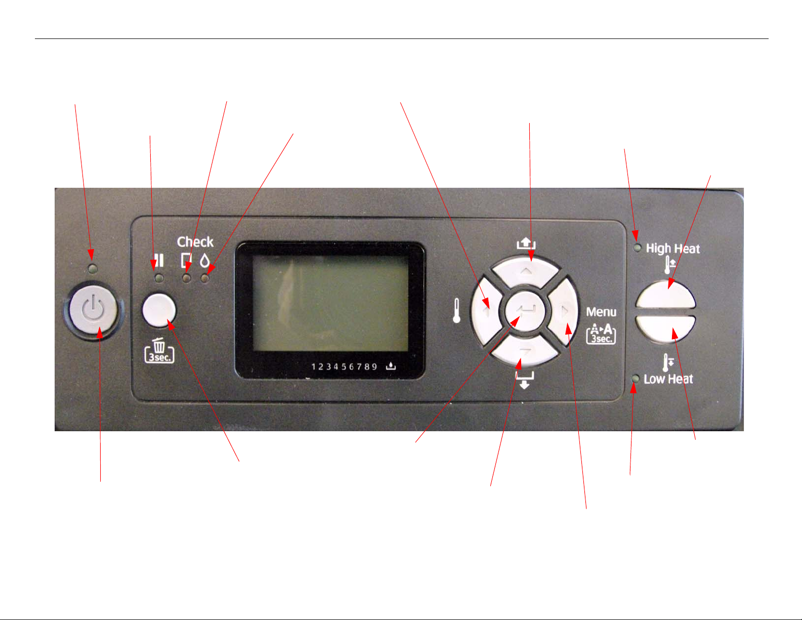
Control Panel Map
Power Light
Paper Check Light
Ink Check Light
Heater and Left Arrow
Paper Feed (Reverse) and Up Arrow
Pause and Reset
Paper Feed (Forward) and Down Arrow
Pause Light
Low Heat Light
Power Button
Enter
Low Heat
High Heat Light
High Heat
Menu and Right Arrow
GS6000 Field Repair Guide 10/10/08
Printer Component, Software Item, LCD Display, Printer Button Page 6.
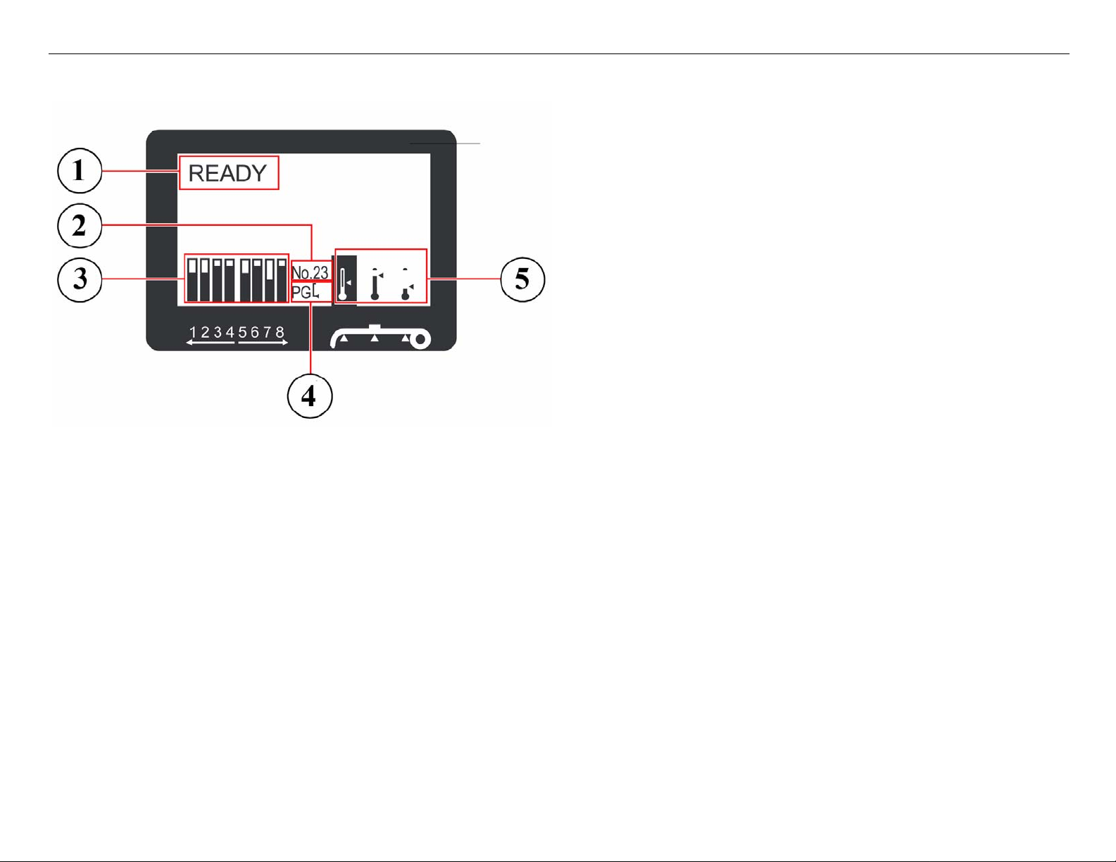
Printers LCD Display
1. Messages
2. Paper Type
3. Ink Cartridge Status Icon
4. Platen Gap Icon
5. Heater Icon
Maintenance Mode: Pause, at power on.
F/W DOWNLOAD MODE: Up, Down, Left, and Right, at power on.
Parameter Backup and Restore Mode: Down, Right, and Pause, at power on.
SERVICEMAN MODE: Down, Right, and Pause, at power on.

GS6000 Field Repair Guide 10/10/08
Printer Component, Software Item, LCD Display, Printer Button Page 7.
User Menu: Press the Menu button when the printer displays Ready
1. PRINTER SETUP.
Side Margin: *5mm-25mm(*0.2inch-1.00inch)
Paper Size Check: *ON, OFF
Paper Skew Check: *ON, OFF
Print Nozzle Pattern: *OFF, On: Every PageOn: Every 10 Pages
Heating Time: Off, *10min-240min
Flush onto Paper: *Yes, No
Flushing Frequency: 1Pass-*5Pass-999Pass
Paper Origin Setup: *0mm-800mm, *0-32inches
Auto Take-Up Reel: *On, Off
Head Fan: *ON, OFF
Regular Cleaning: Off, 1h-*6h, 9h, 12h, 18h, 24h
Initialize Settings: Execute
2. Paper Setup
Paper Type: *Standard, No. 1 - 30
Paper Setup: *Standard, No. 1-30: Print Mode: *Speed 2, Speed 1-3, Quality 1-3, Max Quality
Paper Feed Adjust: Line Feed Adjust: 100mm, 250mm, 500mm: Print
Print Sample Pattern
Head Alignment: Bi-D All
Pre Heater: *50C, Off, 30-50C
Platen Heater: *50C, Off, 30-50C
After Heater: *50C, Off, 30-50C
M/W Adjust: *High A, High A-D, Extra High A-B, Low A-B, Medium A-D
Paper Suction: *High, Low
Drying Time: *0.0sec, 0-10.0 sec.
Carriage Movement: *Date Width, Printer Full Width
Print Multiple Layer: *Off, 2-8

GS6000 Field Repair Guide 10/10/08
Printer Component, Software Item, LCD Display, Printer Button Page 8.
Maintenance Mode: Press and hold the Pause button and turn on the Printer.
LANGUAGE: *ENGLISH, JAPANESE, FRENCH, GERMAN, ITALIAN, PORTUGUE, SPANISH, DUTCH
(Panel Language)
UNIT: *FEET/INCH, METER (Set’s the unit of measure that the printer displays)
Thermometer Unit: *C, F (Set the Unit for Temperature of Heaters)
DEFAULT PANEL: EXEC (Resets to Factory Default all of the User Menus
3. Maintenance
Cleaning (Very Light): Execute
Cleaning (Light): Execute
Cleaning (Medium): Execute
Cleaning (Heavy): Execute
Head Washing: Execute
Carriage Maintenance: Execute
Clocking Setting: MM/DD/YY HH MM
Contrast Adjustment: -20 - *0 - 20
4. Test Print
Nozzle Check: Print
Status Print: Print
Network Status Sheet: Print
Job Information: Print
Custom Paper: Print
5. Printer Status
Version: T0xxxx-xx xx IBCC
Printable Page: (ink color) nnnnn Pages
Ink Level: (ink colors) nn%
Usage Counter: Ink xxxxx.x ml, Paper xxxxx.x cm
Clear Usage Count: Ink: Execute
Paper: Execute
Job History
Total Print: nnnnnn Pages
EDM Status: *Not Started, Enabled, Disabled
Last Uploaded
MM/DD/YY HH/MM
6. Network Setup
Network Setup: *Disable, Enable
IP Address Setting:*Auto, Panel
IP, SM, DG Setting: IP Address:*192.168.192.168
Subnet Mask:*255.255.255.000
Default Gateway:
*255.255.255.255
Bonjour: *On, Off
Init Network Setting: Execute

GS6000 Field Repair Guide 10/10/08
Printer Component, Software Item, LCD Display, Printer Button Page 9.
ServiceMan Mode: Press and hold the Down, Right, and Pause buttons, and turn on the Printer
Note: SERVICEMAN MODE turns on the USB Port even if there is an error condition.
SELF TESTING:
Test:
Version: F/W, Boot, Pram1, Pram 2, Serial No., USB, Serial No.
Panel: Key, LCD, LED, Printer Check LED(Button, LCD, and LED tests for the control panel)
Sensor: Paper Lever: Down, Up (Paper Release Sensor test)
MTank: On, ON, ON(CSIC Contact Test)
Carriage NOT: 1,2,3,4,5,6,7,8 (Ink Cartridge Sensor test for 9 Ink Bays)
RearAD: (nnn nnn) (Rear Paper Sensor test)
Head Temp: (nn)C (Displays the current Print Head temperature in degrees centigrade)
Drv. Temp: (nn)C (Displays the current Print Head Driver temperature in degrees centigrade)
PG: (High, Low) (Platen Gap Sensor Test)
CR Origin: (Home Position Sensor Test)
Edge AD: (Edge Detector Sensor Test)
Encoder: CR (nnnn) (Carriage Encoder test. Counts up, moving away from home position)
PF (nnnn) (Paper Feed Encoder test. Counts up, as the paper advances.)
Fan: Paper(ALL): (Fan test for all paper suction fans)
Paper(Duty): (200% - 0%) (Tests the fan suction for all paper suction fans)
Paper1: (Fan test for paper suction fan #1 (Right Side Fan))
Paper2: (Fan test for paper suction fan #2
Paper3: (Fan test for paper suction fan #3
Paper4: (Fan test for paper suction fan #4
HT Fan: (Fan test for the Head Driver Cooling Fan)
Head Fan 1: (Fan Test for the Carriage Fan 1)
Head Fan 2: (Fan Test for the Carriage Fan 2)
Actuator: CrLock Sol (Carriage Lock Solenoid Test)
Ctrl Test: Ctrl Ver: Ctrl AP, Ctrl PCB
Ctrl Sns: Tank: 1 H/L/V - 8 H/L/V
Etc: Maint Cover, Ink Cover, Front Cover, Pre Heater 1/2, Platen Heater 1/2, After

GS6000 Field Repair Guide 10/10/08
Printer Component, Software Item, LCD Display, Printer Button Page 10.
Heat 1/2
Ctrl Fan: Mist Fan: Mist Fan All, Mist Fan 1, Mist Fan 2, Mist Fan 3
Box Fan
Ctrl Heater: Pre Heater: Pre Heater 1/2
Platen Heater: Platen Heater 1/2
After Heater: After Heater 1/2
Ctrl Actuator: Tank Valve
Ink Valve: Valve1 On, Valve2 On, Valve3 On, Valve4 On
Ink Pump
Wiper
Error History (list of past errors)
Edge Sns Lvl: [Enter], Start (Sets the black level of the Edge Detector)
Adjustment
CR Origin Adjust: Exec. (Sets the “Capped” position for the Carriage Assembly.)
Platen Adjust: Exec.(Turns on the Platen Heater).
Heater Temp: Pre Heater Temp: 0-58 C (Sets the Pre Heater Temperature for service printing)
Platen Heater Temp:0-58 C (Sets the Platen Heater Temperature for service printing)
After Heater: 0-58 C (Sets the Post Heater Temperature for service printing)
RearAD: [Enter]Start (nnn nnn nnn) (For adjusting the Rear Paper Sensor)
Init.Fill: [Enter]Start (Starts a initial fill)
Nozzle Check: Output Pattern:(Nozzle Check pattern for checking vertical deflections)
Nozzle Alignment: Output Pattern: (Nozzle Check pattern for checking horizontal deflections)
Head Slant : CR Head Slant, PF Head Slant: Adjust, Confirm(Adjust Print head mechanical alignments)
Skew Check: Please Set Paper (Tests for Paper Skewing)
Feed Adj.+ Side: [Enter] Print(Performs the 980mm and Side Margin adjustments)
Gap Adj: Uni-D Low, Bi-D Low, Uni-D High, Bi-D High:
VSD1 400, VSD3 320, VSD3 400, All: Rough Adjust, Fine Adjust (Perform All, Rough, to com-
pletely adjust the Bi and Uni directional adjustments.)
Print Adj. Variable: [Enter] Print (Prints the numeric adjustment variables currently set and head rank)
All Pattern: (Print All Adjustment Patterns)

GS6000 Field Repair Guide 10/10/08
Printer Component, Software Item, LCD Display, Printer Button Page 11.
Life(?)
CR Motor: Speed CW, Speed CCW, Page Size, Head Fan, LifeCount (?)
PF Motor: Feed Amount, LifeCount(?)
Pump: Pump Speed, LifeCount(?)
Head Fan: Head Fan 1 ON Time, Head Fan 1 OFF Ti me, Head Fan 2 O N Time, Head Fan 2 OFF Time,
LifeCount(?)
CR Lock: Wait Time (sec.), LifeCount(?)
Ink Valve: Valve1 On, Valve2 On, Valve3 On, Valve4 On, Valve All On(?)
Tank Valve: Valve1 On, Valve2 On, Valve3 On, V alve4 On, Valve5 On, V alve6 On, Valve7 On, V alve8 on,
Valve All On(?)
Feed(?)
Key: Backward(?)
Key: Forward(?)
Status(?)

GS6000 Field Repair Guide 10/10/08
Printer Component, Software Item, LCD Display, Printer Button Page 12.
Component
Replacement
GS6000 Field Repair Guide 10/10/08
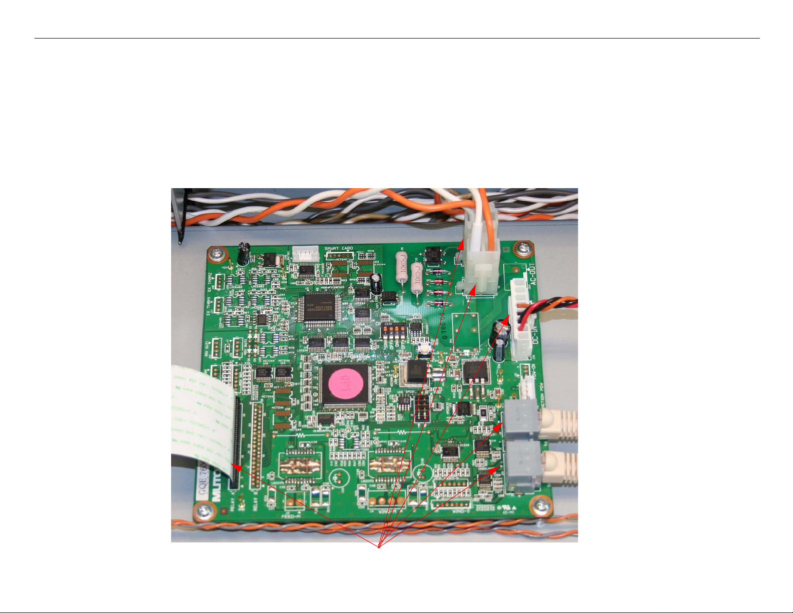
Board (Heater Control) Removal Printer Component, Software Item, LCD Display, Printer Button Page 13.
Board (Heater Control) Removal
1. Turn off the Printer and UNPLUG from AC.
2. Remove the Heater Assembly (Post).
3. Unplug the 6 Cables that attach the Heater Control Board to the Printer.
Unplug 6 Cables.
GS6000 Field Repair Guide 10/10/08
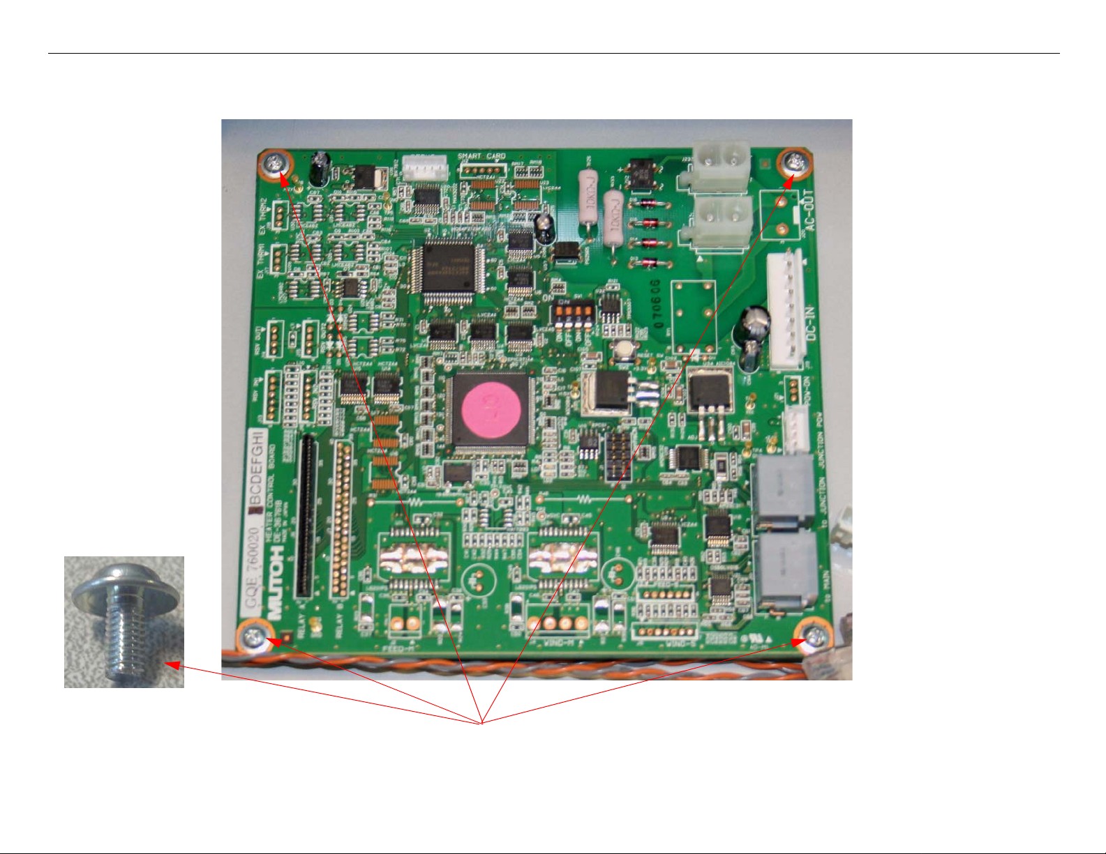
Board (Heater Control) Removal Printer Component, Software Item, LCD Display, Printer Button Page 14.
4. Remove 4 Screws that fasten the Heater Control Board to the Printer.
Remove 4 Screws.
GS6000 Field Repair Guide 10/10/08
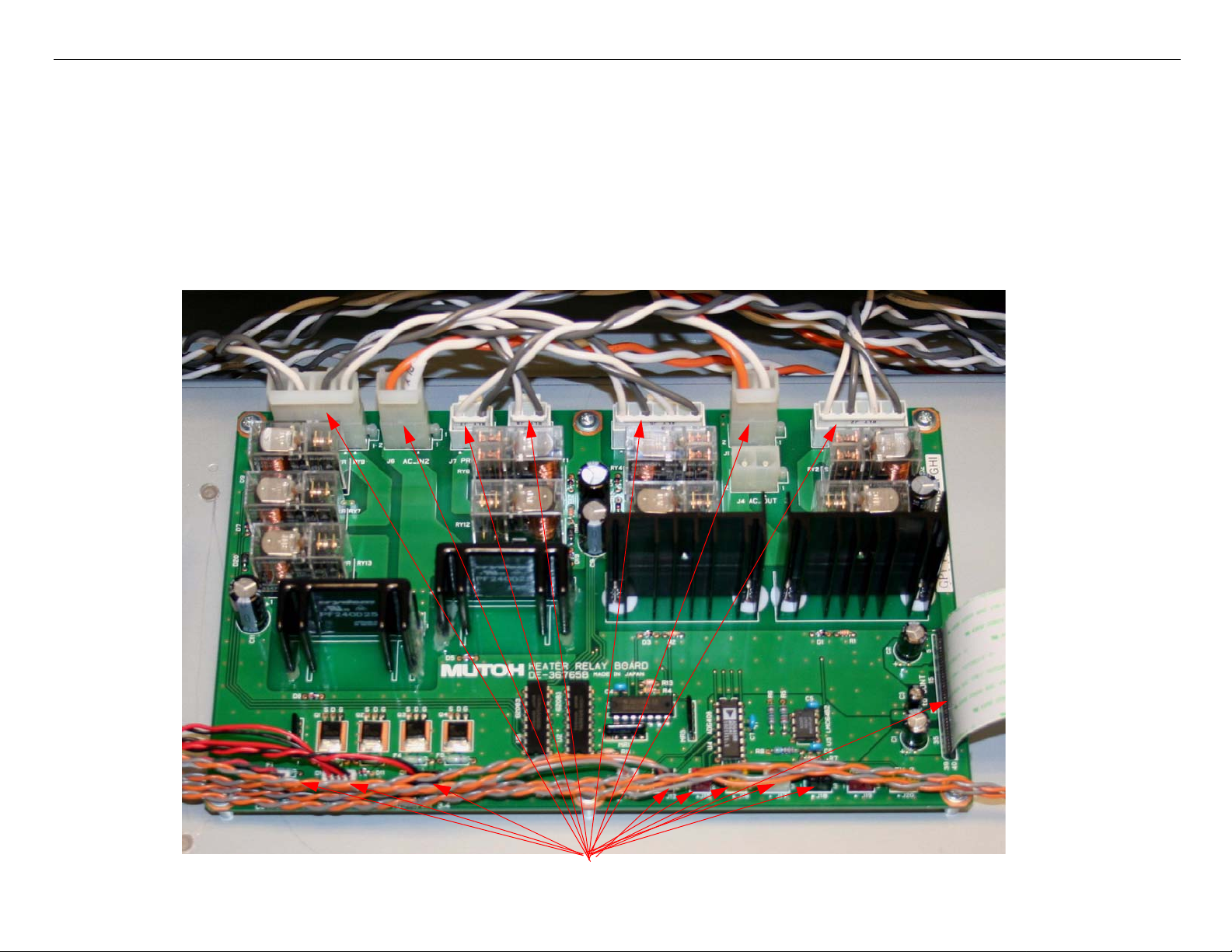
Board (Heater Relay) Removal Printer Component, Software Item, LCD Display, Printer Button Page 15.
Board (Heater Relay) Removal
1. Turn off the Printer and UNPLUG from AC.
2. Remove the Heater Assembly (Post).
3. Unplug the 17 Cables that attach the Heater Relay Board to the Printer.
Unplug 17Cables.
GS6000 Field Repair Guide 10/10/08
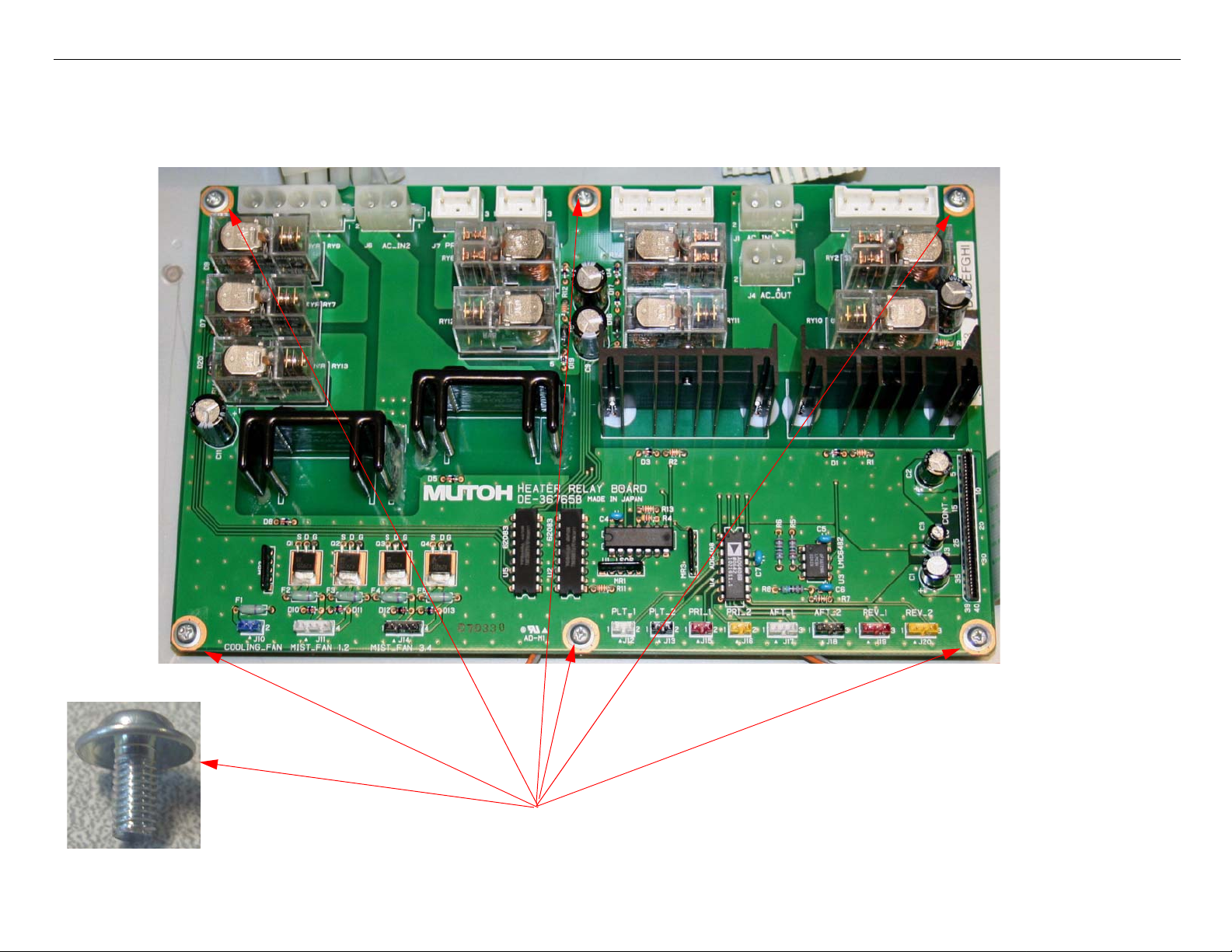
Board (Heater Relay) Removal Printer Component, Software Item, LCD Display, Printer Button Page 16.
4. Remove 6 Screws that fasten the Heater Relay Board to the Printer.
Remove 6 Screws.

GS6000 Field Repair Guide 10/10/08
Board (Main) Removal Printer Component, Software Item, LCD Display, Printer Button Page 17.
Board (Main) Removal
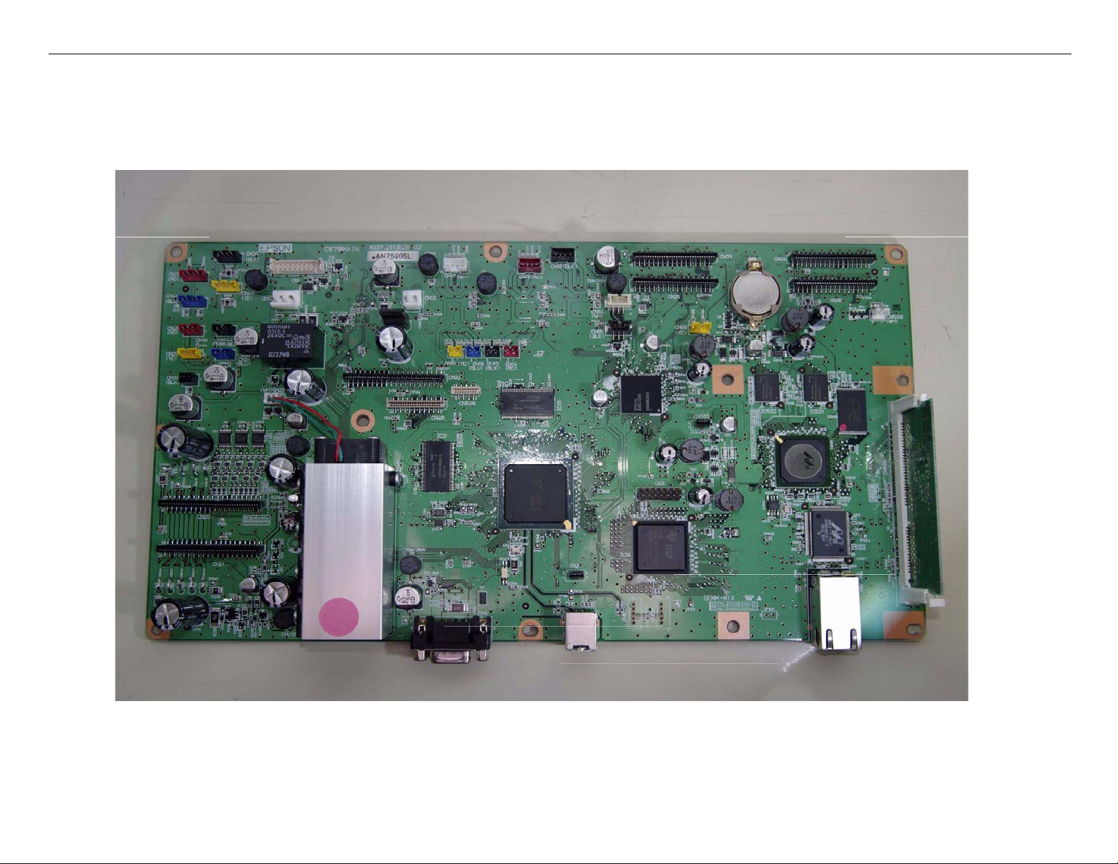
Note: GS6000 Main Board Part # 2121641 (the part # is stamped on the board)
Main Board Removal (Overview)
• Back up the Printer’s Parameters.
• Release the Mainboard (Box) Cover.
• Unplug the Cables.
• Remove the Screws.
• Remove the Ethernet Cover from the Main Board.
• Remove the Main Board
Main Board Removal (Detail)
1. Re-Install the Printer’s parameters using the NV-Ram Backup Utility feature of the servprog.exe utility.
1.1 Perform the RTC & USBID Adjustment located in the servprog.exe utility.
Note: If the Printer’s parameters can not be “backed up”, print out the Print Head Calibration value
(Head Rank). The Print Head Calibration value is included when the Adjustment variables are printed.
(ServiceMan Mode: Self Testing: Adjustment: Print Adj. Variable).
2. Turn off the Printer and UNPLUG from AC.

GS6000 Field Repair Guide 10/10/08
Board (Main) Removal Printer Component, Software Item, LCD Display, Printer Button Page 18.
3. Release the Mainboard Cover.
Remove 5 screws securing the
Mainboard Cover to the Printer.
Remove 2
screws
Be sure to hold the Mainboard Cover
when removing the last screw as the
cover will drop down.
GS6000 Field Repair Guide 10/10/08
Board (Main) Removal Printer Component, Software Item, LCD Display, Printer Button Page 19.
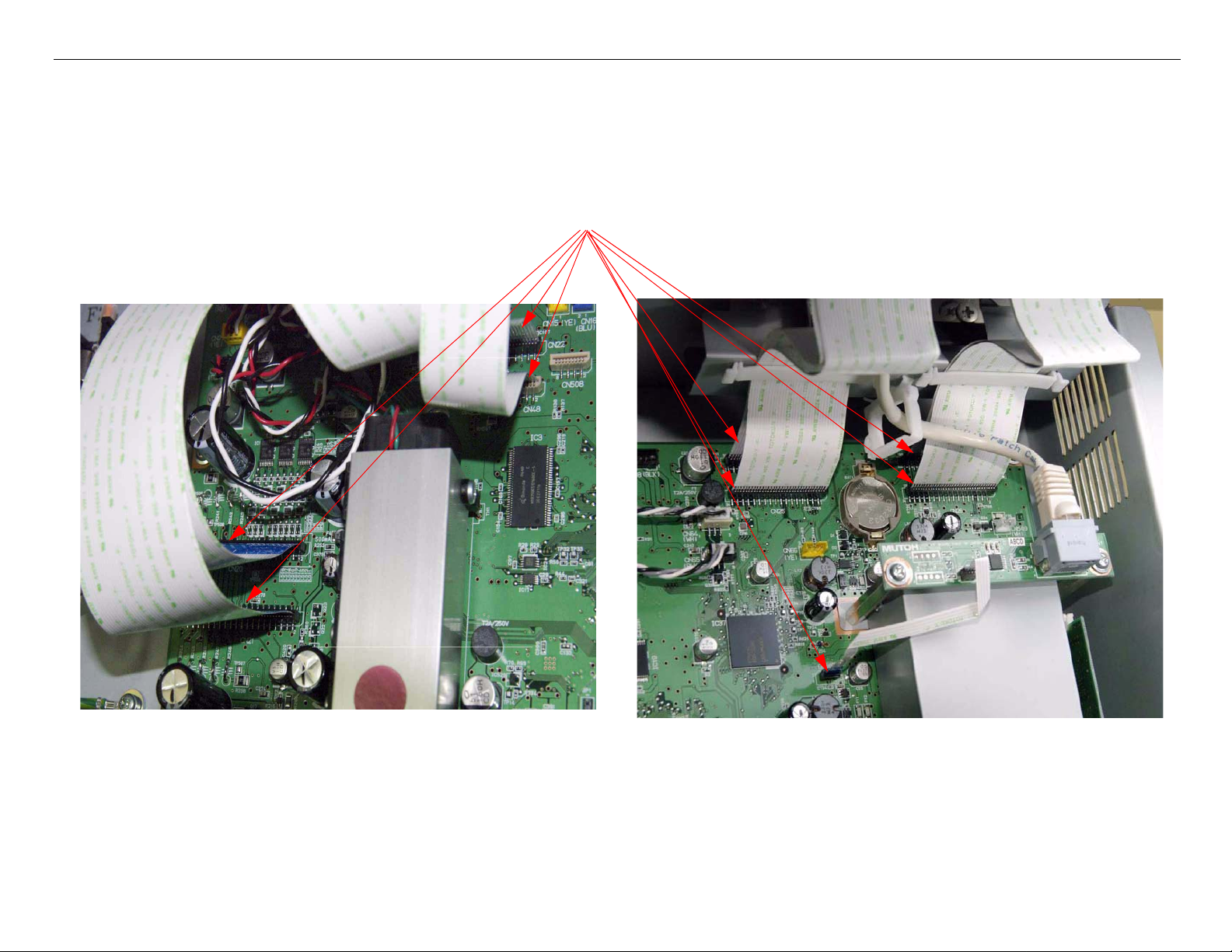
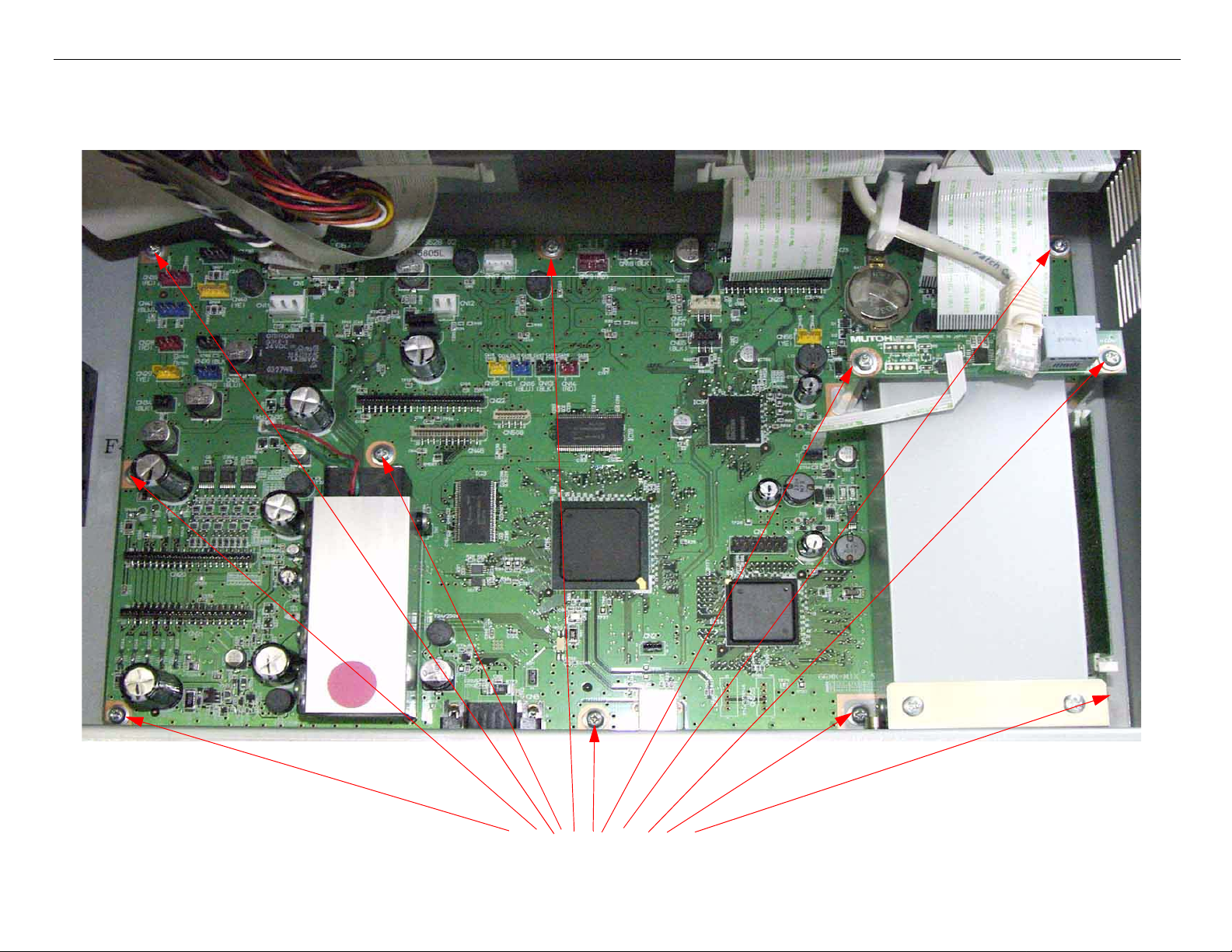
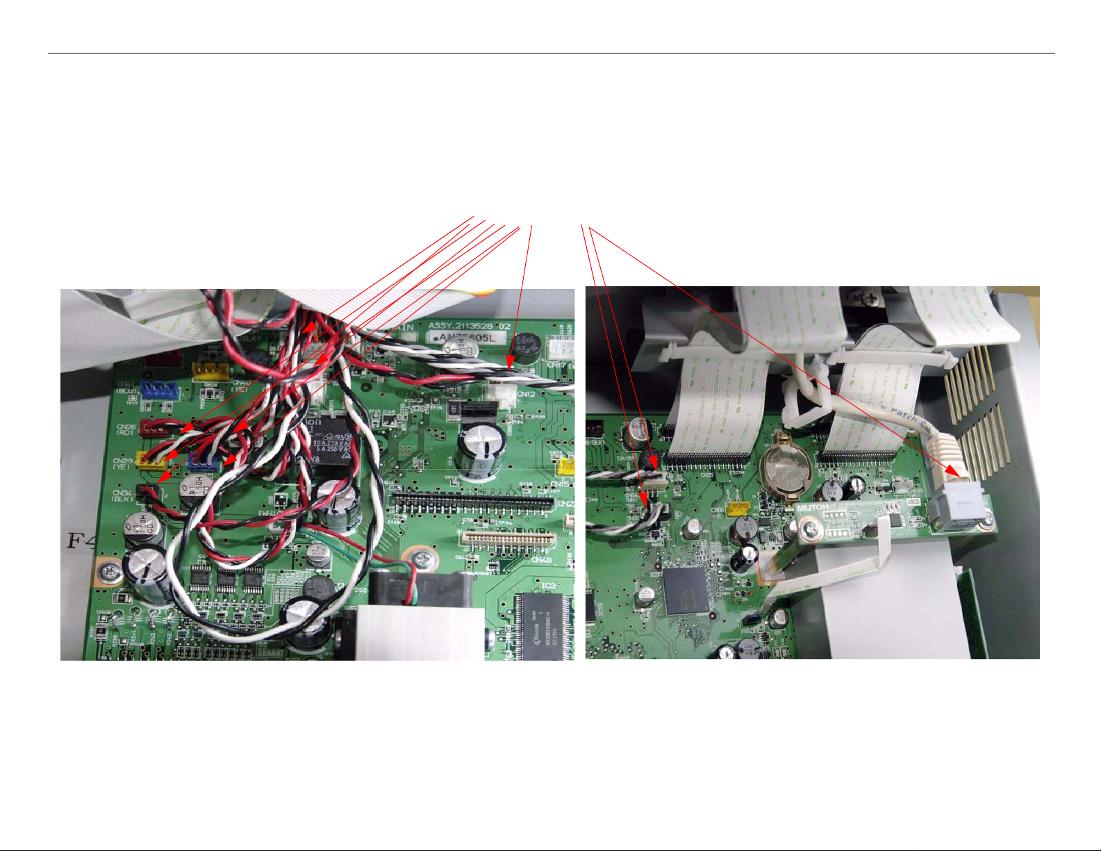
4. Unplug the 9 Foil Cables that attach the Main Board to the Printer
Unplug 9 Foil Cables
GS6000 Field Repair Guide 10/10/08
Board (Main) Removal Printer Component, Software Item, LCD Display, Printer Button Page 20.
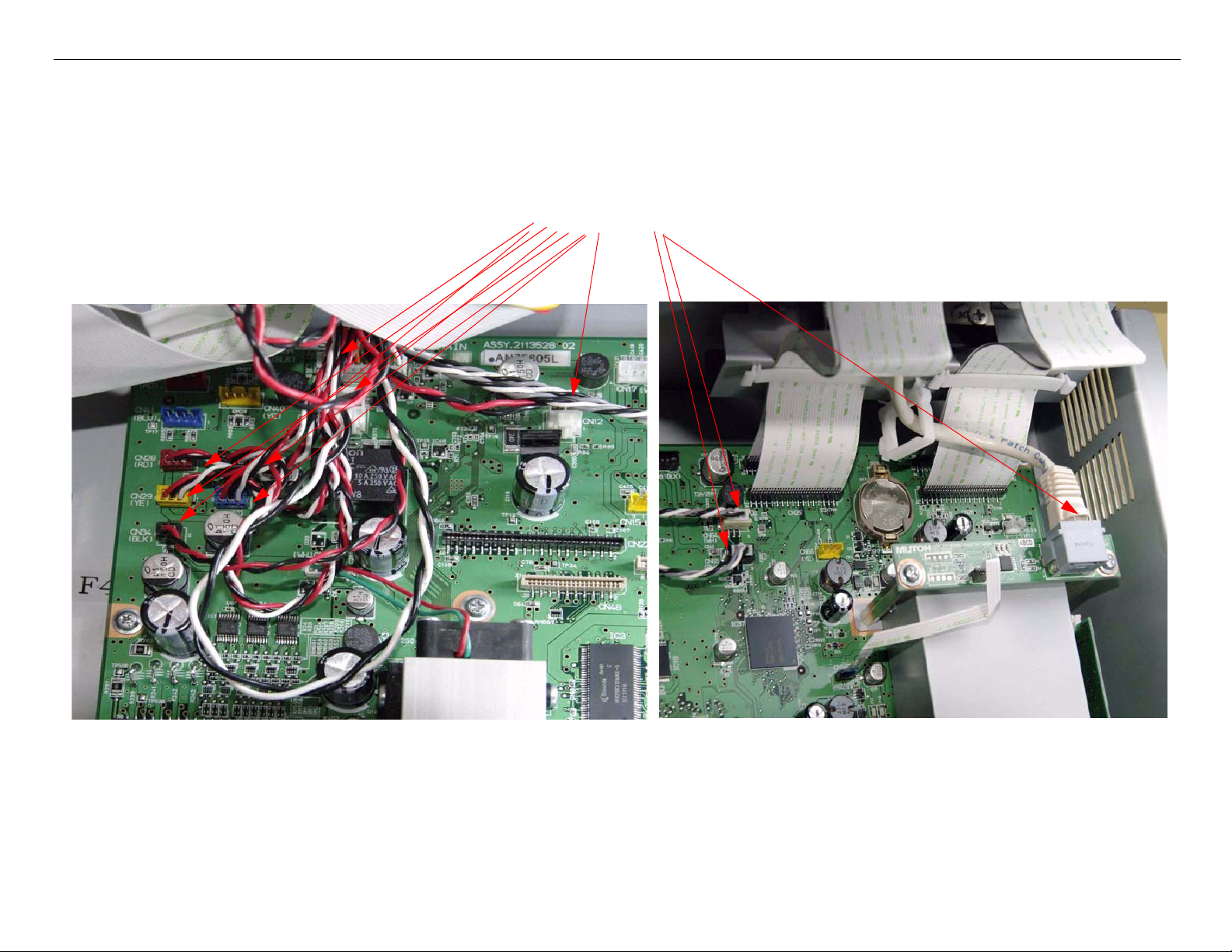
5. Unplug the 11 Wired Cables that attach the Main Board to the Printer.
Unplug 11 Wire Cables
GS6000 Field Repair Guide 10/10/08
Board (Main) Removal Printer Component, Software Item, LCD Display, Printer Button Page 21.
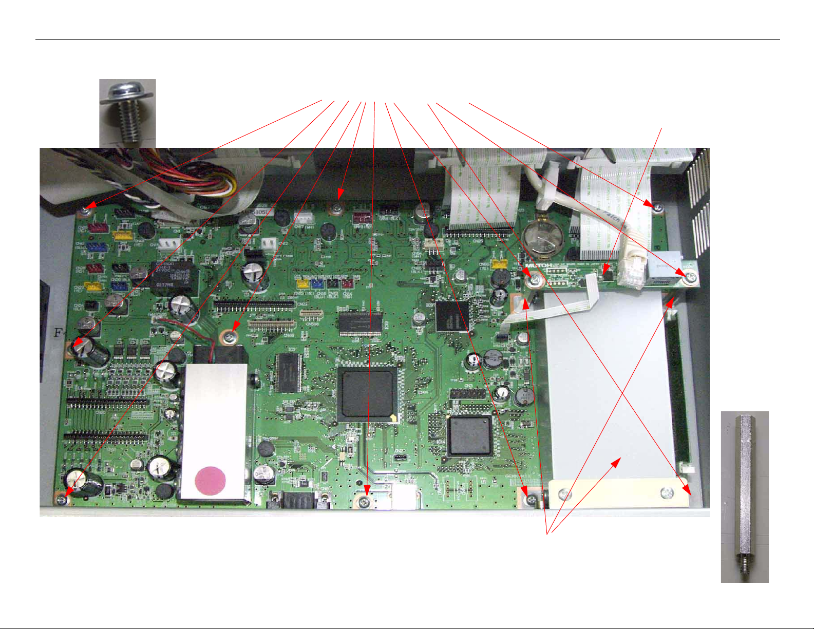
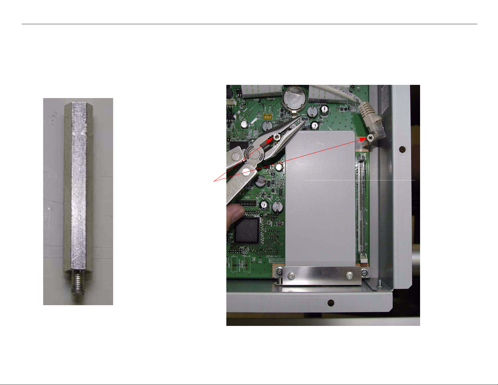
6. Remove 11 Screws and 2 Metal Support Rods and remove the LVDS Board.
1. Remove 11 Screws
2.Remove the LVDS Board
3.Use pliers to remove 2 Metal Support
Rods and remove the Ethernet Cover.
GS6000 Field Repair Guide 10/10/08
Board (Main) Removal Printer Component, Software Item, LCD Display, Printer Button Page 22.
7. Lift out the Main Board.
GS6000 Field Repair Guide 10/10/08
Board (Main) Removal Printer Component, Software Item, LCD Display, Printer Button Page 23.
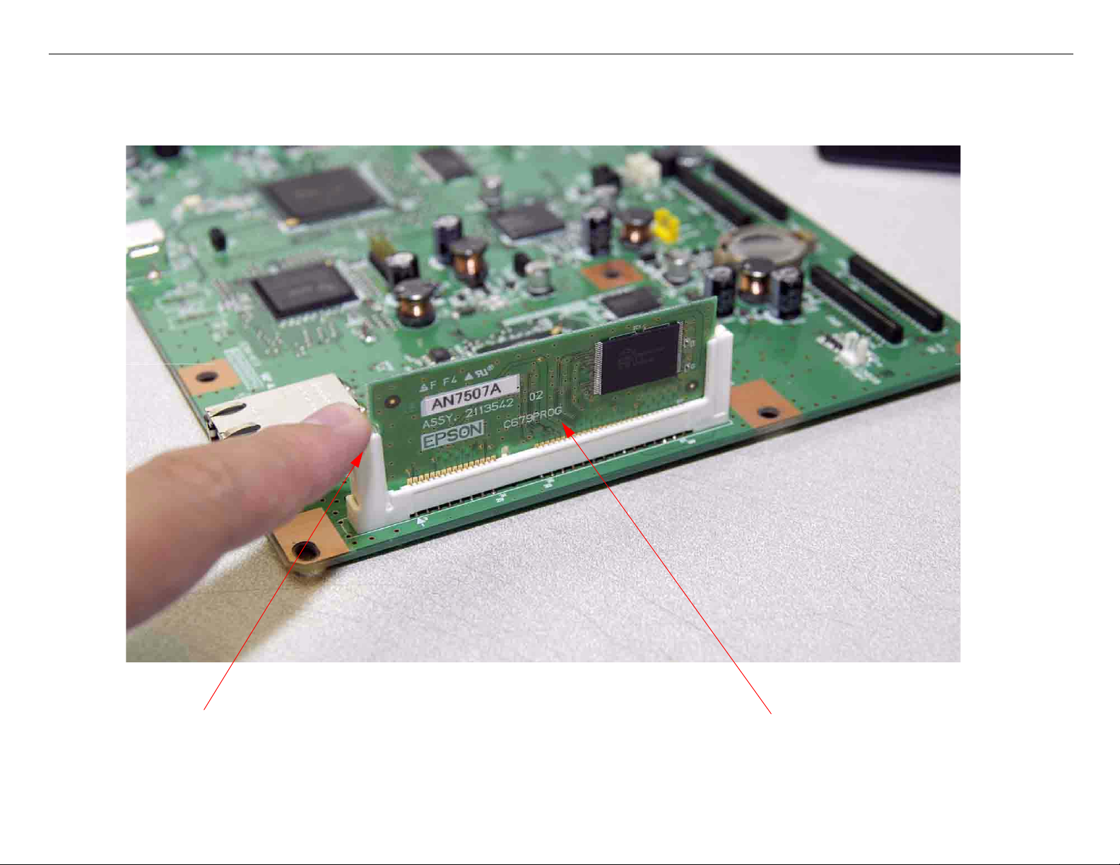
8. Remove the EDM SIMM from the Main Board.
1. Press here to release the EDM SIMM.
2. Lift out the EDM SIMM.

GS6000 Field Repair Guide 10/10/08
Board (Main) Installation Printer Component, Software Item, LCD Display, Printer Button Page 24.
Board (Main) Installation
Note: GS6000 Main Board Part # 2121641 (the part # is stamped on the board)
Main Board Installation (Overview)
• Install the EDM SIMM on the New Main Board
• Install the Main Board.
• Install the Ethernet Cover onto the Main Board.
• Install the Screws.
• Plug in the Cables.
• Close the Rear Cover.
• Upload Firmware.
• Install the Printer’s Parameters.
• Perform the RTC & USB ID Adjustment.
Main Board Installation (Detail)
1. Compare the New Main Board to the Old Main Board. Verify that the Components, Brackets,
and Part Numbers match.

GS6000 Field Repair Guide 10/10/08
Board (Main) Installation Printer Component, Software Item, LCD Display, Printer Button Page 25.
2. Install the EDM SIMM onto the Main Board.
Install the EDM SIMM.
GS6000 Field Repair Guide 10/10/08
Board (Main) Installation Printer Component, Software Item, LCD Display, Printer Button Page 26.
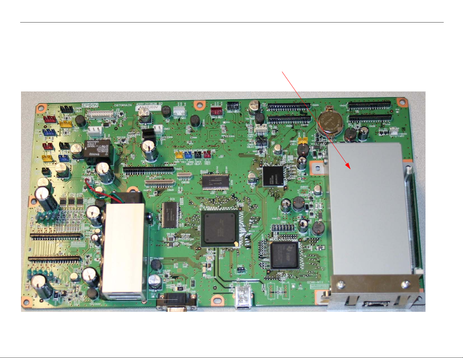
3. Install the Main Board into the Printer, and place the Ethernet Cover in position.
1. Drop in the Main Board.
2. Place the Ethernet Cover in position
GS6000 Field Repair Guide 10/10/08
Board (Main) Installation Printer Component, Software Item, LCD Display, Printer Button Page 27.
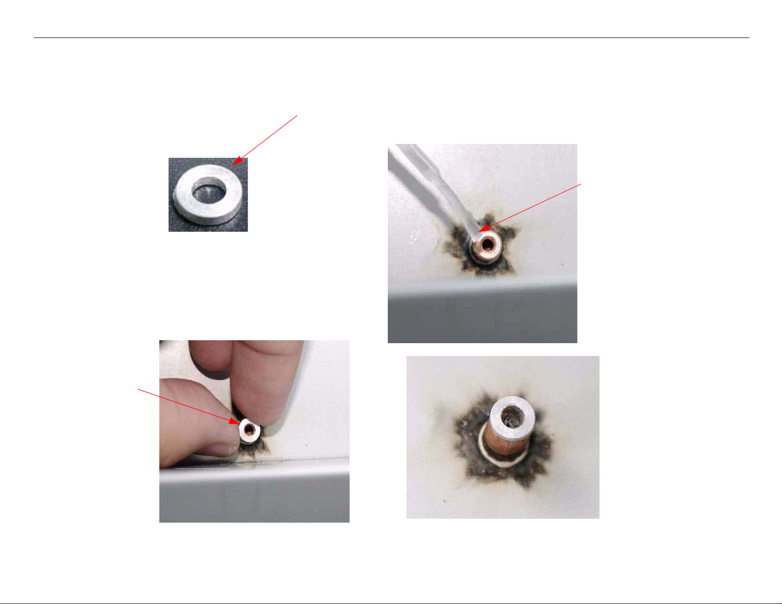
4. Make sure all screw stands have the washer on them.
During Mainboard removal or installation, this washer may come off it s screw
stand. Glue it back in place, making sure no glue leak into the thread of the
stand.
Brush a small amount of
glue on the outer edge of
the screw stand.
Install washer.
GS6000 Field Repair Guide 10/10/08
Board (Main) Installation Printer Component, Software Item, LCD Display, Printer Button Page 28.
5. Install 2 Metal Support Rod that fasten the Main Board and Ethernet Cover to the Printer.
Install 2 Metal Support
Rods, do not over-tighten.
GS6000 Field Repair Guide 10/10/08
Board (Main) Installation Printer Component, Software Item, LCD Display, Printer Button Page 29.
6. Install 11 screws that fasten the Main Board to the Printer.
Install 11 screws.
GS6000 Field Repair Guide 10/10/08
Board (Main) Installation Printer Component, Software Item, LCD Display, Printer Button Page 30.
7. Plug in 11 Wire cables
Plug in 11 Wire Cables
Loading...