


Instruction Manual Supplement |
L2, L2e, and L2sj Controller |
D103277X012 |
April 2013 |
|
|
Converting a Threaded NPT Connection to a Flange Connection
Supplement to Fisherr L2, L2e, and L2sj Level Controller Instruction Manuals
This supplement contains information for converting L2, L2e, and L2sj level controller threaded NPT connections to flange type connections.
Refer to the Maintenance section of the appropriate instruction manual for instructions on removing the sensor from the controller, and disassembly of the sensor connector.
See figures 1, 2, and 3 for conversion and weld end details.
Note
Modification of the L2, L2e, or L2sj sensor to a flanged connection limits the pressure rating to the flange rating. Refer to tables 1 and 3.
Ensure flanges are marked with the appropriate pressure rating.
Flange Orientation
Orient the controller so that the case is level. See figure 4 for the proper sensor orientation for flange welding.

 WARNING
To maintain code/standard compliance, weld fabrication must meet the requirements of ASME Section IX. Failures to meet these requirement could result in personal injury and/or property damage.

 WARNING
To maintain compliance with NACE MR0175, weld fabrication must meet the requirements of NACE MR0175, paragraph 5.3. Failure to meet these requirements could result in personal injury and/or property damage.
www.Fisher.com
L2, L2e, and L2sj Controller |
Instruction Manual Supplement |
April 2013 |
D103277X012 |
|
|
Figure 1. Typical Sensor Connection
CUT HERE TO
PREPARE |
|
|
FOR WELD |
|
BORE AND MACHINE TO |
|
||
10C2006-A |
|
GIVEN DIMENSIONS |
|
|
|
|
|
|
Figure 2. Sensor Connections (mm)
|
1.6 $0.4 |
|
1.6 $0.4 |
62.7 )2.3 *0.8 |
51.7 53.3 |
62.7 )2.3 *0.8 |
48.5 50.0 |
|
12.7 |
CONTROLLER |
12.7 |
|
CONTROLLER |
15.2 |
15.2 |
||
7.6 |
11.2 |
|||
|
|
|||
|
62 |
|
62 |
|
|
NPS 2 ANSI SCHED 40 |
|
NPS 2 ANSI SCHED 80 |
NOTE:
SEE FIGURE 1 FOR A TYPICAL SENSOR CONNECTION
62.7 )2.3 *0.8
CONTROLLER
1.6 $0.4
37.4 |
38.9 |
12.7
15.2
16.8
66.5
NPS 2 ANSI SCHED XXS
2

Instruction Manual Supplement |
L2, L2e, L2sj Controller |
D103277X012 |
April 2013 |
|
|
|
|
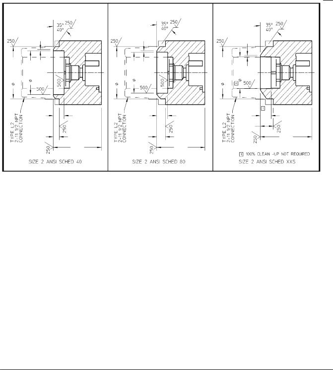
Figure 3. Sensor Connections (Inches) |
|
CONTROLLER |
CONTROLLER |
|
CONTROLLER |
|
NPS 2 ANSI SCHED 40 |
NPS 2 ANSI SCHED 80 |
NPS 2 ANSI SCHED XXS |
10C2006-A
NOTE:
SEE FIGURE 1 FOR A TYPICAL SENSOR CONNECTION
Figure 4. Sensor Orientation for Flange Mounting
FLANGE
45_ $2.5_
.06
A A
 1
1
|
RELATION |
|
|
SECTION A A |
|
WITH 4 HOLE FLANGE |
OF TABS TO THE |
WITH 8 HOLE FLANGE |
|||
BOLT PATTERN |
|||||
|
|
|
|
||
|
|
|
|
|
|
|
|
|
1 CONNECTION USED FOR ORIENTATION |
||
|
|
|
|
|
|
10C1996 A
3
 Loading...