


8510/8510B Valve |
Product Bulletin |
51.6:edisc (EMA) |
|
D100066X012 |
February 2013 |
|
|
Fisherr 8510 and 8510B Eccentric Disc Control
Valves (EMA)
Fisher 8510 and 8510B eccentric disc valves feature an eccentrically mounted disc and a PTFE or 316 stainless steel seal ring. The pressure-assisted seal ring provides excellent shutoff against pressure applied in either direction. The 8510B is a multi-class rated valve, available in NPS 2 through 12, and PN10 through PN100 compatible (compatibility varies with size and class, see table 1).
The 8510 is rated for CL150, available in NPS 14 through 24, and PN10 and PN16 compatible (compatibility varies with size and class, see table 1). These valves combine with a variety of power and manual actuators to form reliable, high-performance control valves suited for many liquid and gas applications requiring extremely low leakage. Constructions are available for temperatures up to 538 C (1000 F).
Unless otherwise noted, all NACE references are to NACE MR0175-2002.
Features
Sour Service Capability–Materials are available for applications involving sour service. These materials comply with the requirements of NACE MR0175-2002.
Excellent Flow Control–The eccentrically mounted disc design provides an approximately linear flow characteristic and can be used for on/off or throttling control applications through 90 degrees of disc rotation. Optional disc stop on 8510B provides seal protection.
(continued on page 3)
W4739-2
Eccentric Disc Control Valve with Fisher 1052 Actuator and 3610J Positioner
W9264-1
Fisher 8510B with Alternate Double D Shaft and 1035/El-O-Matic Actuator
www.Fisher.com

Product Bulletin |
8510/8510B Valve |
51.6:edisc (EMA) |
|
February 2013 |
D100066X012 |
|
|
Specifications |
|
Valve Sizes and End Connection Style
8510B: NPS J 2, J 4, J 6 and J 8 (PN10 through PN100) - CL150, 300 or 600 ASME flange compatibility, J 10 and J 12 (PN10 through PN40) - CL150 ASME flange compatibility
8510 flangeless valves: NPS J 14 (PN10 and PN16), J 16 (PN16), J 18, J 20 (PN16) and J 24 (PN16) - CL150 ASME flange compatibility for NPS 14 through 24
Also see table 1.
Maximum Inlet Pressures(1)
WCC Steel, CF3M Stainless Steel (316L SST), and CN7M (Alloy 20) Valve Bodies: Consistent with applicable pressure-temperature ratings in table 2, unless limited by pressure drop/temperature capabilities in tables 6, 7, 8, 9 and 10 or temperature capabilities in table 11
M35-1 Valve Bodies: As shown in table 2, unless further limited by pressure drop/temperature capabilities in table 10 or temperature capabilities in table 11
Maximum Pressure Drops(1)
Steel Valve Bodies (8510 and 8510B): See table 6 or 7 CF8M Stainless Steel Valve Bodies (8510): See tables 8 and 9
Alloy Valve Bodies (8510B): See table 10
Shutoff Classifications per ANSI/FCI 70-2 and IEC 60534-4
PTFE Seal Ring: Bidirectional shutoff to Class VI is standard
316 Stainless Steel Seal Ring: 0.001% of maximum valve capacity (one tenth of Class IV)
Construction Materials
See tables 3, 4, and 5
Material Temperature Capabilities(1)
See table 11
Flow Characteristic
Approximately linear
Flow Direction
Standard (forward flow) is with the seal retainer facing upstream; reverse flow is permissible within specified limitations
Flow Coefficients
See table 1
Flow Coefficient Ratio(2)
100 to 1
Noise Levels
See Catalog 12 for sound pressure level prediction
Disc Rotation
Clockwise to close (when viewed from actuator side of valve) through 90 degrees of disc rotation
Actuator Valve Action
With diaphragm or piston rotary actuator, field-reversible between J push-down-to-open (extending actuator rod opens valve) and J push-down-to-close (extending actuator rod closes valve)
With 1035 Rack and Pinion actuator with spring return or double acting action, field-reversible between J fail-to-open and J fail-to-close
Valve Classification
J Face-to-face dimensions of NPS 3 through 6 in CL150 and 300, and face-to-face dimensions of NPS 8 through 24 in CL150, meet API 609 standards for face-to-face dimensions of narrow flangeless and single-flange valves
J DIN face-to-face dimensions for all sizes meet DIN 3202 Part 3/K2, and
J JIS B2210 standard face-to-face dimensions are available on request.
Mating Flange Capabilities
All size compatible with welding-neck and slip-on flanges (schedule 80 or lighter for 8510B NPS 2 through 12; schedule 40 or lighter for 8510 NPS 14 through 24)
Shaft Diameters and Approximate Weights
See figures 7 and 8
Options
J Line flange bolting, J FGM line flange gaskets
1.The pressure/temperature limits in this bulletin and any applicable standard or code limitation should not be exceeded.
2.Ratio of maximum flow coefficient to minimum useable flow coefficient.
2

8510/8510B Valve |
Product Bulletin |
51.6:edisc (EMA) |
|
D100066X012 |
February 2013 |
|
|
ENVIRO-SEAL Packing System Specifications
Available Packing |
Construction Materials(3) |
||
J ENVIRO-SEAL PTFE Packing System |
PTFE Packing Systems: |
||
Packing Rings: PTFE V-ring(4) |
|||
J ENVIRO-SEAL Graphite Packing System |
|||
Male and Female Adaptor Rings: Carbon-filled PTFE |
|||
|
|
||
Maximum Temperature/Pressure Limits(1) |
V-ring |
||
Anti-Extrusion Rings: High strength polymer |
|||
|
|
||
Maximum Application Temperature/Pressure Limits |
Packing Box Rings: S31600 (316 SST) |
||
Graphite Packing Systems: |
|||
to meet EPA Fugitive Emission Standard of 100 |
|||
Packing Rings: Graphite |
|||
ppm(2): |
|||
For ENVIRO-SEAL PTFE Packing Systems: Up to 232 C |
Anti-Extrusion Rings: Carbon |
||
Packing Box Rings: S31600 (316 SST) |
|||
(450 F) at the ASME class rating of the valve. |
|||
Spring Pack Components: |
|||
For ENVIRO-SEAL Graphite Packing Systems: Up to |
|||
O-Ring: Nitrile. The O-ring serves as an assembly |
|||
316 C (600 F) at the ASME class rating of the valve |
|||
convenience to hold the springs in position on the |
|||
|
|
||
Material Temperature Range: |
follower. |
||
Packing Follower: S31600 with carbon-filled PTFE liner |
|||
|
|
||
For ENVIRO-SEAL PTFE Packing Material: |
Springs: N07718 |
||
-46 to 232 C (-50 to 450 F) |
Packing Flange: S31600 (316 SST) |
||
For ENVIRO-SEAL Graphite Packing Material: |
Packing Box Studs: Strain-hardened S31600, |
||
SA-193-B8M |
|||
Up to 316 C (600 F) |
Packing Box Nuts: S31600 SA-194-8M |
||
|
|
|
|
1.The pressure/temperature limits in this bulletin and any applicable standard or code limitation for valve should not be exceeded.
2.The Environmental Protection Agency (EPA) has set a limit of 100 parts per million (ppm) for fugitive emissions from a valve.
3.For other materials of construction, see table 3.
4.In vacuum service it is not necessary to reverse the ENVIRO-SEAL PTFE packing rings.
Features (continued)
Improved Environmental Capabilities–The optional ENVIRO-SEALt packing systems, shown in figure 6, are designed with very smooth stem surfaces, and live loading provides improved sealing, guiding, and loading force transmission. The seal of the ENVIRO-SEAL system can control emissions to below the EPA (Environmental Protection Agency) limit of 100 ppm (parts per million) for valves.
Lost Motion Minimized–For 8510, the taper pin/disc connection and the splined valve shaft with clamped lever and single pivot linkage reduce lost motion between the actuator and valve. For 8510B, the taper key/disc connection and the splined valve shaft with clamped lever and single pivot linkage reduce lost motion between the actuator and valve.
Greater Capacities and Lower Operating Torques–The contoured disc increases flow capacity and reduces operating torque at peak angles of disc opening.
3

Product Bulletin |
8510/8510B Valve |
51.6:edisc (EMA) |
|
February 2013 |
D100066X012 |
|
|
Construction Features
Field-Reversible Valve Action–The actuator/valve assembly action can be converted from push-down-to-open to push-down-to-close, or vice versa, without additional parts.
Integral Shaft-to-Body Bonding–Standard valve construction includes conductive packing to provide electrical bonding for hazardous area applications.
Easy Installation–Centering holes (figures 1, 2 and 3) engage the line flange bolts to simplify installation and provide for centering of the valve in the pipeline.
Long Seal Life–The opening and closing path of the eccentric disc (figure 4) minimizes disc contact with the seal ring, thereby reducing seal wear, undue friction, and seating torque requirements.
Exceptional Shutoff at High Pressure Drops–Both the 316 stainless steel seal ring and the bidirectional
PTFE seal ring with pressure-assisting sealing action (figure 5) are designed to provide shutoff regardless of flow direction.
Reliable Flange Gasketing Surface–The seal retainer cap screws or retention clips are outside the gasket surface of the seal retainer, and spiral wound or flat sheet gaskets can be installed between the uninterrupted seal retainer face and the pipeline flange.
Self-Flushing Action–With standard right-hand actuator mounting, the bottom edge of the disc opens downstream away from the seal, and the flow stream flushes sediment from the seal.
Double D Shaft–8510B valves in NPS 2 through 12 are available with double D shaft end designed to accept the 1035 Rack and Pinion Actuator and other quarter-turn actuators.
Shaft Retention–Redundant shaft protection is provided with 8510B valves with the double D drive shaft. The packing follower and stepped shaft interact to provide the redundant shaft retention.
4

8510/8510B Valve |
Product Bulletin |
51.6:edisc (EMA) |
|
D100066X012 |
February 2013 |
|
|
Figure 1. Typical Fisher 8510B Construction Detail
RETAINER CLIP
CENTERING HOLE |
VIEW A |
|
|
|
SEE VIEW A |
|
|
|
|
|
|
|
TAPER |
|
SEAL |
|
KEY |
|
|
|
|
RETAINER |
|
|
|
|
|
|
|
|
SEAL |
|
|
|
RING |
|
|
SEAL |
DISC |
|
|
|
|
|
|
RING |
|
|
|
ASSEMBLY |
SPRING |
BEARING |
|
|
|
|
|
VALVE |
|
SPACER |
|
|
|
|
|
BODY |
|
|
|
|
|
41B6064-A |
|
PTFE SEAL |
316 STAINLESS |
41B6101-A |
|
|
STEEL SEAL |
B2303* |
|
|
Figure 2. Typical Fisher 8510B Construction Detail with Double D Shaft
|
|
TAPER KEY |
|
|
REDUNDANT SHAFT |
CENTERING HOLE |
|
RETENTION DEVICE |
|
|
BEARING
SPACER
39b8285-A
E0781
5
Product Bulletin |
8510/8510B Valve |
51.6:edisc (EMA) |
|
February 2013 |
D100066X012 |
|
|
Figure 3. Construction of Fisher 8510
CENTERING
HOLE
48A5626-A
B1691-3
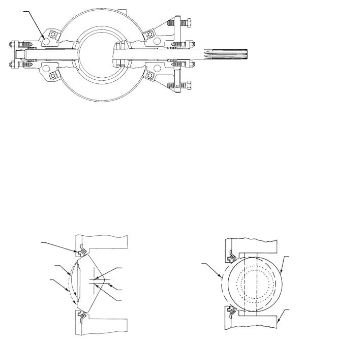
Figure 4. Comparison of Disc Action
SEAL RING (PTFE
CONSTRUCTION
SHOWN)
ECCENTRIC |
|
CONVENTIONAL |
ECCENTRIC |
|
DISK PATH |
|
|||
|
DISK |
DISK |
||
OF ROTATION |
ECCENTRIC |
|||
|
|
|||
|
|
|
||
CONVENTIONAL |
DISK CENTER |
|
|
|
DISK PATH |
OF ROTATION |
|
|
|
OF ROTATION |
CENTERLINE OF |
|
|
|
|
|
|
||
|
VALVE BODY |
|
|
|
|
CONVENTIONAL |
|
|
|
|
DISK CENTER |
|
VALVE BODY |
|
|
OF ROTATION |
|
||
|
|
|
SIDE VIEW – DISK FULLY CLOSED |
BOTTOM VIEW – DISK FULLY OPENED |
A2867-2 |
|
6
 Loading...