


1052 Actuator |
Product Bulletin |
61.1:1052 |
|
D104082X012 |
February 2015 |
|
|
Fisherr 1052 Size 70 Diaphragm Rotary
Actuator
Fisher 1052 size 70 spring return diaphragm rotary actuators operate splined shaft rotary valves, such as 8580, 8532, 8590, CV500, V500, and Vee Ballt (V150, V200 and V300) valves. 1052 actuators are suitable for on off service or for throttling service.
This actuator is designed for easy installation of a broad range of options: limit switches, position indicating switches, positioners, and manual over rides. Option applicability varies with actuator size. Refer to the specifications table and table 4 for information concerning option applicability and specifications.
Features
ν Application Flexibility-- 1052 rotary actuators are available with fail open or fail close construction and can be mounted in any of four actuator valve mounting positions. See figure 5 for mounting positions. These actuators can be mounted on a broad range of Fisher valves or used with other equipment.
ν Minimal Dead Band-- Single joint linkage with splined and clamped lever minimizes lost motion and improves control accuracy.
ν Long Service Life-- Rugged construction provides stability, corrosion resistance, and protection from deformation should over pressurization occur.
W8508-3
Typical Fisher 1052 Actuator with Vee Ball Valve and FIELDVUE™ DVC6200 Digital Valve Controller
ν Safety-- The 1052 actuator has an externally accessible spring adjuster to relieve spring compression (see figure 1). Actuator valve linkage is completely enclosed, yet the valve packing adjustment remains accessible without removing any parts (see figure 2).
www.Fisher.com

|
Product Bulletin |
1052 Actuator |
|
|
61.1:1052 |
|
|
|
February 2015 |
D104082X012 |
|
|
|
|
|
|
Specifications |
|
|
|
|
|
|
|
Available Configurations |
piping. If stroking time is critical, consult your |
|
|
For on off service without a positioner or for |
Emerson Process Management sales office |
|
|
|
|
|
|
throttling services with or without a positioner |
Diaphragm Casing Displacement |
|
|
Direct Acting: Increasing loading pressure extends |
|
|
|
the diaphragm rod out of the spring barrel |
See table 1 |
|
|
Actuator Sizes |
Construction Materials |
|
|
|
|
|
|
70 |
See table 3 |
|
|
|
|
|
|
Standard Diaphragm Pressure Ranges |
Material Temperature Capabilities(1) |
|
|
J 0 to 2.3 bar (0 to 33 psig), J 0 to 2.8 bar (0 to 40 |
|
|
|
Nitrile Diaphragm or O Rings(3): -40 to 82_C (-40 to |
|
|
|
psig), and J 0 to 3.8 bar (0 to 55 psig) |
|
|
|
180_F) |
|
|
|
|
|
|
|
Maximum Diaphragm Sizing Pressure(1) |
Silicone Diaphragm: -40 to 149_C (-40 to 300_F) |
|
|
3.8 bar (55 psig) |
Travel Indication |
|
|
|
|
|
|
Maximum Diaphragm Casing Pressure(5) |
Graduated scale and pointer combination located on |
|
|
4.5 bar (65 psig) |
actuator end of valve drive shaft |
|
|
Nominal Valve Shaft Rotation |
Pipe or Tubing Connection Sizes |
|
|
J 90 degrees (standard), J 60 degrees (optional), or |
Standard: 1/4 NPT internal |
|
|
J 75 degrees (optional) |
Optional: J 1/2 or J 3/4 NPT internal, |
|
|
|
|
|
|
Valve Shaft Diameters, mm (Inches) |
and J 3/4 NPT Pipe Away vent opening |
|
|
|
|
|
|
J 31.8 (1 1/4), J 38.1 (1 1/2), |
Mounting Positions |
|
|
J 44.5 (1 3/4), or J 50.8 (2) |
See figure 5 |
|
|
|
|
|
|
Maximum Breakout Torque(2) |
Approximate Weights |
|
|
Up to 1370 NSm (12,100 lbfSin) |
See table 2 |
|
|
Stroking Time |
Options |
|
|
Dependent on rotation, spring rate, initial spring |
Option applicability varies with actuator size. Refer to |
|
|
compression, supply pressure, and size of supply |
table 4 and the Options section. |
|
|
|
|
|
|
|
|
|
1.Use this value to determine the maximum torque output. The pressure/temperature limits in this bulletin and any applicable standard or code limitation for the actuator should not be exceeded.
2.Actual actuator torque available depends on specific construction and casing pressure. For information on torque requirements of the valve being considered, contact your Emerson Process Management sales office.
3.Nitrile O rings are used in the optional top mounted handwheel and in the optional up and down travel stop assemblies.
4.For higher temperature ratings, contact your Emerson Process Management sales office.
5.This maximum casing pressure is not to be used for normal operating pressure. Its purpose is to allow for typical regulator supply settings and/or relief valve tolerances.
Options
Top Mounted Handwheel: For infrequent use as a manual actuator or for use as an adjustable up travel stop (see figure 4). For repeated or daily manual operation, the unit should be equipped with a declutchable handwheel actuator.
Declutchable Handwheel Actuator: A side mounted manual actuator can be used to provide on site control and to provide override capabilities. See bulletin
61.8:1078 (D101339X012) for handwheel actuator specifications.
Limit Switches: Micro Switch or NAMCO switches for one or two single pole, double throw contacts. See separate bulletins for limit switch information.
Position Indicating Switch: TopWorx™ DXP M21GNEB switch for one through six single pole, double throw switch contacts are available. See separate bulletin for position indicating switch information.
2
1052 Actuator |
Product Bulletin |
61.1:1052 |
|
D104082X012 |
February 2015 |
|
|
Positioner: For precise positioning of the valve disk or ball, the actuator should be equipped with a positioner. Under some service conditions, the 1052 actuator may be used successfully in these applications without a positioner. For additional information, contact your Emerson Process Management sales office with complete service conditions.
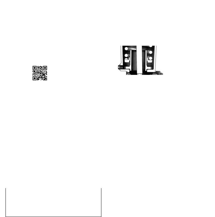
Figure 1. Sectional Views of Spring Seat Construction
Details
W4742-2crop
Adjustable Down Travel Stop: Used to limit the actuator stroke in the downward direction (see figure 3).
Adjustable Up Travel Stop: Used to limit the actuator stroke in the upward direction (see figure 3).
Actuator Locking Mechanism: An actuator locking mechanism is available. It can be used to keep the actuator in a locked position (the same as the spring fail position) during maintenance. The padlock is customer supplied, and the mechanism requires a modified actuator housing.
Pipe Away Vent: Some applications use natural gas or other hazardous gases as a supply pressure to the actuator. These applications sometimes require the actuator housing to be vented, reducing the accumulation of gases. For new constructions and retrofit kit information, contact your Emerson Process Management sales office with complete service conditions.
Table 1. Diaphragm Casing Displacement
|
CLEARANCE |
|
CASING VOLUME(2) |
|
|||
CASING |
60 Degree |
90 Degree |
|||||
VOLUME(1) |
|||||||
Rotation |
Rotation |
||||||
SIZE |
|
|
|||||
|
cm3 |
Inches3 |
cm3 |
Inches3 |
cm3 |
Inches3 |
|
70 |
3490 |
213 |
13,929 |
850 |
19,025 |
1161 |
|
|
|
|
|
|
|
|
|
1. Volume when the diaphragm is in the up position. 2. Includes clearance volume.
Table 2. Approximate Actuator Weights
|
1052 ACTUATOR |
TOP MOUNTED |
|||||
SIZE |
HANDWHEEL |
||||||
|
|
|
|||||
|
Kg |
Pounds |
|
Kg |
Pounds |
|
|
70 |
123 |
272 |
|
21.3 |
47 |
|
|
|
|
|
|
|
|
|
|
TYPICAL OF THE 1052
ACTUATOR WITH
ADJUSTABLE SPRING SEAT
Table 3. Construction Materials
PART |
MATERIAL |
|
Actuator |
||
Actuator Housing and Spring |
Cast iron |
|
Barrel |
||
|
||
|
|
|
Diaphragm |
Nitrile on nylon or silicone on |
|
polyester |
||
|
||
|
|
|
Diaphragm Head |
Cast Iron |
|
|
|
|
Diaphragm Casing(1) |
Pressed steel |
|
Diaphragm Rod |
Steel |
|
|
|
|
Housing Cover |
Cast iron or aluminum |
|
|
|
|
Lever |
Ductile iron |
|
|
|
|
Optional Top Mounted Handwheel Assembly |
||
Handwheel and Handwheel Body |
Cast iron |
|
|
|
|
Handwheel Stem |
Bronze |
|
|
|
|
O Rings |
Nitrile |
|
|
|
|
Pusher Plate |
Cast iron or steel |
|
|
|
|
Optional Down Travel Stop Assembly |
||
Closing Cap |
Brass |
|
|
|
|
O ring |
Nitrile |
|
|
|
|
Stem |
Stainless steel |
|
|
|
|
Travel Stop Body |
Cast iron |
|
|
|
|
Optional Up Travel Stop Assembly |
||
Closing Cap |
Brass |
|
|
|
|
O Ring |
Nitrile |
|
|
|
|
Stem |
Bronze |
|
|
|
|
Travel Stop Body |
Cast iron |
|
|
|
|
3
 Loading...