


Instruction Manual |
3710 and 3720 Positioners |
D101728X012 |
January 2015 |
|
|
Fisherr 3710 and 3720 Valve Positioners and
3722 Electro-Pneumatic Converter
Contents |
|
Introduction . . . . . . . . . . . . . . . . . . . . . . . . . . . . . . . . . |
2 |
Scope of Manual . . . . . . . . . . . . . . . . . . . . . . . . . . . . . |
2 |
Description . . . . . . . . . . . . . . . . . . . . . . . . . . . . . . . . . |
2 |
Positioner to Actuator Mountings List . . . . . . . |
5 |
Specifications . . . . . . . . . . . . . . . . . . . . . . . . . . . . . . . |
6 |
Educational Services . . . . . . . . . . . . . . . . . . . . . . . . . |
6 |
Installing the 3722 Converter . . . . . . . . . . . . . . . . . . . |
6 |
Hazardous Area Classifications and |
|
Special Instructions for “Safe Use” and |
|
Installation in Hazardous Areas |
|
for 3722 Converter . . . . . . . . . . . . . . . . . . . . . . . |
7 |
CSA . . . . . . . . . . . . . . . . . . . . . . . . . . . . . . . . . . . . |
7 |
FM . . . . . . . . . . . . . . . . . . . . . . . . . . . . . . . . . . . . . |
8 |
ATEX . . . . . . . . . . . . . . . . . . . . . . . . . . . . . . . . . . . |
8 |
IECEx . . . . . . . . . . . . . . . . . . . . . . . . . . . . . . . . . . |
10 |
Installation . . . . . . . . . . . . . . . . . . . . . . . . . . . . . . . . |
11 |
Mounting the Positioner . . . . . . . . . . . . . . . . . . . . . . |
11 |
Installing the 3710 or 3720 |
|
Pneumatic Positioner on Size 25 or 50 |
|
585 and 585R Actuators . . . . . . . . . . . . . . . . . . |
16 |
Connections . . . . . . . . . . . . . . . . . . . . . . . . . . . . . . . . |
18 |
Supply Connection . . . . . . . . . . . . . . . . . . . . . . . . . . |
19 |
Output Connections . . . . . . . . . . . . . . . . . . . . . . . . |
20 |
Instrument Connection . . . . . . . . . . . . . . . . . . . . . . |
20 |
Vent Opening, Purge Option, and Actuator |
|
Vent Connection . . . . . . . . . . . . . . . . . . . . . . . . . |
20 |
Connecting the Purge Tube . . . . . . . . . . . . . . . |
22 |
Electrical Connection for the 3720 |
|
Positioner . . . . . . . . . . . . . . . . . . . . . . . . . . . . . . . |
22 |
Diagnostic Connections . . . . . . . . . . . . . . . . . . . . . |
23 |
Calibration . . . . . . . . . . . . . . . . . . . . . . . . . . . . . . . . . . |
25 |
Setting the Initial Cam Position . . . . . . . . . . . . . . . |
25 |
Zero and Span Adjustments . . . . . . . . . . . . . . . . . . |
26 |
Standard or Beacon Indicator Alignment . . . . . . . . |
27 |
Changing Positioner Action . . . . . . . . . . . . . . . . . . . . |
28 |
Single Action/Double Action . . . . . . . . . . . . . . . . . |
29 |
Direct Action/Reverse Action . . . . . . . . . . . . . . . . . |
29 |
Split Range Operation . . . . . . . . . . . . . . . . . . . . . . . |
30 |
Changing the Spool Valve |
|
(To Increase Positioner Output Capacity) . . . . . |
30 |
Changing the Span Adjuster Assembly |
|
(To Change Positioner Input Range) . . . . . . . . . |
32 |
Principle of Operation . . . . . . . . . . . . . . . . . . . . . . . . |
33 |
Figure 1. Positioners
SUPPLY
CONNECTION
W6144
3720 POSITIONER MOUNTED ON A FISHER 1052 ACTUATOR
W6058 1
3710 POSITIONER MOUNTED ON A FISHER 1066 ACTUATOR
www.Fisher.com
3710 and 3720 Positioners |
Instruction Manual |
January 2015 |
D101728X012 |
|
|
Contents (cont'd)
Maintenance . . . . . . . . . . . . . . . . . . . . . . . . . . . . . . . . 34
Positioner Maintenance . . . . . . . . . . . . . . . . . . . . . . 34
Replacing the Standard or Beacon Indicator . 34
Removing the 3722 Converter . . . . . . . . . . . . 35
Removing the Positioner . . . . . . . . . . . . . . . . . 35
Removing the Feedback Arm Assembly . . . . . 36
Disassembling the Feedback Arm Assembly
and Span Adjuster Assembly . . . . . . . . . . . . 37
Removing the Feedback Shaft (Cam Shaft) . . 37
Disassembling the Spool Valve, Action Block,
and Gasket . . . . . . . . . . . . . . . . . . . . . . . . . . 37
Disassembling the Input Module and
Summing Beam Assembly . . . . . . . . . . . . . 38
Replacing the Input Module Diaphragm . . . . . 39
Assembling the Input Module and Summing
Beam Assembly . . . . . . . . . . . . . . . . . . . . . . 40
Assembling the Spool Valve, Action Block,
and Gasket . . . . . . . . . . . . . . . . . . . . . . . . . . 41
Assembling the Feedback Shaft
(Cam Shaft) . . . . . . . . . . . . . . . . . . . . . . . . . . 42
Replacing the Feedback Arm Assembly
and Span Adjuster Assembly . . . . . . . . . . . . 42 3722 Converter Maintenance . . . . . . . . . . . . . . . . . 42
Replacing the Converter Primary O Ring
and Filter . . . . . . . . . . . . . . . . . . . . . . . . . . . . 42 Disassembling the 3722 Converter . . . . . . . . . 43 Assembling the 3722 Converter . . . . . . . . . . . 43 Testing the 3722 Converter Module . . . . . . . . 44 Parts Ordering . . . . . . . . . . . . . . . . . . . . . . . . . . . . . . . 44 Parts Kits . . . . . . . . . . . . . . . . . . . . . . . . . . . . . . . . . . . 44 Parts List . . . . . . . . . . . . . . . . . . . . . . . . . . . . . . . . . . . 44 Positioner Common Parts . . . . . . . . . . . . . . . . . . . . . 44 Diagnostic Connections . . . . . . . . . . . . . . . . . . . . . . . 48 3722 Electro Pneumatic Converter . . . . . . . . . . . . . 49 Positioner Mounting Parts . . . . . . . . . . . . . . . . . . . . . 50
Mounting Parts for Mounting Positioner
Ãon 585 and 585R Actuators . . . . . . . . . . . . . . . . . . 54 Mounting Parts for the 67CFR on the
Ã1032 Actuator . . . . . . . . . . . . . . . . . . . . . . . . . . . . . 54 Fittings . . . . . . . . . . . . . . . . . . . . . . . . . . . . . . . . . . . . . 54 Loop Schematics . . . . . . . . . . . . . . . . . . . . . . . . . . . . . 54
Introduction
Scope of Manual
This instruction manual includes installation, operation, calibration, maintenance, and parts ordering information for the Fisher 3710 pneumatic positioner and 3720 electro pneumatic positioner.
This manual also provides field installation and maintenance information for the Fisher 3722 electro pneumatic converter. Refer to separate instruction manuals for information on the actuator, control valve, and other accessories.
Do not install, operate, or maintain a 3710 pneumatic positioner, a 3720 electro pneumatic positioner or a 3722 electro pneumatic converter without being fully trained and qualified in valve, actuator and accessory installation, operation and maintenance. To avoid personal injury or property damage it is important to carefully read, understand, and follow all of the contents of this manual, including all safety cautions and warnings. If you have any questions about these instructions, contact your Emerson Process Management sales office before proceeding.
Description
The 3710 pneumatic positioner and 3720 electro pneumatic positioner are used with either diaphragm actuators (spring return) or piston rotary actuators (spring return or double action) as shown in figure 1. These positioners provide a valve ball or disk position for a specific input signal. These positioners can easily be configured to provide single or double action output for rotary actuators.
The 3710 pneumatic positioner accepts a pneumatic input signal. The 3720 electro pneumatic positioner accepts a milliampere (mA), direct current (DC), input signal. Refer to table 1 for an explanation of type numbers.
The 3710 pneumatic positioner provides a valve position for a standard pneumatic input signal. The positioner may also be split ranged. See table 3 for input signal ranges.
The 3720 electro pneumatic positioner provides a valve position for a milliampere (mA), direct current (DC), input signal. The positioner may also be split ranged. See table 3.
2

Instruction Manual |
3710 and 3720 Positioners |
D101728X012 |
January 2015 |
|
|
Table 1. Specifications
Available Configurations
3710: J Single or J double acting pneumatic rotary valve positioner
3720: J Single or J double acting electro pneumatic rotary valve positioner consisting of a 3710 with a 3722 attached 3722: An electro pneumatic converter that converts a 4-20 mA DC input signal to a 0.2 to 1.0 bar (3 to 15 psig) signal for the pneumatic positioner
Input Signal
3710:
Standard: J 0.2 to 1.0 bar (3 to 15 psig)or J 0.4 to 2.0 bar (6 to 30 psig)
Split Range: J 0.2 to 0.6 bar (3 to 9 psig) and 0.6 to 1.0 bar (9 to 15 psig) or J 0.4 to 1.2 bar (6 to 18 psig) and 1.2 to 2.0 bar (18 to 30 psig)
3720:
Standard: J 4-20 mA DC constant current with 30 VDC maximum compliance voltage Split Range: J 4-12 mA DC or 12-20 mA DC
Equivalent Circuit
3720: 120 ohms shunted by three 5.6 V zener diodes. See figure 15.
Output Signal
Pneumatic pressure as required by the actuator up to full supply pressure
Action(1): Field reversible between J direct and J reverse within the pneumatic positioner
Supply Pressure(2)
Recommended: 0.3 bar (5 psig) above actuator requirement
Maximum: 10.3 bar (150 psig) or maximum pressure rating of the actuator, whichever is lower
Supply Medium
3710: air or natural gas(3)
3720: air
3720 positioners are not approved for use with natural gas as the supply medium
Steady State Air Consumption(4)
3710:
6 mm Standard Spool Valve: 0.82 normal m3/hr (29 scfh) at 4.1 bar (60 psig) supply pressure
3720:
6 mm Spool Valve: 1.0 normal m3/hr (36 scfh) at 4.1 bar (60 psig) supply pressure
Maximum Supply Air Demand(4) (Double Acting
Output)
6 mm Spool Valve: 20 normal m3/hr (700 scfh) at 4.1 bar (60 psig) supply pressure
Typical Performance(5)
3710:
Independent Linearity: ±0.5% of output span
Hysteresis: 0.5% of output span Deadband: 0.3% of input span
3720:
Independent Linearity: ±1.0% of output span
Hysteresis: 0.6% of output span Deadband: 0.35% of input span
Electromagnetic Compatibility for 3722 electro pneumatic converter
Meets EN 61326 1 (First Edition) ÃImmunity—Industrial locations per Table 2 of ÃÃthe EN 61326 1 standard. Performance is ÃÃshown in table 2 below. ÃEmissions—Class A
ÃÃISM equipment rating: Group 1, Class A
Note: Electromagnetic Interference (EMI) specifications also apply to 3720 positioners
Operating Influences
Supply Pressure Sensitivity: A 10% change in supply pressure changes the valve shaft position less than the following percentages of valve rotation:
3710: 1.0% at 4.1 bar (60 psig) supply pressure 3720: 1.5% at 4.1 bar (60 psig) supply pressure
Operative Temperature Limits(2)
J -40 to 80_C (-40 to 180_F), J -50 to 107_C (-58 to 225_F)
continued
3

3710 and 3720 Positioners |
Instruction Manual |
January 2015 |
D101728X012 |
|
|
Table 1. Specifications (Continued)
Hazardous Area Classification for 3710 Positioner
3710 pneumatic positioners comply with the requirements of ATEX Group II Category 2 Gas and Dust
Electrical Classifications for 3722 Converter
CSA— Intrinsically Safe, Explosion-proof, Type n, Dust Ignition-proof
FM— Intrinsically Safe, Explosion-proof, Type n, Dust Ignition-proof, Non incendive
ATEX— Intrinsically Safe, Flameproof, Type n IECEx— Intrinsically Safe, Flameproof, Type n
Refer to Hazardous Area Classifications and Special Instructions for “Safe Use” and Installation in Hazardous Locations, starting on page 7, for additional information.
Note: These classifications also apply to the 3720 positioner
Housing Classification for 3722 Converter
CSA— Type 3 Encl.
FM— NEMA 3, IP54
ATEX— IP64
IECEx— IP54
Mount instrument with vent on side or bottom if weatherproofing is a concern.
Note: These classifications also apply to the 3720 positioner
Other Classifications/Certifications for 3722 Converter
INMETRO— National Institute of Metrology, Quality and Technology (Brazil)
KGS— Korea Gas Safety Corporation (South Korea)
Contact your Emerson Process Management sales office for classification/certification specific information
Pressure Connections
1/4 NPT internal
Electrical Connection for 3720 Positioner
1/2 14 NPT conduit connection
Rotary Valve Rotation
J 90 degrees (standard) J 60 degrees (optional)
Approximate Weight
3710: 2.04 kg (4.5 pounds) 3720: 2.72 kg (6.0 pounds)
Declaration of SEP
Fisher Controls International LLC declares this product to be in compliance with Article 3 paragraph 3 of the Pressure Equipment Directive (PED) 97 / 23 / EC. It was designed and manufactured in accordance with Sound Engineering Practice (SEP) and cannot bear the CE marking related to PED compliance.
However, the product may bear the CE marking to indicate compliance with other applicable European Community Directives.
NOTE: Specialized instrument terms are defined in ANSI/ISA Standard 51.1 Process Instrument Terminology.
1.For direct action, an increasing input signal extends actuator rod. For reverse action, an increasing input signal retracts actuator rod.
2.The pressure and temperature limits in this document, and any applicable code or standard limitation should not be exceeded.
3.Natural gas should not contain more than 20 ppm of H2S.
4.Normal cubic meters per hour (0°C and 1.01325 bar absolute). Scfh — standard cubic feet per hour (60°F and 14.7 psia).
5.Typical values tested using a 1061 size 30 actuator at 4.1 bar (60 psig) supply pressure. Performance may vary with other actuator types and supply pressures.
Table 2. Fisher 3722 Electro Converter(1) EMC Summary Results—Immunity
Port |
Phenomenon |
Basic Standard |
Test Level |
Performance |
|
Criteria(2) |
|
||||
|
|
|
|
|
|
|
Electrostatic Discharge (ESD) |
IEC 61000 4 2 |
4 kV contact |
A |
|
|
8 kV air |
||||
|
|
|
|
|
|
|
|
|
|
|
|
|
|
|
80 to 1000 MHz @ 10V/m with 1 kHz AM at 80% |
|
|
Enclosure |
Radiated EM field |
IEC 61000 4 3 |
14000 to 2000 MHz @ 3V/m with 1 kHz AM at 80% |
A |
|
|
|
|
2000 to 2700 MHz @ 1V/m with 1 kHz AM at 80% |
|
|
|
|
|
|
|
|
|
Rated power frequency magnetic |
IEC 61000 4 8 |
60 A/m at 50 Hz |
A |
|
|
field |
||||
|
|
|
|
|
|
|
|
|
|
|
|
|
Burst (fast transients) |
IEC 61000 4 4 |
1 kV |
A |
|
|
|
|
|
|
|
I/O signal/control |
Surge |
IEC 61000 4 5 |
1 kV (line to ground only, each) |
B |
|
|
Conducted RF |
IEC 61000 4 6 |
150 kHz to 80 MHz at 3 Vrms |
A |
|
|
|
|
|
|
|
Specification limit = ±1% of span
1. The information contained in this table also applies to the 3720 positioner.
2. A = No degradation during testing. B = Temporary degradation during testing, but is self recovering.
4
Instruction Manual |
|
3710 and 3720 Positioners |
|
D101728X012 |
|
January 2015 |
|
|
|
|
|
Table 3. Input Signal Range |
|
|
|
|
|
|
|
POSITIONER |
INPUT SIGNAL RANGE |
||
Pneumatic |
Electronic |
||
|
|||
3710 |
J 0.2 to 1.0 bar (3 to 15 psig) |
|
|
w/3 to 15 psig span adj. ass'y |
J 0.2 to 0.6 bar (3 to 9 psig) and |
––– |
|
(no color coding) |
0.6 to 1.0 bar (9 to 15 psig), split ranging |
|
|
|
|
|
|
3710 |
J 0.4 to 2.0 bar (6 to 30 psig) |
|
|
w/6 to 30 psig span adj. ass'y |
J 0.4 to 1.2 bar (6 to 18 psig) and |
––– |
|
(red color coding) |
1.2 to 2.0 bar (18 to 30 psig), split ranging |
|
|
|
|
|
|
3720 |
––– |
J 4-20 mA DC |
|
J 4-12 mA DC or 12-20 mA DC, split ranging |
|||
|
|
||
|
|
|
|
Positioner to Actuator Mountings List
The positioner mounts directly to the actuator cover plate of Fisher 1051, 1052, and 1061 actuators. See table 4 for actuator sizes.
Figure 2 shows a positioner ready for mounting on a piston rotary actuator. A mounting plate (key 43) is used to mount the positioner base plate to Fisher 1031, 1032, 1051, 1052, 1061, 1066, and 2052 actuators. See table 4 for actuator sizes.
The positioner also mounts on a Fisher 585 and 585R size 25 or 50 sliding stem actuator. A mounting plate (key 43) is used to mount the positioner base plate to the actuator.
Figure 2. Mounting the Positioner Base Plate
MOUNTING
SCREW 
FEEDBACK |
|
|
|
SHAFT |
|
|
|
|
TIE BAR |
POSITIONER |
|
MOUNTING SCREWS |
MOUNTING |
||
EXTENSION (KEY 44) |
|||
W6059 1 |
PLATE (KEY 43) |
||
|
5

3710 and 3720 Positioners |
Instruction Manual |
January 2015 |
D101728X012 |
|
|
Table 4. Positioner to Actuator Mountings
|
POSITIONER TO ACTUATOR MOUNTINGS |
|
Direct Mounting to Actuator Cover Plate(1) |
|
Mounting Plate Required |
S1051, size 30(2), 40, and 60 |
|
S1031, size 26, 33, 45, 60, and 80 |
|
S1032, size 45, 70, 185, 280, 425, 680, 1125, 1370, 2585, and 4580 |
|
S1052, sizes 30(2), 40, 60, and 70 |
|
|
|
|
|
S1061, size 30, 40, 60, and 68 |
|
S1051, size 33 |
|
S1052, size 20, 33 |
|
|
|
|
|
|
S1061, size 80, 100 |
|
|
S1066, size 20, 27, and 75 |
|
|
S2052, size 1, 2, and 3 |
|
|
|
1. Includes purge tube option. |
|
|
2. The size 30 actuator is no longer manufactured by Emerson Process Management. 3710 and 3720 positioners are available for field installation on existing size 30 actuators. |
||
|
|
|
Specifications
Specifications are shown in table 1.
Educational Services
For information on available courses for 3710 pneumatic positioners or 3720 electro pneumatics positioners, as well as a variety of other products, contact:
Emerson Process Management Educational Services, Registration
Phone: +1-641-754-3771 or +1-800-338-8158 e mail: education@emerson.com http://www.emersonprocess.com/education
Installing the 3722 Converter
See figure 3.

 WARNING
Avoid personal injury from sudden release of process pressure. Before mounting the 3720 electro pneumatic positioner or 3722 electro pneumatic converter:
D Wear protective eyewear, gloves and clothing whenever possible.
D Do not remove the actuator from the valve while the valve is still pressurized.
D Disconnect any operating lines providing air pressure, electric power, or a control signal to the actuator. Be sure the actuator cannot suddenly open or close the valve.
D Use bypass valves or completely shut off the process to isolate the valve from process pressure. Relieve process pressure on both sides of the valve.
D Relieve any supply or output pressure in the existing positioner.
D When installing an electro pneumatic positioner or converter in a hazardous area, turn off control signals until installation is complete. Be sure all safety barriers, connections, and the converter housing cap and O ring are properly installed before supply a control signal to the unit.
6

Instruction Manual |
3710 and 3720 Positioners |
D101728X012 |
January 2015 |
|
|
D Use lock out procedures to be sure that the above measures stay in effect while you work on the equipment.
D Do not open where an explosive dust atmosphere is present.
D Check with your process or safety engineer for any additional measures that must be taken to protect against process media.

 WARNING
The positioner can provide full supply pressure to any connected equipment. To avoid personal injury and equipment damage, make sure supply pressure never exceeds the maximum safe working pressure of any connected equipment.
Hazardous Area Classifications and Special Instructions for “Safe Use” and Installation in Hazardous Locations for 3722 Converter
Note
These Special Instruction for “Safe Use” and Installation in Hazardous Location also apply to 3720 positioners.
Certain nameplates may carry more than one approval, and each approval may have unique installation/wiring requirements and/or conditions of “safe use”. These special instructions for “safe use” are in addition to, and may override, the standard installation procedures. Special instructions are listed by approval.
Note
This information supplements the nameplate markings affixed to the product.
Always refer to the nameplate itself to identify the appropriate certification. Contact your Emerson Process Management sales office for approval/certification information not listed here.

 WARNING
Failure to follow these conditions of “safe use” could result in personal injury or property damage from fire or explosion, and area re classification.
CSA
Intrinsically Safe, Explosion-proof, Type n, Dust Ignition-proof
No special conditions for safe use.
Refer to table 5 for approval information.
7

3710 and 3720 Positioners |
Instruction Manual |
January 2015 |
D101728X012 |
|
|
Table 5. Hazardous Area Classifications for Fisher 3722 Converter(1)—CSA (Canada)
Certification Body |
Certification Obtained |
Entity Rating |
Temperature Code |
|
Intrinsically Safe |
Vmax = 30 VDC |
T4 (Tamb ≤ 82°C) |
|
Ex ia IIC T4/T5/T6 per drawing GE28591 (figure 34) |
Imax = 150 mA |
|
|
Ex ia Intrinsically Safe |
Pi = 1.25 W |
T5 (Tamb ≤ 62°C) |
|
Class I, II Division 1 GP A,B,C,D,E,F,G T4/T5/T6 |
Ci = 0 nF |
T6 (Tamb ≤ 47°C) |
|
per drawing GE28591 (figure 34) |
Li = 0 mH |
|
|
|
|
|
|
Explosion-proof |
|
T5 (Tamb ≤ 82°C) |
CSA |
Ex d IIC T5 |
- - - |
|
Class I, Division 1, GP A,B,C,D T5 |
|
|
|
|
|
|
|
|
|
|
|
|
Type n |
- - - |
T6 (Tamb ≤ 82°C) |
|
Ex nA IIC T6 |
||
|
|
|
|
|
|
|
|
|
Class I, Division 2, GP A,B,C,D T6 |
|
T6 (Tamb ≤ 82°C) |
|
|
|
|
|
Class II, Division 1, GP E,F,G T5 |
- - - |
T5 (Tamb ≤ 82°C) |
|
|
|
|
|
Class II, Division 2, GP F,G T6 |
|
T6 (Tamb ≤ 82°C) |
|
|
|
|
1. These hazardous area classification also apply to 3720 positioners.
FM
Intrinsically Safe, Explosion-proof, Type n, Dust Ignition-proof, Non incendive
No special conditions for safe use.
Refer to table 6 for approval information.
Table 6. Hazardous Area Classifications for Fisher 3722 Converter(1)—FM (United States)
Certification Body |
Certification Obtained |
Entity Rating |
Temperature Code |
|
Intrinsically Safe |
Vmax = 30 VDC |
T4 (Tamb ≤ 82°C) |
|
Imax = 150 mA |
||
|
Class I Zone 0 AEx ia IIC T4/T5/T6 per drawing GE28590 (figure 35) |
||
|
Pi = 1.25 W |
T5 (Tamb ≤ 62°C) |
|
|
Class I, II, III Division 1 GP A,B,C,D,E,F,G T4/T5/T6 |
||
|
Ci = 0 nF |
T6 (Tamb ≤ 47°C) |
|
|
per drawing GE28590 (figure 35) |
||
|
Li = 0 mH |
|
|
|
|
|
|
|
|
|
|
|
Explosion-proof |
|
T5 (Tamb ≤ 82°C) |
FM |
Class I Zone 1 AEx d IIC T5 |
- - - |
|
Class I, Division I, GP A,B,C,D T5 |
|
|
|
|
|
|
|
|
|
|
|
|
Type n |
- - - |
T5 (Tamb ≤ 82°C) |
|
Class I Zone 2 AEx nA IIC T5 |
||
|
|
|
|
|
|
|
|
|
Class I, Division 2, GP A,B,C,D T5 |
|
|
|
Class II, Division 1, GP E,F,G T5 |
- - - |
T5 (Tamb ≤ 82°C) |
|
Class II, Division 2, GP F,G T5 |
|
|
|
|
|
|
1. These hazardous area classification also apply to 3720 positioners. |
|
|
|
|
|
|
|
ATEX
Standards Used for Certification
EN 60079-0: 2012 |
EN 60079-31: 2009 |
EN 60079-1: 2007 |
EN 61241-0: 2006 |
EN 60079-11: 2012 |
EN 61241-1: 2004 |
EN 60079-15: 2010 |
EN 61241-11: 2006 |
8

Instruction Manual |
3710 and 3720 Positioners |
D101728X012 |
January 2015 |
|
|
Special Conditions for Safe Use
Intrinsically Safe
This equipment is intrinsically safe and can be used in potentially explosive atmospheres.
The electrical parameters of certified equipment which can be connected to the device must not exceed one of these following values: U0 ≤ 30 VDC; I0 ≤ 150 mA; P0 ≤ 1.25 W
Ambient temperature: T6, at Tamb = 47_C ; T5, at Tamb = 62_C ; T4, at Tamb = 82_C
Flameproof
The flame path is other than required by EN 60079 1. Contact the manufacturer for information on the dimensions of the flameproof joints.
Electrical connections are typically made using either cable or conduit.
D If using a cable connection, the cable entry device shall be certified in type of explosion protection flameproof enclosure “d”, suitable for the conditions of use and correctly installed.
For ambient temperatures over 70_C, cables and cable glands suitable for at least 90_C shall be used.
D If using a rigid conduit connection, an Ex d certified sealing device such as a conduit seal with setting compound shall be provided immediately to the entrance of the enclosure.
For ambient temperatures over 70_C, the wiring and setting compound in the conduit seal shall be suitable for at least 90_C.
Type n
No special conditions for safe use.
Refer to table 7 for approval information.
Table 7. Hazardous Area Classifications for Fisher 3722 Converter(1)—ATEX
Certification |
Certification Obtained |
Entity Rating |
Temperature Code |
|
II 1 G & D |
|
|
|
|
|
|
|
Intrinsically Safe |
Ui = 30 VDC |
T4 (Tamb ≤ 82°C) |
|
Gas |
T5 (Tamb ≤ 62°C) |
|
|
Ex ia IIC T4/T5/T6 Ga |
Ii = 150 mA |
T6 (Tamb ≤ 47°C) |
|
|
Pi = 1.25 W |
|
|
Dust |
|
|
|
Ci = 0 nF |
|
|
|
Ex ia IIIC Da T120 °C (Tamb ≤ 82°C)/T100 °C |
- - - |
|
|
Li = 0 mH |
||
|
(Tamb ≤ 62°C) / T85 °C (Tamb ≤ 47°C) |
|
|
|
|
|
|
|
|
|
|
|
II 2 G & D |
|
|
|
|
|
|
|
Flameproof |
|
T5 (Tamb ≤ 82°C) |
ATEX |
Gas |
|
|
|
Ex d IIC T5 Gb |
- - - |
|
|
Dust |
|
- - - |
|
Ex tb IIIC T82 °C Db (Tamb ≤ 79°C) |
|
|
|
|
|
|
|
|
|
|
|
II 3 G & D |
|
|
|
|
|
|
|
Type n |
|
T6 (Tamb ≤ 82°C) |
|
Gas |
|
|
|
Ex nA IIC T6 Gc |
- - - |
|
|
Dust |
|
- - - |
|
Ex tc IIIC Dc T85 °C (Tamb ≤ 82°C) |
|
|
|
|
|
|
|
|
|
|
1. These hazardous area classification also apply to 3720 positioners. |
|
|
|
9

3710 and 3720 Positioners |
Instruction Manual |
January 2015 |
D101728X012 |
|
|
IECEx
Conditions of Certification
Intrinsically Safe

 WARNING
Substitution of components may impair intrinsic safety.
-40_C ≤ Ta ≤ +82_C; T6 (Ta ≤ +47_C); T5 (Ta ≤ +62_C); T4 (Ta ≤ +82_C) Entity Parameters: Ui = 30 V, li = 150 mA, Pi = 1.25 W, Ci = 0 nF, Li = 0 mH
Flameproof

 WARNING
Disconnect power before opening.
-40_C ≤ Ta ≤ +82_C; T5 (Ta ≤ +82_C)
Type n

 WARNING
Disconnect power before opening.
-40_C ≤ Ta ≤ +82_C; T6 (Ta ≤ +82_C)
Refer to table 8 for approval information.
Table 8. Hazardous Area Classifications for Fisher 3722 Converter(1)—IECEx
Certification |
Certification Obtained |
Entity Rating |
Temperature Code |
|
|
|
Ui = 30 VDC |
T4 (Tamb ≤ 82°C) |
|
|
Intrinsically Safe |
Ii = 150 mA |
||
|
Gas |
Pi = 1.25 W |
T5 (Tamb ≤ 62°C) |
|
|
Ex ia IIC T4/T5/T6 Ga |
Ci = 0 nF |
T6 (Tamb ≤ 47°C) |
|
|
|
Li = 0 mH |
|
|
IECEx |
|
|
|
|
Flameproof |
|
T5 (Tamb ≤ 82°C) |
||
|
Gas |
- - - |
||
|
Ex d IIC T5 Gb |
|
|
|
|
|
|
|
|
|
Type n |
|
T6 (Tamb ≤ 82°C) |
|
|
Gas |
- - - |
||
|
Ex nA IIC T6 Gc |
|
|
|
1. These hazardous area classification also apply to 3720 positioners.
10
Instruction Manual |
3710 and 3720 Positioners |
D101728X012 |
January 2015 |
|
|
Installation
To change an existing 3710 positioner into a 3720 positioner, install a 3722 electro pneumatic converter (figure 3). The 3722 electro pneumatic converter mounts over the input and supply connections of the 3710 positioner.
Figure 3. Fisher 3722 Electro Pneumatic Converter
 SUPPLY CONNECTION
EXTERNAL GROUNDING
SCREW
1/2 NPT CONDUIT CONNECTION
W6145
1.Be sure all safety procedures have been followed. Remove the input and supply connections from the existing 3710 base plate and clean the ports.
2.Locate the two O rings (key 85, figure 32) and properly lubricate (key 82) them. Place one O ring in the recessed area surrounding the input port on the positioner base plate. Place the other O ring around the supply port.
3.Locate the two socket head mounting screws (key 84). Properly orient the converter and secure it to the positioner base plate with the mounting screws. Be sure the O rings remain in place while securing the converter to the positioner base plate.
4.Connect supply pressure to the converter supply port.
Mounting the Positioner
Typically, a positioner is ordered with an actuator. At the factory, the positioner is mounted on the actuator and calibrated. However, a positioner can be ordered separately and mounted on an existing actuator.
To field mount a positioner to an existing actuator, an actuator cover plate with mounting holes and purge tube knockout may be required. Check the existing actuator cover plate. It must have three positioner mounting holes and, for specific actuators, a purge tube knockout. See table 4.
11

3710 and 3720 Positioners |
Instruction Manual |
January 2015 |
D101728X012 |
|
|
If the proper mounting holes are present, perform the following mounting procedure and then follow the calibration procedures in this instruction manual. Refer to the appropriate instruction manuals for actuator and valve mounting procedures.

 WARNING
Avoid personal injury from sudden release of process pressure. Before mounting the 3720 electro pneumatic positioner or 3722 electro pneumatic converter:
D Wear protective eyewear, gloves and clothing whenever possible.
D Do not remove the actuator from the valve while the valve is still pressurized.
D Disconnect any operating lines providing air pressure, electric power, or a control signal to the actuator. Be sure the actuator cannot suddenly open or close the valve.
D Use bypass valves or completely shut off the process to isolate the valve from process pressure. Relieve process pressure on both sides of the valve.
D Vent the power actuator loading pressure and relieve any actuator spring precompression.
D Use lock out procedures to be sure that the above measures stay in effect while you work on the equipment.
D When installing a positioner or converter in a hazardous area, turn off control signals until installation is complete. Be sure all safety barriers, connections, and the converter housing cap and O ring are properly installed before supplying a control signal to the unit.
D Check with your process or safety engineer for any additional measures that must be taken to protect against process media.

 WARNING
The positioner can provide full supply pressure to any connected equipment. To avoid personal injury and equipment damage, make sure supply pressure never exceeds the maximum safe working pressure of any connected equipment.
Note
The positioner mounts directly to the actuator cover plate of several Fisher actuators. See table 4. To directly mount the positioner to an existing Fisher actuator, you must use an actuator cover plate with three positioner mounting holes and the 5/8 inch purge option knockout plug.
See the parts list for the specific actuator cover plate required above to integrally mount the positioner.
See figures 4 and 33 for positioner mounting drawings.
Note
To mount the positioner to an actuator with an existing Fisher 3610 positioner, remove the 3610 positioner and replace it with an appropriate metal cover plate and four cap screws. For assistance, contact your Emerson Process Management sales office.
12

Instruction Manual |
3710 and 3720 Positioners |
D101728X012 |
January 2015 |
|
|
Figure 4. Typical Positioner/Actuator Combinations
42B8466 A
3710 POSITIONER MOUNTED ON A
1061 SIZE 30 ACTUATOR
42B8466 A
3720 POSITIONER MOUNTED ON A
1061 SIZE 30 ACTUATOR
NOTES:
FIGURE 33 SHOWS ADDITIONAL POSITIONER/ACTUATOR COMBINATIONS
1  ACTUATOR COVER PLATE REQUIRED WHEN REPLACING AN INSTALLED 3610 POSITIONER
13

3710 and 3720 Positioners |
Instruction Manual |
January 2015 |
D101728X012 |
|
|
1.See figure 5 for a typical actuator. Remove the actuator travel indicator machine screws, travel indicator, and actuator cover cap screws.
Note
When removing the actuator cover plate, take care not to change the position of the rod end bearing on the end of the turnbuckle inside the actuator housing.
2.If necessary, install a new cover plate.
a.Remove the existing cap screws and actuator cover plate from the actuator housing.
b.Remove the retaining ring (e clip) and hub from the cover plate.
c.Install the hub and retaining ring into the new actuator/positioner cover plate.
Note
Position the actuator cover plate so the positioner mounting holes on the new cover plate allow placement of the positioner in the desired orientation.
Actuator cover alignment on the 1052 actuator can be aided by moving the actuator slightly away from its “up” travel stop using a regulated air source. If the hole alignment cannot be obtained in this manner, temporarily loosen the cap screws that secure the housing to the mounting yoke and shift the housing slightly. Do not completely travel the actuator while the cover is removed.
Tighten the actuator cap screws before continuing.
3.Position the new actuator/positioner cover plate so the positioner mounting holes on the new cover plate allow placement of the new positioner in the desired orientation. Secure the new cover plate to the actuator.
4.Install the positioner tie bar (key 42) in place of the travel indicator on the actuator hub.
Note
Before installation of the positioner mounting plate (key 43), review the mounting drawings (figures 4 and 33). Properly align the positioner mounting plate before attaching the mounting plate to the actuator cover plate. Note that the three positioner mounting holes must be aligned to match the three mounting screws which will pass through the base of the positioner.
5.If the specific actuator requires a positioner mounting plate (key 43), install the mounting plate using the cap screws (key 45).
6.Unscrew the four captive cover screws and remove the cover assembly (key 7) from the positioner.
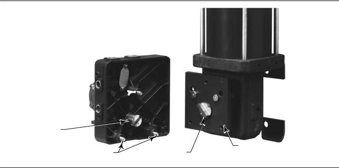
7.See figure 6. Loosen the cam locknut (key 37) and rotate the feedback shaft (key 38) as necessary to align the slot in the feedback shaft end with the tie bar on the actuator hub. Tighten the cam locknut.
8.Align the positioner with the mounting holes in the new actuator cover plate or positioner mounting plate. Be sure that the tie bar fits securely into the feedback shaft end slot. Secure the positioner to the actuator cover plate or mounting plate using the (hex) socket head cap screws (key 46).
9.Before installing the positioner cover, properly align the valve position indicator (standard, low profile indicator or optional beacon indicator). Follow the standard or beacon indicator alignment procedure given in this instruction manual. Then, install the positioner cover assembly.
14
Instruction Manual |
3710 and 3720 Positioners |
D101728X012 |
January 2015 |
|
|
Figure 5. Typical Piston Actuator (Fisher 1061)
W6146 1
W6147 1
TIE BAR, MOUNTING PLATE REMOVED REAR VIEW, POSITIONER BASE PLATE, AND MOUNTING AREA
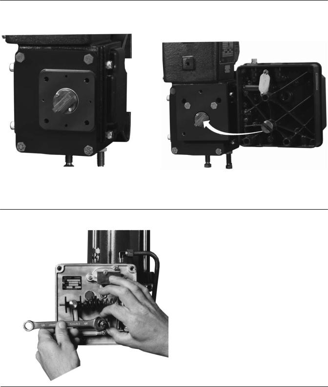
Figure 6. Loosening the Cam Locknut
W5916
15
3710 and 3720 Positioners |
Instruction Manual |
January 2015 |
D101728X012 |
|
|
Installing the 3710 or 3720 Pneumatic Positioner on Size 25 or 50 585 and 585R Actuators
Refer to figures 7, 8, and 9 for key number locations unless noted otherwise.
Figure 7. Typical Fisher 3710 Positioner Mounted on a 585 Actuator
|
SPACER |
|
CAP SCREW |
(KEY 61) |
|
|
|
|
(KEY 99) |
|
MOUNTING PLATE |
|
|
|
LOCK WASHER |
|
(KEY 43) |
|
|
|
(KEY 100) |
|
DRIVE STUD BRACKET |
|
|
|
|
|
(KEY 98) |
|
|
CAP SCREW |
HEX NUT |
|
(KEY 93) |
|
|
|
(KEY 96) |
|
MOUNTING BEARING |
|
|
|
|
|
(KEY 97) |
|
|
CAP SCREW |
|
|
(KEY 46) |
|
LOCK |
CAP SCREW |
|
WASHER |
|
|
KEY 45 |
|
|
(KEY 92) |
|
|
|
|
|
|
|
1.An actuator stem bracket is supplied with the positioner. Assemble the various positioner feedback parts to the stem bracket as follows:
a.Refer to figure 8. Install the roller bearing (key 101) on the drive stud (key 95) and secure with the E ring (key 102).
b.Refer to figure 9. Attach the drive stud (with roller bearing) to the drive stud bracket (key 98) with 1/4 inch hex nut (key 96), lock washer (key 100), and flat washer (key 103). Place the flat washer between the lock washer and the hex nut. The washers and hex nut should all be on the same side of the drive stud bracket as shown in figure 9. The flat washer may be moved to the other side of the drive stud (between the drive stud and the drive stud bracket) if extra space is required to position the roller bearing near the center of the feedback lever. Leave the hex nut loose for later adjustment.
c.Attach the drive stud bracket (with drive stud) to the actuator stem bracket using two cap screws (key 99), two lock washers (key 100), and two hex nuts (key 96). Leave the hex nuts loose for later adjustment.
2.Stroke the actuator from the top stop to the bottom stop, and record the travel.
In steps 3 through 6, refer to the actuator instruction manual for key number locations unless noted otherwise.
3.Loosen eight screws, and remove the front and back yoke covers (keys 18 and 20).
4.Loosen the two cap screws in the stem connector assembly (key 15) and remove the stem connector. Separate the actuator piston stem (key 12) from the valve plug stem.
16

Instruction Manual |
3710 and 3720 Positioners |
D101728X012 |
January 2015 |
|
|
Figure 8. Drive Stud and Roller Bearing Assembly
|
ROLLER BEARING |
DRIVE STUD |
(KEY 101) |
E RING |
|
(KEY 95) |
(KEY 102) |
Figure 9. Drive Stud Bracket with Drive Stud and Roller Bearing Assembly
|
DRIVE STUD BRACKET |
|
(KEY 98) |
|
LOCK |
|
WASHER |
|
(KEY 100) |
FLAT WASHER |
DRIVE STUD |
(KEY 1103) |
AND ROLLER BEARING |
HEX NUT (KEY 96)
Note
Before performing the next step, position the valve plug stem at the lower end of its travel. Position the actuator stem at the upper travel stop. Check for sufficient clearance between the actuator stem and the valve stem to allow removing the stem bracket assembly. If there is insufficient clearance, remove the actuator from the valve.
5.Loosen the stem bracket retainer (key 14) and let it slide down over the valve plug stem. Remove the stem bracket assembly (key 13).
6.Install the stem bracket assembly (with drive stud and drive stud bracket) on the actuator stem. Align the stem bracket assembly so that it will be parallel with the back yoke cover. Install the stem bracket retainer and tighten to 68 NSm (50 lbfSft). If the actuator was removed from the valve, install the actuator on the valve. Do not attach the stem connector at this time.
7.Attach the mounting bearing (key 97) to the mounting plate (key 43) with three hex socket cap screws (key 93).
8.Refer to the actuator instruction manual. Loosen the four screws, and remove the actuator blanking plate.
9.Attach the positioner mounting plate to the actuator yoke as shown in figure 10 with four spacers (keys 61), four cap screws (key 45) and lock washers (key 92).
10.Loosen the four captive cover screws and remove the positioner cover.
11.Loosen the cam locknut (key 37, figure 31).
12.Attach the positioner to the mounting plate with three hex socket cap screws (key 46). Make sure that the positioner feedback shaft (key 38, figure 31) rotates freely and is not binding with the mounting bearing, adjust if necessary.
13.Attach the feedback lever (key 94) to the end of the feedback shaft with the two hex socket cap screws (key 93). The markings on the feedback lever should be visible when looking toward the back of the positioner. Make sure the roller bearing (key 101) on the drive stud engages the slot in the feedback lever.

 WARNING
An unexpected change in actuator supply pressure while performing the following steps could result in personal injury. Use lockout procedures to ensure a stable air supply.
14.Perform the Actuator Mounting procedure steps 2 through 8 in the actuator instruction manual to reconnect the actuator stem and valve stem.
17
 Loading...