


Fisher 657

www.Fisher.com
Fisherr 657 and 667 Diaphragm Actuators
Fisher 657 and 667 spring-opposed diaphragm
actuators position the valve plug in the valve in
response to varying controller or valve positioner
pneumatic output signals applied to the actuator
diaphragm. Zero setting of the actuator is determined
by the compression of the actuator spring. Span is set
by both the actuator spring rate and the number of
springs available. The 657 actuator is direct-acting; the
667 is reverse-acting. These actuators are designed to
provide dependable on-off or throttling operation of
automatic control valves.
Features
Application Versatility–Five actuator types in eleven
sizes are available for an extensive variety of
applications. Spring rates, travel stops, and manual
operators are available for nearly any control valve
application.
Excellent Linearity Between Loading Pressure and
Travel–A molded diaphragm travels in a deep
diaphragm casing, minimizing area change
throughout the travel.
High Degree of Dynamic Stability and Frequency
Response–A shallow casing on the pressure side
means reduced volume on that side, thereby
minimizing response time.
High Thrust Capability–The molded diaphragm
allows maximum thrust for given diaphragm size.
Long Service Life–Rugged thick-walled cast iron and
steel construction provides increased stability,
corrosion protection, and protection from
deformation should over-pressurization occur.
657 ACTUATOR
667 ACTUATOR
W2174-2 W1916-3
Fisher 657 and 667 Actuators Mountedon
easy-et Valves
Cold Service Applications–Enhanced product
specifications for all sizes of 657 and 667 diaphragm
actuators allow performance to -50_C(-58_F). Use
of a positioner is recommended to ensure
responsiveness in applications operating below
-40_C(-40_F).
Positive Connections–A split block stem connection
provides a solid transfer of motion while allowing
easy mounting. The absence of linkages helps to
avoid lost motion and inaccurate valve positioning.
657 and 667 Actuators
D100087X012
Product Bulletin
61.1:657
May 2012

657 and 667 Actuators
D100087X012
Product Bulletin
61.1:657
May 2012
2
Specifications
Standard Operating Pressure Range
(1)
657 and 667: J 0.2to1.0bar(3to15psig)orJ 0.4
to 2.0 bar (6 to 30 psig)
657-4 and 667-4: 0.2to1.9bar(3to27psig)
667 Size 76:
J 0.4to2.0bar(6to30psig)orJ 0to
3.1 bar (0 to 45 psig)
Maximum Travel
See table 1
Output Indication
Stainless steel disk or pointer and graduated scale
Stroking Speed
Dependent on actuator size, travel, spring rate, initial
spring compression, and supply pressure. If stroking
speed is critical, consult your Emerson Process
Management sales office
Maximum Allowable Thrust
(2)
See table 1
Operating Temperature Range
(1)
Standard Construction (Nitrile Elastomers): -40 to
82_C(-40to180_F)
Optional Construction (Silicone Diaphragm):
-40 to
149
C(-40to300F)
Maximum Valve Packing Box Temperature: 427_C
(800_F) with cast iron yoke
Volumetric Displacement
See table 2
Signal Connections
Sizes 30 - 60 and 667 Size 76: 1/4 NPT internal
Sizes 70 and 87: 1/2 NPT internal
Size 80
657: 3/4 NPT internal with 1/4 NPT internal bushing
667: 1/2 NPT internal with 1/4 NPT internal bushing
Size 100: 1 NPT internal with 1/4 NPT internal bushing
Effective Diaphragm Area
See table 1
Construction Materials (refer to figure 1)
Diaphragm Casing
Sizes 30
-
87: Steel
Size 80:
J Cast iron or J steel
Size 100:
J Cast aluminum
Diaphragm
Sizes 30
-
87: J Nitrile on nylon, J Silicone on
polyester
Size 100: Nitrile on polyester
Diaphragm Plate
657 Sizes 30
-
60, 100: J Cast aluminum
657 Sizes 70
-
87: J Cast iron or J steel
667 Sizes 30
-
60, 100: J Cast aluminum or J steel
667 Sizes 70
-
87: J Cast iron or J steel
Actuator Spring: Steel
Spring Adjustor: Steel
Spring Seat:
J Steel or J cast iron
Actuator Stem: Steel
Travel Indicator: Stainless steel
O-Rings: Nitrile
Seal Bushing: Brass
Stem Connector: Zinc-plated steel
Yoke
Sizes 30
-
80: J Cast iron or J steel
Size 100: Steel
Construction Materials for Cold Service
[to -50_C(-58_F)] 657 and 667--all sizes
Yoke: Steel (Grade LCC)
Diaphragm: Silicone
O-Rings:
(3)
Ethylene Propylene
Bolting: Stainless Steel B8M Cl 2
Stem Connector: Stainless Steel
Lubricant: Silicone
Stem and Yoke Boss Diameters
See table 1
Approximate Weight
See table 3
Options
J Oversize signal connections, J Plastic yoke covers,
J Watertight yoke (sealed construction for certain
applications where valve stem and packing must be
protected)
1. The pressure and temperature limits in this bulletin and in any applicable standard o r code limitation shouldnot be exceeded.
2. Do not exceed thethrust limits in thisbulletin.
3. Includes diaphragmcasing seals, casing-mounted handwheel on 657, seal bushingon 667.

657 and 667 Actuators
D100087X012
Product Bulletin
61.1:657
May 2012
3
Available Configurations
Direct Action
All 657 actuators are direct acting. Applying air
pressure to the upper diaphragm casing forces the
actuator stem downward. When this pressure is
reduced, the opposing spring force moves the
actuator stem upward. Should the loading pressure
fail, the spring forces the stem to the extreme upward
position. This provides fail-open action for
push-down-to-close valves and fail-closed action for
push-down-to-open valves.
657–Adirect- acting actuator used on sliding-stem
valves. Available in sizes 30 through 100. See figures 1,
2, 5, and 6.
657-4–A 657 actuator in sizes 70 and 87, designed
with 102 mm (4-inch) travel.
Reverse Action
All 667 actuators are reverse acting. Applying air
pressure to the lower diaphragm casing forces the
actuator stem upward against the opposing spring
force. When this loading pressure is reduced, the
spring moves the actuator stem downward. Should
the loading pressure fail, the spring forces the stem to
the extreme downward position. These actuators
provide fail-closed action for push-down-to-close
valves and fail-open action for push-down-to-open
valves.
667–A reverse-acting actuator used on sliding-stem
valves. Available in sizes 30 through 100 and 76. See
figures1,2,and7.
667-4–A 667 actuator in sizes 70 and 87, designed
with 102 mm (4-inch) travel.
Accessories
Handwheels
Handwheels for diaphragm actuators are often used as
adjustable travel stops. They also provide a ready
means of positioning the control valve in an
emergency. The specifications in tables 5 and 6 apply
to handwheels on both 657 and 667 Series actuators.
For repeated or daily manual operation, the unit
should be equipped with a side-mounted handwheel
actuator.
Top-Mounted Handwheels–Typical 657 and 667
actuators with handwheels mounted on the
diaphragm case are shown in figure 2 (not available on
a 667 actuator, size 80). On the 657 actuator, the
handwheel can be set to limit the travel in the upward
direction; on the 667 actuator, travel in the downward
direction can be restricted. A P-2 travel stop (figure 4)
is available for a 667 actuator, sizes 45-60 to limit
travel in either the upward ordownwarddirections.An
actuator with a P-2 travel stop is limited to a maximum
travel of 19 mm (0.75 inch). The handwheel on the size
100 is similar in function to those on the smaller sizes,
but it uses a gear drive similar to the drive employed
on the integral side-mounted handwheels (see figure
2).
Contents
Features 1.....................................
Specifications 2................................
Available Configurations 3.......................
Direct Action 3.................................
Reverse Action 3...............................
Accessories 3..................................
Handwheels 3.................................
Adjustable Travel Stops 7........................
Other 7.......................................
Ordering Information 14.........................
Tables
Additional Specifications 5.......................
Volumetric Casing Displacement 6................
Approximate Actuator Weights
(without handwheel) 6........................
Thrust Capabilities 7............................
Handwheel Specifications 10.....................
Adjustable Travel Stop Styles 11..................
Dimensions 14.................................
657 and 667 Actuators
D100087X012
Product Bulletin
61.1:657
May 2012
4
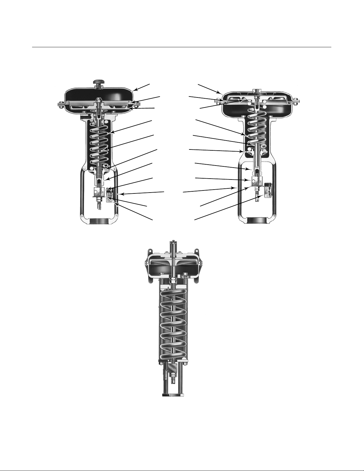
Figure 1. Typical Actuators
W0364-2
W0363-2
DIAPHRAGM CASINGS
667 SIZES 30-87
657 SIZES 30-87
W0366-1
657 SIZE 100
DIAPHRAGM
DIAPHRAGM PLATE
ACTUATOR SPRING
ACTUATOR STEM
SPRING SEAT
SPRING ADJUSTOR
STEM CONNECTOR
YOKE
TRAVEL INDICATOR DISK
INDICATOR SCALE

657 and 667 Actuators
D100087X012
Product Bulletin
61.1:657
May 2012
5
Table 1. Additional Specifications for Fisher 657 and 667 Series Actuators
ACTUATOR
SIZE
EFFECTIVE
DIAPHRAGM
AREA
YOKE
BOSS
DIAMETER
STEM
DIA
MAXIMUM
TRAVEL
MAXIMUM
ALLOWABLE
THRUST
(1)
cm
2
mm N
30 297 54 9.5 19 10,231
34 445 54 9.5 29 10,231
40 445 71 12.7 38 12,010
45 677 71 12.7 51 25,132
46 1006 71 12.7 51 33,584
50 677 90 19.1 51 25,131
60 1006 90 19.1 51 30,246
70
(2)
1419 90 19.1
76
39,142
102
(3)
76(667) 1006 90 19.1 51 30,246
80 1761 127
25.4
76
63,392
31.8 88,075
(4)
87
(2)
1419 127 25.4
76
39,142
102
(3)
100 2902
127H
(5)
31.8
102 200,160
178 50.8
Inch
2
Inch Lb
30 46 2-1/8 3/8 0.75 2300
34 69 2-1/8 3/8 1.125 2300
40 69 2-13/16 1/2 1.5 2700
45 105 2-13/16 1/2 2 5650
46 156 2-13/16 1/2 2 7550
50 105 3-9/16 3/4 2 5650
60 156 3-9/16 3/4 2 6800
70
(2)
220 3-9/16 3/4
3
8800
4
(3)
76(667) 156 3-9/16 3/4 2 6800
80 273 5
1
3
14,150
1-1/4 19,800
(4)
87
(2)
220 5 1
3
8800
4
(3)
100 450
5H
(5)
1-1/4
4 45,000
7 2
1. These values are based on material limitations such as yoke, stem connection, diaphragm plate, and travel stop strengths.
2. Values also apply to657-4 and 667-4 actuators.
3. For 657-4 and 667-4actuator constructions.
4. Steel construction.
5. H=Heavy actuator-to-valve bolting.
 Loading...