Emerson H200 Data Sheet

Bulletin 71.4:H200
December 2009
H200 Series Relief Valves
W1929–1
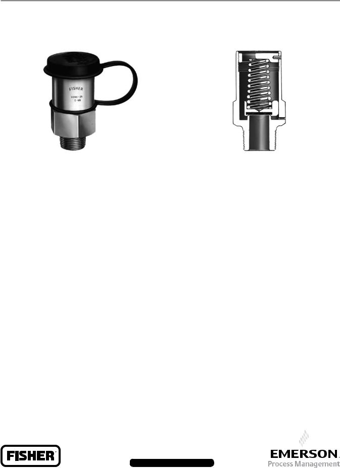
Figure 1. External View of H200 Series Relief Valve
Introduction
The H200 Series Pop™ relief valves, Figures 1 and 2, are self-operated relief valves with preset and pinned spring retainers. The inlet pressure registers directly on a spring-opposed poppet assembly which includes a Nitrile (NBR) disk. When the inlet gas pressure increases above the spring setting, the poppet and disk assembly is pushed away from the orifice. Springs are available that provide any relief pressure setting from 25 to 300 psig (1,7 to 20,7 bar).
With this simple operation and wide spring setting selection, the H200 Series Pop relief valves may be used where venting to atmosphere is acceptable, where the process gas is compatible with the Nitrile (NBR) disk, where its relief capacity is adequate, and where some pressure relieving tolerance is acceptable. Common applications include use on pneumatic control lines of air drills, jackhammers and other similar equipment, and on
farm tap installations. The H200 Series is comprised of the Types H202 and H203 relief valves with the difference being in the inlet connection size.
W0120–1
Figure 2. Sectional View of H200 Series Relief Valve
Features
• Space-Saving Construction - Small relief valve size allows installation where space is limited.
• Economical - Low initial cost, easy installation, and high capacity per dollar invested reduces total cost of having relief valve capabilities in your system.
• Durable - Brass body construction and stainless steel spring reduces susceptibility to corrosion damage and the preset, pinned spring retainer prevents relief valve setpoint tampering.
Installation
This relief valve may be installed in any position but must be oriented so that gas discharged from the valve does not create a fire, toxic, or explosion hazard.
The relief valve should be protected from material and conditions that could clog the outlet side of the valve and affect the venting of gas.
A typical installation is shown in Figure 3. A Type P145 raincap is recommended for use with any H200 Series relief valve. Dimensions are shown in Figure 4.
The relief valve and installation should be checked for compliance with all applicable codes.
D100165X012
www.fisherregulators.com

Bulletin 71.4:H200
Specifications
Available Configurations and End Connections
Type H202: 3/4 NPT connection
Type H203: 1 NPT connection
Maximum Allowable Relief (Inlet) Pressure(1)
400 psig (27,6 bar)
Relief Pressure Ranges(1)
See Tables 1 and 2
Flow Capacity
See Table 2
Representative Wide-Open Sizing Coefficient
Cg: 405
Construction Materials
Body, Poppet, and Spring Retainer: Brass
Disk: Nitrile (NBR)
Spring: 302 Stainless Steel
Temperature Capabilities(1)
-20° to 160°F (-29° to 71°C)
Approximate Weight
0.5 pounds (0,2 kg)
Option
Type P145 raincap
1. The pressure/temperature limits in this Bulletin or any applicable code limitations should not be exceeded.
Table 1. Relief Pressure Spring Ranges
RELIEF PRESSURE SETTINGS |
SPRING |
SPRINg |
RELIEF SETTING TOLERANCE |
|||
Psig |
bar |
PART NUMBER |
COLOR |
Psig |
bar |
|
25 to 30 |
1,7 to 2,1 |
1H485637022 |
Pink |
±5 |
±0,34 |
|
31 to 55 |
2,1 to 3,8 |
1J152137022 |
White |
|||
|
|
|||||
56 to 75 |
3,9 to 5,2 |
1P391137022 |
Blue |
|
|
|
65 to 95 |
4,5 to 6,5 |
T1049037022 |
Plain |
±8 |
±0,55 |
|
90 to 130 |
6,2 to 9,0 |
1F791337022 |
Purple |
|
|
|
131 to 160 |
9,0 to 11,0 |
1F7912T0012 |
Yellow |
|
|
|
161 to 190 |
11,1 to 13,1 |
T12699T0012 |
Green |
±15 |
±1,03 |
|
191 to 235 |
13,2 to 16,2 |
1F790937022 |
Brown |
|||
|
|
|||||
236 to 300 |
16,3 to 20,7 |
1E954637052 |
Plain |
|
|
|
|
|
|
|
|
|
|
Table 2. Relief Set Pressures and Capacities
|
RELIEF SET |
SET PRESSURE |
|
|
|
|
||
|
PRESSURE(2) |
PLUS BUILD-UP |
|
|
3 |
(1) |
||
|
|
|
|
|
|
FLOW CAPACITY, SCFH (Nm |
/h) |
|
Psig |
|
bar |
Psig |
|
bar |
|
|
|
25 |
|
1,7 |
50 |
|
3,4 |
34 200 |
(916) |
|
50 |
|
3,4 |
75 |
|
5,2 |
47 400 (1270) |
|
|
75 |
|
5,2 |
100 |
|
6,9 |
60 000 (1608) |
|
|
100 |
|
6,9 |
120 |
|
8,3 |
69 600 (1865) |
|
|
125 |
|
8,6 |
150 |
|
10,3 |
83 400 (2235) |
|
|
150 |
|
10,3 |
180 |
|
12,4 |
100 500 |
(2693) |
|
175 |
|
12,1 |
210 |
|
14,5 |
117 600 (3152) |
|
|
200 |
|
13,8 |
240 |
|
16,5 |
132 000 |
(3538) |
|
225 |
|
15,5 |
270 |
|
18,6 |
150 000 |
(4020) |
|
250 |
|
17,2 |
300 |
|
20,7 |
165 000 |
(4422) |
|
|
|
|
|
|
|
|
|
|
275 |
|
19,0 |
330 |
|
22,7 |
180 000 |
(4824) |
|
300 |
|
20,7 |
360 |
|
24,8 |
195 000 |
(5226) |
|
1. This is the initial leak point, the point at which the relief valve begins to discharge.
2. 0.6 Specific Gravity Gas. To convert to equivalent capacities of other gases, multiply the table values by 0.775 for air or 0.789 for nitrogen. Multiply the flow obtained by 0.0268 to convert to (Nm3/h) at 0°C and 1,01 bar.
Ordering Information
When ordering an H200 Series relief valve, specify the type number and the relief pressure setting required.
2
 Loading...