


Fisher 4195K
www.Fisher.com
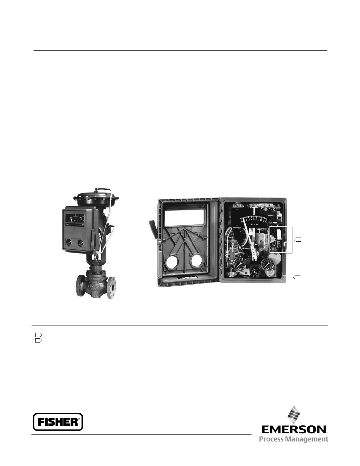
Fisherr 4195K Gauge Pressure Indicating
Controllers
Fisher 4195K gauge pressure indicating controllers
show process pressure and set point on an
easy‐to‐read process scale. The controllers compare
process pressure with an operator‐adjusted set point
and delivers a pneumatic signal to a control element so
that process pressure changes toward the set point.
Controller types are available for proportional‐only,
proportional‐plus‐reset, proportional‐plus‐reset‐
plus‐rate, and differential gap for on‐off control. 4195K
controllers are used in industries where accurate
pressure control and process monitoring are required.
Unless otherwise noted, all NACE references are to
NACE MR0175-2002.
YOKE‐MOUNTED CONTROLLER
INTERIOR OF A FISHER 4195KBME CONTROLLER
Notes:
1 An internal cover protects the proportional band adjustment mechanism. In this photograph, the cover has been removed.
2 Controller components are indicated in figure 1.
1
2
W5660‐1
W5663‐1
4195K Pressure Controllers
D200050X012
Product Bulletin
34.5:4195K
July 2014

4195K Pressure Controllers
D200050X012
Product Bulletin
34.5:4195K
July 2014
2
Specifications
Available Configurations
See table 1
Process Sensor Range (Input Signal)
Lower and Upper Range Limits:
As shown in tables 2 and 5
Maximum Allowable Pressure:
As shown in tables 2 and 5
Process Scale
Standard scale is matched to the range of the sensing
element, with exception of receiver controllers.
Optional scales available
(1)
.
Process Connections
Standard: 1/4 NPT internal stainless steel (all input
ranges)
Optional: 1/2 NPT adaptors (see table 3)
Output Signal
Proportional, Proportional‐Plus‐Reset, or
Proportional‐Plus‐Reset‐Plus‐Rate Range:
0.2 to
1.0 bar (3 to 15 psig) or
0.4 to 2.0 bar (6 to 30 psig)
Differential Gap Range:
0 to 1.4 bar (0 to 20 psig) or
0 to 2.4 bar (0 to 35 psig)
Action: Field‐reversible between
direct (increasing
sensed pressure increases output pressure), and
reverse (increasing sensed pressure decreases
output pressure) action
Supply and Output Connections
1/4 NPT internal
Supply Pressure Requirements
(2)
See table 4
Supply Pressure Medium
Air or natural gas
(3)
Remote Set Point Pressures
0.2 to 1.0 bar (3 to 15 psig) or 0.4 to 2.0 bar
(6 to 30 psig)
Construction Materials
See table 6
Controller Adjustments
Proportional Band: 5 to 500% of process scale span
Reset: Adjustable from 0.01 to more than 74 minutes
per repeat (from 100 to less than 0.0135 repeats per
minute)
Rate: Adjustable from 0 to 20 minutes
Differential Gap Controllers: Adjustable from 5 to
100% of process scale span
Set Point: Adjustable from 0 to 100% of the scale span
Controller Performance
Repeatability: 0.4% of output span
Dead Band: Less than 0.4% of process scale span
Typical Frequency Response: 1.5 hertz and 90 degree
phase shift with 3.05 m (10 feet) of 6.4 mm (1/4‐inch)
tubing and 1639 cm
3
(100 cubic inch) volume
Steady‐State Air Consumption
(4)(5)
0.2 to 1.0 Bar (3 to 15 Psig) Output:
0.09 m
3
/hr (3.5 scfh)
0.4 to 2.0 Bar (6 to 30 Psig) Output:
0.13 m
3
/hr (5.0 scfh)
Delivery Capacity
(4)
0.2 to 1.0 Bar (3 to 15 Psig) Output:
6.4 m
3
/hr (240 scfh)
0.4 to 2.0 Bar (6 to 30 Psig) Output:
9.4 m
3
/hr (350 scfh)
(continued)
Table of Contents
Features 4.....................................
Construction Features 4.........................
Principle of Operation 8.........................
Proportional-Only Controllers 8..................
Proportional-Plus-Reset and
Proportional-Plus-Reset-Plus Rate Controllers 8..
Differential Gap Controllers 10..................
Remote Set Point Option 10....................
Auto/Manual Station Option 10..................
Anti-Reset Windup Option 11...................
External Feedback Option 11....................
Installation 12.................................
Ordering Information 12.........................
Application 12................................
Construction 12...............................

4195K Pressure Controllers
D200050X012
Product Bulletin
34.5:4195K
July 2014
3
Specifications (continued)
Exhaust Capacity
(4)
0.2 to 1.0 Bar (3 to 15 Psig) Output:
5.0 m
3
/hr (186 scfh)
0.4 to 2.0 Bar (6 to 30 Psig) Output:
7.9 m
3
/hr (295 scfh)
Operative Ambient Temperature Limits
(2)(6)
-40 to 71C (−40 to 160F)
Hazardous Area Classification
Complies with the requirements of ATEX Group II
Category 2 Gas and Dust
Housing
Designed to NEMA 3 (Weatherproof) and IEC 529
IP54 Specifications
Mounting
Controller can be mounted on
actuator, panel,
wall, or pipestand
Approximate Weight
4.5 kg (10 pounds)
NOTE: Specialized instrument terms are defined in ANSI/ISA Standard 51.1 - Process Instrument Terminology.
1. Consult your Emerson Process Management sales office for additional information.
2. The pressure/temperature limits in this document and any applicable code or standard should not be exceeded.
3. This product can be used with natural gas. Natural gas should not contain more than 20 ppm of H
2
S.
4. Normal m
3
/hr‐‐normal cubic meters per hour (m
3
/hr, 0C and 1.01325 bar, absolute). Scfh‐‐standard cubic feet per hour (ft
3
/hr, at 60F and 14.7 psig).
5. Without auto/manual station. With auto/manual station air consumption is 0.28 normal m
3
/hr (10.0 scfh).
6. Also use these temperatures for transportation and storage limits.
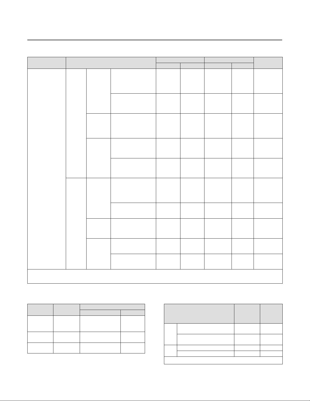
Table 1. Available Configurations
TYPE
NUMBER
(1)
MODES OPTIONS
Proportional‐
Only
Proportional‐
Plus‐Reset
Proportional‐
Plus‐Reset‐
Plus‐Rate
Differential
Gap
Anti‐Reset
Windup
(suffix letter F)
Remote
Set Point
(suffix letter M)
Internal Auto/
Manual Station
(suffix letter E)
4195KA
4195KAE
4195KAM
4195KAME
X
X
X
X
- - -
- - -
- - -
- - -
- - -
- - -
- - -
- - -
- - -
- - -
- - -
- - -
- - -
- - -
- - -
- - -
- - -
- - -
X
X
- - -
X
- - -
X
4195KB
4195KBE
4195KBF
4195KBFE
4195KBM
4195KBME
4195KBFM
4195KBFME
- - -
- - -
- - -
- - -
- - -
- - -
- - -
- - -
X
X
X
X
X
X
X
X
- - -
- - -
- - -
- - -
- - -
- - -
- - -
- - -
- - -
- - -
- - -
- - -
- - -
- - -
- - -
- - -
- - -
- - -
X
X
- - -
- - -
X
X
- - -
- - -
- - -
- - -
X
X
X
X
- - -
X
- - -
X
- - -
X
- - -
X
4195KC
4195KCE
4195KCF
4195KCFE
4195KCM
4195KCME
4195KCFM
4195KCFME
- - -
- - -
- - -
- - -
- - -
- - -
- - -
- - -
- - -
- - -
- - -
- - -
- - -
- - -
- - -
- - -
X
X
X
X
X
X
X
X
- - -
- - -
- - -
- - -
- - -
- - -
- - -
- - -
- - -
- - -
X
X
- - -
- - -
X
X
- - -
- - -
- - -
- - -
X
X
X
X
- - -
X
- - -
X
- - -
X
- - -
X
4195KS
4195KSE
4195KSM
4195KSME
- - -
- - -
- - -
- - -
- - -
- - -
- - -
- - -
- - -
- - -
- - -
- - -
X
X
X
X
- - -
- - -
- - -
- - -
- - -
- - -
X
X
- - -
X
- - -
X
1. Reverse‐acting constructions are designated by the suffix letter R in the type number.

4195K Pressure Controllers
D200050X012
Product Bulletin
34.5:4195K
July 2014
4
Features
n Easy Maintenance—Simple design allows fast, easy
maintenance and minimal spare parts inventory.
n Easy Adjustment—Adjusting the set point, the zero
and span of the process pointer, and switching
between direct and reverse action are accomplished
quickly and without special tools. Additionally, the
set point and proportional band can be adjusted
with no interaction between the two adjustments.
n Application Versatility—Either a Bourdon tube or
capsular input element is available to control a wide
range of positive pressures, vacuum pressures, or
compound pressures.
n Mounting Versatility—A 4195K controller can be
mounted directly on the actuator or it can mount
on a pipestand, wall, or in a panel.
n Vibration Resistance—The simple design and low
mass of internal parts allow a 4195K controller to
withstand the vibration levels encountered in most
plant environments.
n High‐Visibility Display—Two red pointers on a
114 mm (4 1/2‐inch) long, white‐on‐black scale
show process pressure and deviation from set point
at a glance. Two other gauges monitor supply
pressure and output pressure.
n Low Air/Gas Consumption—The relay and nozzle
design reduces the steady-state consumption rate
to as low as 0.09 m
3
/hr (3.5 scfh); less than the
6 scfh requirement set for the oil and gas industry
by the US Environmental Protection Agency (New
Source Performance Standards Subpart OOOO,
EPA‐HQ‐QAR‐2010-0505).
n Corrosion Resistance—Tough, plastic housing resists
such corrosive environments as chemical plants and
the salt spray atmosphere on an offshore oil
platform. Internal constructions are available to
resist a corrosive supply pressure media.
Construction Features
Simplified Relay Maintenance
A clean‐out wire provides a fast, easy means of
cleaning the relay primary orifice during service.
Pressure Protection for the Case
A rubber plug in the plastic case pops out to relieve
excessive pressure buildup inside the case.
Easy Direct/Reverse Switching
Controller action can be switched from direct to
reverse or vice versa by simply loosening the screws on
the proportional band cover and moving the cover out
to rotate the proportional band knob to the desired
action (see figure 1).
Easy Mode Conversion
Conversion from proportional to
proportional‐plus‐reset control requires the addition
of a reset valve and two pieces of tubing. Conversion
from proportional to proportional‐plus‐reset‐plus‐rate
control requires the addition of a reset/rate valve and
three pieces of tubing. Conversion from proportional
to differential gap for on/off control requires the
addition of one piece of tubing.
Anti‐Reset Windup
Anti‐reset windup is available with
proportional‐plus‐reset controllers. A relief valve may
be installed to limit reset windup in either direction.
Remote Set Point
The capability to adjust the set point from a remote
location is available as an option on 4195K controllers.
Auto/Manual Capability
An optional internal auto/manual station permits
smooth, bumpless transfer between automatic control
and manual operation without disturbing the
controller output. A positive‐acting, two‐position
switch, showing either automatic or manual control
mode, is clearly visible with the controller cover
closed.
4195K Pressure Controllers
D200050X012
Product Bulletin
34.5:4195K
July 2014
5
Table 2. Process Sensor (Capsular Element) Pressure Ratings
CAPSULE
MATERIAL
CAPSULAR
STANDARD RANGES
SPAN
(1)
OPERATING RANGE
OPERATING
LIMIT
(2)
Min Max Min Max
N09902
Nickel Alloy
Metric
units
Positive
pressure
0 to 150 mbar
0 to 400 mbar
0 to 0.6 bar
0.2 to 1 bar
0 to 1 bar
100 mbar
350 mbar
0.35 bar
0.4 bar
0.5 bar
160 mbar
700 mbar
0.7 bar
0.8 bar
1 bar
-350 mbar
-1 bar
-1 bar
-1 bar
-1 bar
350 mbar
1 bar
1 bar
1.4 bar
1.4 bar
510 mbar
1.5 bar
1.5 bar
2 bar
2 bar
0 to 1.4 bar
0 to 1.6 bar
0.4 to 2 bar
0 to 2 bar
0.7 bar
1 bar
0.8 bar
1 bar
1.4 bar
2 bar
1.6 bar
2 bar
-1 bar
-1 bar
-1 bar
-1 bar
1.7 bar
2.4 bar
2 bar
2.4 bar
2.5 bar
3.5 bar
3 bar
3.5 bar
Vacuum
-150 to 0 mbar
-340 to 0 mbar
-400 to 0 mbar
-0.6 to 0 bar
-1 to 0 bar
85 mbar
170 mbar
350 mbar
0.35 bar
0.5 bar
170 mbar
340 mbar
700 mbar
0.7 bar
1 bar
-350 mbar
-480 mbar
-1 bar
-1 bar
-1 bar
350 mbar
480 mbar
1 bar
1 bar
1.4 bar
510 mbar
724 mbar
1.5 bar
1.5 bar
2 bar
Compound
-50 to 100 mbar
-175 to 175 mbar
-150 to 250 mbar
-0.2 to 0.4 bar
100 mbar
175 mbar
350 mbar
0.35 bar
160 mbar
350 mbar
700 mbar
0.7 bar
-350 mbar
-480 mbar
-1 bar
-1 bar
350 mbar
480 mbar
1 bar
1 bar
510 mbar
724 mbar
1.5 bar
1.5 bar
-0.4 to 0.6 bar
-0.6 to 0.8 bar
-1 to 0.6 bar
-1 to 1 bar
0.5 bar
0.7 bar
1 bar
1 bar
1 bar
1.4 bar
2 bar
2 bar
-1 bar
-1 bar
-1 bar
-1 bar
1.4 bar
1.7 bar
2.4 bar
2.4 bar
2 bar
2.5 bar
3.5 bar
3.5 bar
U.S. units
Positive
pressure
0 to 60 inch wc
0 to 5 psig
0 to 10 psig
3 to 15 psig
0 to 15 psig
40 inch wc
2.5 psig
5 psig
6 psig
7.5 psig
60 inch wc
5 psig
10 psig
12 psig
15 psig
-10 inch Hg
-14 inch Hg
-30 inch Hg
-30 inch Hg
-30 inch Hg
5 psig
7 psig
15 psig
20 psig
20 psig
7.5 psig
10.5 psig
22.5 psig
30 psig
30 psig
0 to 20 psig
6 to 30 psig
0 to 30 psig
10 psig
12 psig
15 psig
20 psig
24 psig
30 psig
-30 inch Hg
-30 inch Hg
-30 inch Hg
25 psig
30 psig
35 psig
37.5 psig
45 psig
52.5 psig
Vacuum
-5 to 0 inch Hg
-10 to 0 inch Hg
-20 to 0 inch Hg
-30 to 0 inch Hg
2.5 inch Hg
5 inch Hg
10 inch Hg
15 inch Hg
5 inch Hg
10 inch Hg
20 inch Hg
30 inch Hg
-10 inch Hg
-14 inch Hg
-30 inch Hg
-30 inch Hg
5 psig
7 psig
15 psig
20 psig
7.5 psig
10.5 psig
22.5 psig
30 psig
Compound
-30 to 30 inch wc
-5 inch Hg to 2.5 psig
-10 inch Hg to 5 psig
40 inch wc
2.5 psig
5 psig
60 inch wc
5 psig
10 psig
-10 inch Hg
-14 inch Hg
-30 inch Hg
5 psig
7 psig
15 psig
7.5 psig
10.5 psig
22.5 psig
-15 inch Hg to 7.5 psig
-20 inch Hg to 10 psig
-30 inch Hg to 15 psig
7.5 psig
10 psig
15 psig
15 psig
20 psig
30 psig
-30 inch Hg
-30 inch Hg
-30 inch Hg
20 psig
25 psig
35 psig
30 psig
37.5 psig
52.5 psig
1. Minimum or maximum span or any span in between may be positioned anywhere within the operating range. For example, if a 0 to 350 mbar (0 to 5 psig) sensing element is used and the
minimum span of 175 mbar (2.5 psig) is set, the process indication can be calibrated to a range of 340 mbar to 203 mbar (10 inch Hg to 6 inch Hg), 0 to 172 mbar (0 to 2.5 psig), 172 to 345
mbar (2.5 to 5 psig), 305 to 480 mbar (4.5 to 7 psig), or any value between minimum and maximum values of operating range.
2. Capsules with the travel stops set may be pressured to this value without permanent zero shift.
Table 3. Optional Process Connection Adaptors
BAR INPUT
RANGE
PSIG INPUT
RANGE
CONNECTION
Size Material
Up to
0 to 400
Up to
0 to 5000
1/2 NPT external or
1/2 NPT internal
steel or
stainless
steel
0 to 400 to
0 to 600
0 to 5000 to
0 to 10,000
1/2 NPT internal stainless
steel
0 to 400 to
0 to 600
0 to 5000 to
0 to 10,000
1/2 NPT external stainless
steel
Table 4. Supply Pressure Data
Output Signal Range
Normal
Operating
Supply
Pressure
(1)
Maximum
Pressure
Limit
(2)
Bar
0.2 to 1.0 or 0 and 1.4
(diff gap)
1.4 2.8
0.4 to 2.1 or 0 and 2.4
(diff gap)
2.4 2.8
Psig
3 to 15 or 0 and 20 (diff gap) 20 40
6 to 30 or 0 and 35 (diff gap) 35 40
1. If this pressure is exceeded, control stability may be impaired.
2. If this pressure is exceeded, damage to controller components may result.
 Loading...