


 Liebert® GXT4™


 User Manual – 5000VA ~ 10000VA (230V)


Important Safety Precautions
Save These Instructions
This manual contains important safety instructions. Read all safety and operating instructions before operating the uninterruptible power system (UPS). Adhere to all warnings on the unit and in this manual. Follow all operating and user instructions. This equipment can be operated by individuals without previous training.
This product is designed for commercial/industrial use only. It is not intended for use with life support and other designated ‘critical’ devices. Maximum load must not exceed that shown on the UPS rating label. The UPS is designed for data processing equipment. If uncertain, consult your dealer or local Emerson Network Power representative.
This UPS is designed for use on a properly earthed (grounded), 220-240 VAC, 50Hz or 60Hz supply, for installation by qualified personnel. A qualified electrician must review and approve customer supplied wiring, circuit breakers, intended loads and verify correct input, output and earth connections to ensure compliance with technical standards and local electrical codes of practice.
Installation instructions and warning notices only for use by qualified personnel are located after the UPS operator instructions in this manual.
Warning
The battery can present a risk of electrical shock and high short circuit current. The following precautions should be observed when replacing the battery pack:
Wear rubber gloves and boots
Remove rings, watches and other metal objects.
Use tools with insulated handles.
Do not lay tools or other metal objects on the batteries.
If the battery kit is damaged in any way or shows signs of leakage, contact your local Emerson representative immediately.
Do not dispose of batteries in a fire. The batteries may explode.
Handle, transport and recycle batteries in accordance with local regulations.
Warning
Although the Liebert GXT4 has been designed and manufactured to ensure personal safety, improper use can result in electrical shock or fire. To ensure safety, observe the following precautions:
Turn Off and unplug the Liebert GXT4 before cleaning it.
Clean the UPS with a dry cloth. Do not use liquid or aerosol cleaners.
Never block or insert any objects into the ventilation holes or other openings of the UPS.
Do not place the Liebert GXT4 power cord where it might be damaged.
Notice
If this UPS is supplied from an ‘IT’ electrical power system, the jumper on the rear panel must be disconnected. Refer to 8.8 IT Power System Configuration for details. If connecting to an ‘IT’ system, the installer must provide a 2-pole upstream circuit breaker. Refer to all local and national codes when installing the upstream breaker.
ELECTROMAGNETIC COMPATIBILITY—The Liebert® GXT4™ complies with the limits of Category C2, pursuant to IEC/EN/AS 62040-2. Operation is subject to the following conditions:
The output cables shall be no longer than 10m (32ft).
This device may not cause harmful interference.
This device must accept any interference received, including interference that may cause undesired operation. Operating this device in a residential area is likely to cause harmful interference that users must correct at their own expense.
The Liebert GXT4 series complies with the requirements of EMC Directive 2004/108/EC and the published technical standards. Continued compliance requires installation in accordance with these instructions and use of accessories approved by Emerson.
Notice
1.This is a Category C2 UPS product. In a residential environment, this product may cause radio interference, in which case the user may be required to take additional measures.
2.Operate the UPS in an indoor environment only in an ambient temperature range of 0-40°C (32-104°F). Install it in a clean environment, free from moisture, flammable liquids, gases and corrosive substances.
3.This UPS contains no user-serviceable parts except the internal battery pack. The UPS Enter push button do not electrically isolate internal parts. Under no circumstances attempt to gain access internally due to the risk of
electric shock or burn.
4.Do not continue to use the UPS if the front panel indications are not in accordance with these operating instructions or the UPS performance alters in use. Refer all faults to your dealer.
5.Servicing of batteries should be performed or supervised by personnel knowledgeable of batteries and the required precautions. Keep unauthorized personnel away from the batteries. Keep unauthorized personnel away from the batteries. Proper disposal of batteries is required. Refer to your local laws and regulations for disposal requirements.
6.Never block or insert any object into the ventilation holes or other openings.
7.DO NOT CONNECT equipment that could overload the UPS or demand DC current from the UPS, for example: electric drills, vacuum cleaners, laser printers, hair dryers or any appliance using halfwave rectification.
8.Storing magnetic media on top of the UPS may result in data loss or corruption.
9.Turn Off and isolate the UPS before cleaning it. Use only a soft cloth, never liquid or aerosol cleaners.
Information for the Protection of the Environment
UPS SERVICING—This UPS makes use of components dangerous for the environment (electronic cards, electronic components). The components removed must be taken to specialized collection and disposal centers.
NOTICE TO EUROPEAN UNION CUSTOMERS: DISPOSAL OF OLD APPLIANCES—This product has been supplied from an environmentally aware manufacturer that complies with the Waste Electrical and Electronic Equipment (WEEE) Directive 2002/96/CE.
The ‘crossed-out wheelie bin’ symbol at right is placed on this product to encourage you to recycle wherever possible. Please be environmentally responsible and recycle this product through your recycling facility at its end of life. Do not dispose of this product as unsorted municipal waste. Follow local municipal waste ordinances for proper disposal provisions to reduce the environmental impact of waste electrical and electronic equipment (WEEE).
For information regarding the scrapping of this equipment, please browse http://www.eu.emersonnetworkpower.com (‘Products session’ or ‘Contact us’ session) or call our worldwide technical support.
Toll Free: 00 80011554499
Toll Number Based in Italy: +39 0298250222
|
Contents |
|
Chapter 1 Introduction ................................................................................................................................................. |
1 |
|
Chapter 2 System Description...................................................................................................................................... |
2 |
|
2.1 |
Transient Voltage Surge Suppression (TVSS) and EMI/RFI Filters .................................................................. |
2 |
2.2 |
Rectifier/Power Factor Correction (PFC) Circuit .............................................................................................. |
2 |
2.3 |
Inverter.......................................................................................................................................................... |
2 |
2.4 |
Battery Charger ............................................................................................................................................. |
2 |
2.5 |
DC-to-DC Converter....................................................................................................................................... |
2 |
2.6 |
Battery........................................................................................................................................................... |
3 |
2.7 |
Dynamic Bypass............................................................................................................................................ |
3 |
Chapter 3 Major Components ...................................................................................................................................... |
4 |
|
3.1 |
Main Frame and Electronics........................................................................................................................... |
4 |
3.2 |
Removable Power Distribution Box................................................................................................................. |
5 |
3.3 |
Internal Battery Packs .................................................................................................................................... |
6 |
Chapter 4 What’s Included........................................................................................................................................... |
7 |
|
Chapter 5 Installation and Configuration....................................................................................................................... |
8 |
|
5.1 |
Install Main Cabinet ....................................................................................................................................... |
8 |
|
5.1.1 Tower UPS Installation........................................................................................................................ |
8 |
|
5.1.2 Rack-Mount UPS Installation............................................................................................................... |
9 |
|
5.1.3 Installing Adjustable Rack-Mount Kit—Sold Separately......................................................................... |
9 |
5.2 |
External Battery Cabinet Installation .............................................................................................................. |
12 |
5.3 |
Connect Input/Output Power ......................................................................................................................... |
14 |
Chapter 6 Configuration Program................................................................................................................................ |
17 |
|
6.1 |
Configuration Program Features.................................................................................................................... |
17 |
6.2 What You Will Need...................................................................................................................................... |
17 |
|
Chapter 7 Operation And Display Panel ...................................................................................................................... |
18 |
|
7.1 |
LED Indicators .............................................................................................................................................. |
18 |
7.2 |
Control Buttons............................................................................................................................................. |
18 |
7.3 |
LCD Display Panel........................................................................................................................................ |
19 |
|
7.3.1 Startup Screen................................................................................................................................... |
19 |
|
7.3.2 ON Screen......................................................................................................................................... |
19 |
|
7.3.3 Default Screen ................................................................................................................................... |
19 |
|
7.3.4 Main Menu Screen ............................................................................................................................. |
20 |
|
7.3.5 Prompt List ........................................................................................................................................ |
24 |
|
7.3.6 Warning List....................................................................................................................................... |
25 |
|
7.3.7 Fault List............................................................................................................................................ |
26 |
Chapter 8 Operation ................................................................................................................................................... |
27 |
|
8.1 |
Startup Checklist For Liebert GXT4™............................................................................................................ |
27 |
8.2 |
Initial Startup And Electrical Checks .............................................................................................................. |
27 |
8.3 |
Manual Battery Test...................................................................................................................................... |
27 |
8.4 |
Put Liebert® GXT4™ In Bypass .................................................................................................................... |
27 |
8.5 |
Shut Down Liebert GXT4............................................................................................................................... |
28 |
8.6 |
Disconnecting Input Power From Liebert GXT4.............................................................................................. |
28 |
8.7 |
Maintenance Bypass..................................................................................................................................... |
28 |
8.8 |
IT Power System Configuration ..................................................................................................................... |
28 |
Chapter 9 Communication........................................................................................................................................... |
30 |
|
9.1 |
Communication Interface Port ....................................................................................................................... |
30 |
9.2 |
Terminal Block.............................................................................................................................................. |
30 |
|
9.2.1 Any-Mode Shutdown.......................................................................................................................... |
30 |
|
9.2.2 Battery Mode Shutdown ..................................................................................................................... |
30 |
|
9.2.3 On Battery ......................................................................................................................................... |
31 |
|
9.2.4 Low Battery........................................................................................................................................ |
31 |
9.3 |
Liebert IntelliSlot® Communication Cards...................................................................................................... |
31 |
|
9.3.1 Liebert® MultiLink®............................................................................................................................ |
31 |
9.4 |
Remote Emergency Power Off ...................................................................................................................... |
32 |
Chapter 10 Maintenance............................................................................................................................................. |
33 |
|
10.1 Replacing Internal Battery Pack................................................................................................................... |
33 |
|
10.2 Battery Charging......................................................................................................................................... |
35 |
|
10.3 Precautions................................................................................................................................................. |
35 |
|
10.4 Checking UPS Status.................................................................................................................................. |
35 |
|
10.5 Checking UPS Functions............................................................................................................................. |
35 |
|
Chapter 11 Specifications ........................................................................................................................................... |
36 |
|
Chapter 12 Product Warranty Registration................................................................................................................... |
40 |
|

Chapter 1 Introduction |
1 |
Chapter 1 Introduction
Congratulations on your choice of the Liebert® GXT4™ uninterruptible power system (UPS). The Liebert GXT4 comes in nominal power ratings of 5000VA, 6000VA and 10,000VA. It is designed to provide conditioned power to microcomputers and other sensitive electronic equipment.
When it is generated, alternating current is clean and stable. However, during transmission and distribution it is subject to voltage sags, spikes and complete power failure that may interrupt computer operations, cause data loss and even damage equipment. The Liebert GXT4 protects equipment from these disturbances.
The Liebert GXT4 is a compact, on-line UPS. An on-line UPS continuously conditions and regulates its output voltage, whether utility power is present or not. It supplies connected equipment with clean, sinewave power. Sensitive electronic equipment operates best from sinewave power.
The Liebert GXT4 features a multicolor LCD display to indicate load percentage, input/output voltage and current, runtime of battery and so on. It also provides self-diagnostic tests by visual configuration.
The Liebert GXT4 can be operated at high efficiency mode (Green Mode) which efficiency could up to 97%. The Liebert GXT4 includes E models without rack slide kits for different requirement of user.
The Liebert GXT4 has a Liebert IntelliSlot® port for communication between the UPS and a network server or other computer systems. This port provides detailed operating information including voltages, currents and alarm status to the host system when used in conjunction with Liebert MultiLink®. Liebert MultiLink can also remotely control UPS operation.
Liebert GXT4 UPS 5000VA ~ 10000VA (230V) User Manual
2 |
Chapter 2 System Description |
Chapter 2 System Description
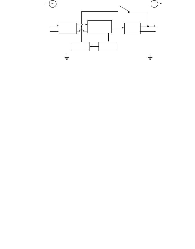
The operating principle of the UPS is shown in Figure 2-1.
Input |
|
|
Dynamic Bypass |
Output |
|
L1 |
TVSS & |
|
Rectifier/PFC |
|
L1 |
|
DC-to-DC |
Inverter |
|||
N |
EMI/RFI |
|
Converter |
N |
|
Filters |
|
|
|||
|
|
|
|||
|
|
Battery |
Battery |
|
|
|
|
charger |
|
|
|
|
|
|
|
|
|
G 


 G
G
Figure 2-1 Operating principle diagram
2.1 Transient Voltage Surge Suppression (TVSS) and EMI/RFI Filters
These UPS components provide surge protection and filter both electromagnetic interference (EMI) and radio frequency interference (RFI). They minimize any surges or interference present in the utility line and keep the sensitive equipment protected.
2.2 Rectifier/Power Factor Correction (PFC) Circuit
In normal operation, the rectifier/power factor correction (PFC) circuit converts utility AC power to regulated DC power for use by the inverter while ensuring that the waveshape of the input current used by the UPS is near ideal. Extracting this sinewave input current achieves two objectives:
The utility power is used as efficiently as possible by the UPS.
The amount of distortion reflected on the utility is reduced.
This results in cleaner power being available to other devices in the building not being protected by the Liebert® GXT4™.
2.3 Inverter
In normal operation, the inverter utilizes the DC output of the power factor correction circuit and inverts it into precise, regulated sinewave AC power. Upon a utility power failure, the inverter receives its required energy from the battery through the DC-to-DC converter. In both modes of operation, the UPS inverter is on-line and continuously generating clean, precise, regulated AC output power.
2.4 Battery Charger
The battery charger utilizes energy from the utility power and precisely regulates it to continuously float charge the batteries. The batteries are being charged whenever the Liebert GXT4 is connected to mains power.
2.5 DC-to-DC Converter
The DC-to-DC converter utilizes energy from the battery system and raises the DC voltage to the optimum operating voltage for the inverter. This allows the inverter to operate continuously at its optimum efficiency and voltage, thus increasing reliability.
Liebert GXT4 UPS 5000VA ~ 10000VA (230V) User Manual
Chapter 2 System Description |
3 |
2.6 Battery
The Liebert® GXT4™ utilizes valve-regulated, nonspillable, lead acid batteries. To maintain battery design life, operate the UPS in an ambient temperature of 15°C to 25°C (59°F to 77°F). Optional external battery cabinets are available to extend battery run times. For run times, see Table 11-5.
2.7 Dynamic Bypass
The Liebert GXT4 provides an alternate path for utility power to the connected load in the unlikely event of a UPS malfunction. Should the UPS have an overload, overtemperature or any other UPS failure condition, the UPS automatically transfers the connected load to bypass.
NOTE
The bypass power path does NOT protect the connected equipment from disturbances in the mains supply.
Liebert GXT4 UPS 5000VA ~ 10000VA (230V) User Manual
4 |
Chapter 3 Major Components |
Chapter 3 Major Components
The Liebert® GXT4™ is composed of three major assemblies to provide easier handling, installation and versatility.
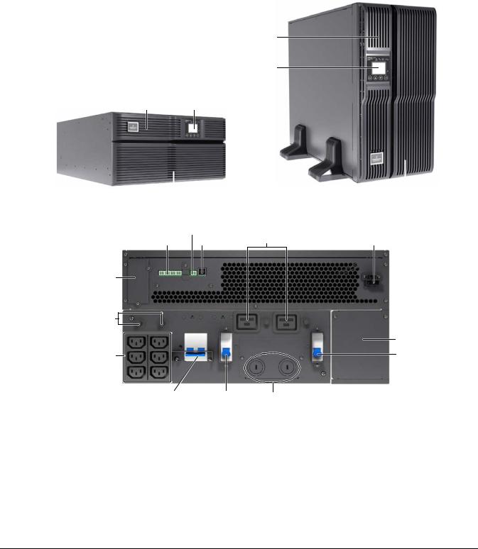
3.1 Main Frame and Electronics
The cabinet is shipped with internal batteries installed and a basic, hardwire distribution box attached and ready to install.
Note: 10,000VA model's front layout is identical; the battery compartment is larger.
Upper Bezel
Operation and display panel
Operation and
Upper Bezel display panel
Lower bezel and |
|
battery access door |
|
|
|
|
|
||
|
Lower bezel and battery access door |
|||
|
||||
Figure 3-1 Liebert GXT4 5000VA and 6000VA (front view)
REPO connection block |
C19 output power |
|
Terminal block communication USB port |
receptacles |
External battery connector |
Liebert IntelliSlot port
Output circuit |
|
|
breakers |
|
|
|
|
IT power system |
C13 output |
|
access cover |
|
Input circuit breaker |
|
receptacles |
|
|
|
|
|
Maintenance |
Output circuit |
Knockouts for |
bypass breaker |
breaker |
hardwired power input |
Liebert GXT4 5000VA and 6000VA
Liebert GXT4 UPS 5000VA ~ 10000VA (230V) User Manual
|
|
|
|
|
|
|
|
|
|
|
|
|
|
|
|
|
|
|
|
|
|
|
|
|
|
|
|
Chapter 3 Major Components |
5 |
|||
|
|
|
|
|
|
|
Reserved |
|
|
|
|
|
C19 output power receptacles |
|
||||||||||||||||||
REPO |
|
|
|
|
|
|
|
|
|
USB port |
|
|
|
Output circuit |
breaker |
|
||||||||||||||||
|
|
|
|
|
|
|
|
|
|
|
|
|||||||||||||||||||||
|
|
|
|
|
|
|
|
|
|
|
|
|
|
|
|
|
|
|
|
|
|
|
|
|
|
|
|
|
|
|
|
|
|
|
|
|
|
|
|
|
|
|
|
|
|
|
|
|
|
|
|
|
|
|
|
|
|||||||||
|
|
|
|
|
|
|
|
|
|
|
|
|
|
|
|
|
|
|
|
|
|
|
||||||||||
|
|
|
|
|
|
|
|
|
|
|
|
|
|
|
|
|
|
|
|
|
|
|
|
|
|
|
||||||
Terminal block |
|
|
|
|
|
|
|
|
|
|
|
|
|
|
|
|
|
|
|
|
|
|
|
|
|
|
|
|
|
|
||
|
|
|
|
|
|
|
|
|
|
|
|
|
|
|
|
|
|
|
|
|
|
|
|
|
|
|
|
|||||
communication |
|
|
|
|
|
|
|
|
|
|
|
|
|
|
|
|
|
|
|
|
||||||||||||
Maintenance |
|
|
|
|
|
|
|
|
|
|
|
|
|
|
|
|
|
|
|
|
||||||||||||
|
|
|
|
|
|
|
|
|
|
|
|
|
|
|
|
|
|
|
|
|||||||||||||
bypass breaker |
|
|
|
|
|
|
|
|
|
|
|
|
|
|
|
|
|
|
|
|
|
|||||||||||
Input circuit |
|
|
|
|
|
|
|
|
|
|
|
|
|
|
|
|
|
|
|
|
External battery |
|
||||||||||
breaker |
|
|
|
|
|
|
|
|
|
|
|
|
|
|
|
|
|
|
|
|
|
|
|
|
||||||||
|
|
|
|
|
|
|
|
|
|
|
|
|
|
|
|
|
|
|
|
|
connector |
|
||||||||||
Output circuit |
|
|
|
|
|
|
|
|
|
|
|
|
|
|
|
|
|
|
|
|
|
|
|
|
|
|
||||||
|
|
|
|
|
|
|
|
|
|
|
|
|
|
|
|
|
|
|
|
|
Liebert IntelliSlot |
|
||||||||||
|
|
|
|
|
|
|
|
|
|
|
|
|
|
|
|
|
|
|
|
|||||||||||||
breaker |
|
|
|
|
|
|
|
|
|
|
|
|
|
|
|
|
|
|
|
|||||||||||||
|
|
|
|
|
|
|
|
|
|
|
|
|
|
|
|
|
|
|
|
|
|
|
|
|
|
|
|
|
|
|
port |
|
|
|
|
|
|
|
|
|
|
|
|
|
|
|
|
|
|
|
|
|
|
|
|
|
|
|
|||||||
C13 output |
|
|
|
|
|
|
|
|
|
|
|
|
|
|
|
|
|
|
|
|
|
|
|
|
|
|
|
|
||||
receptacles |
|
|
|
|
|
|
|
|
|
|
|
|
|
|
|
|
|
|
|
|
|
|
|
|
|
|||||||
|
|
|
|
|
|
|
|
|
|
|
|
|
|
|
|
|
|
|
|
|||||||||||||
|
|
|
|
|
|
|
|
|
|
|
|
|
|
|
|
|
|
|
|
|
|
|
|
|
|
|
|
|
|
|||
|
|
|
|
|
|
|
|
|
|
|
|
|
|
|
|
|
|
|
|
|
|
|
|
|
|
|
|
|
|
|
|
|
|
|
|
|
|
|
|
|
|
|
|
|
|
|
|
|
|
|
|
|
|
|
|
|
|
|
|
|
|
||||
|
|
|
|
|
|
|
|
|
|
|
Output circuit |
Knockouts for |
IT power system |
|
||||||||||||||||||
|
|
|
|
|
|
|
|
|
|
|
|
|
breaker hardwired power input |
access cover |
|
|||||||||||||||||
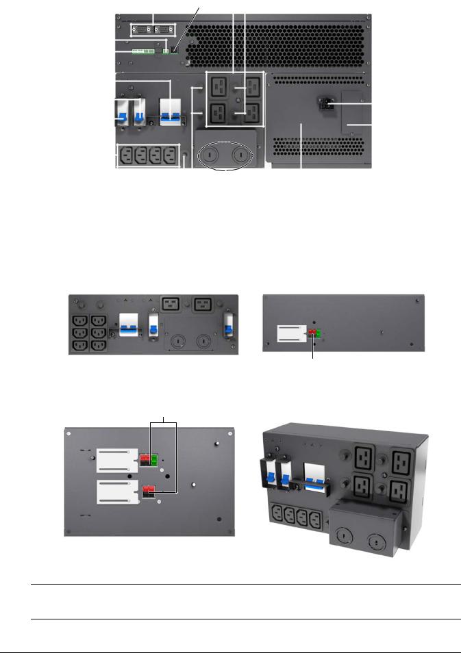
Liebert GXT4 10,000VA
Figure 3-2 Liebert® GXT4™ (rear view)
3.2 Removable Power Distribution Box
The UPS is shipped with a power distribution pack installed, as shown in Figure 3-3 and Figure 3-4. This box contains the UPS input circuit breaker.
Outer surface view of power distribution box |
Quick-connect |
for 5000VA and 6000VA models |
|
PD2-CE6HDWRMBS |
|
Figure 3-3 Power distribution box for GXT4 5000VA and 6000VA models
Quick-connect
Inner surface view of power distribution box |
Front view |
for 10000VA model (PD2-CE10HDWRMBS) |
Figure 3-4 Power distribution box for GXT4 10,000VA model
Note
Hardwire and hardwire/receptacle boxes that include a manual bypass switch allow AC power to continue to flow from the mains input to the load while the box is removed from the UPS. For details, refer to 5.3 Connect Input/Output Power.
Liebert GXT4 UPS 5000VA ~ 10000VA (230V) User Manual
6 |
Chapter 3 Major Components |
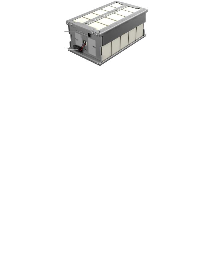
3.3 Internal Battery Packs
The UPS has two internal battery packs behind a battery access door on the front of the unit. Each internal battery pack is fitted with a connector to link to the UPS.
Battery handle
Battery connector
Front of battery pack
Figure 3-5 Internal battery pack features
Liebert GXT4 UPS 5000VA ~ 10000VA (230V) User Manual

Chapter 4 What’s Included |
7 |
Chapter 4 What’s Included
The Liebert® GXT4™ is shipped with the following items:
Terminal Block Communication terminals
Compact disc with:
Liebert MultiLink®
Configuration program & Multi-languages package
User manual (electronic version)
USB cable, one; 2m (6-1/2 ft.) long
Mounting hardware, including screws and handles
Rack slide kits(E models do not include)
Power Distribution Box, installed on Liebert GXT4
Support base set, one
Warnings, safety instructions booklet and WEEE recycling sheet (ISO 14001 compliance)
Note
The Liebert GXT4 External Battery Cabinet shipping package includes one battery cabinet, two spacers for tower configuration and one DC power cable.
Liebert GXT4 UPS 5000VA ~ 10000VA (230V) User Manual
 Loading...