


Instruction Manual |
EH (1-1/2x1 through 8x6) |
D100394X012 |
December 2014 |
|
|
Fisherr EHD, EHS, and EHT Valves
NPS 1-1/2x1 through NPS 8x6
Contents |
|
|
|
Figure 1. Fisher EH Valve with 657 Actuator |
|
Introduction . . . . . . . . . . . . . . . . . . . . . . . . . . . . . . . . . |
1 |
|
Scope of Manual . . . . . . . . . . . . . . . . . . . . . . . . . . . . . |
1 |
|
Description . . . . . . . . . . . . . . . . . . . . . . . . . . . . . . . . . |
2 |
|
Specifications . . . . . . . . . . . . . . . . . . . . . . . . . . . . . . . |
3 |
|
Educational Services . . . . . . . . . . . . . . . . . . . . . . . . . |
3 |
|
Installation . . . . . . . . . . . . . . . . . . . . . . . . . . . . . . . . . . |
4 |
|
Maintenance . . . . . . . . . . . . . . . . . . . . . . . . . . . . . . . . . |
6 |
|
Packing Lubrication . . . . . . . . . . . . . . . . . . . . . . . . . . |
7 |
|
Packing Maintenance . . . . . . . . . . . . . . . . . . . . . . . . . |
7 |
|
Replacing Packing . . . . . . . . . . . . . . . . . . . . . . . . |
8 |
|
Trim Removal . . . . . . . . . . . . . . . . . . . . . . . . . . . . . . |
12 |
|
Valve Plug Maintenance . . . . . . . . . . . . . . . . . . . . . |
15 |
|
Lapping Seats . . . . . . . . . . . . . . . . . . . . . . . . . . . . . . |
16 |
|
Trim Replacement . . . . . . . . . . . . . . . . . . . . . . . . . . |
16 |
|
Retrofit: Installing C-seal Trim . . . . . . . . . . . . . . . . |
22 |
|
Replacement of Installed C-seal Trim . . . . . . . . . . . |
25 |
|
Trim Removal (C-seal Constructions) . . . . . . . |
25 |
|
Lapping Metal Seats (C-seal Constructions) . . |
27 |
|
Remachining Metal Seats |
|
|
(C-seal Constructions) . . . . . . . . . . . . . . . . . |
27 |
|
Trim Replacement (C-seal Constructions) . . . |
27 |
|
Parts Ordering . . . . . . . . . . . . . . . . . . . . . . . . . . . . . . . |
29 |
|
Parts Kits . . . . . . . . . . . . . . . . . . . . . . . . . . . . . . . . . . . |
29 |
|
Parts List . . . . . . . . . . . . . . . . . . . . . . . . . . . . . . . . . . . |
30 |
W3387 |
|
|
|
Introduction
Scope of Manual
This instruction manual includes installation, maintenance, and parts information for the Fisher EHD, EHS, and EHT control valves in NPS 1-1/2 x 1 through NPS 8x6. Refer to separate manuals for instructions covering the actuator, positioner, ENVIRO-SEALt packing, HIGH-SEAL packing, and accessories.
Do not install, operate, or maintain EHD, EHS, or EHT valves without being fully trained and qualified in valve, actuator, and accessory installation, operation, and maintenance. To avoid personal injury or property damage, it is important to carefully read, understand, and follow all the contents of this manual, including all safety cautions and warnings. If you have any questions about these instructions, contact your Emerson Process Management sales office before proceeding.
Unless otherwise noted, all NACE references are to NACE MR0175-2002.
www.Fisher.com

EH (1-1/2x1 through 8x6) |
Instruction Manual |
December 2014 |
D100394X012 |
|
|
Table 1. Specifications
End Connection Styles
Buttwelding: All available ASME B16.25 schedules that are compatible with ASME B16.34 pressure/temperature ratings
Flanged: CL2500 J ring-type joint (RTJ) or
J raised-face (RF) flanges according to ASME B16.5 Socket Welding: Consistent with ASME B16.11
Maximum Inlet Pressure(1)
Buttwelding: Consistent with CL2500 pressure-temperature ratings per ASME B16.34 Flanged: Consistent with CL2500 pressure-temperature ratings per ASME B16.34 Socket Welding: Consistent with CL2500 pressure-temperature ratings per ASME B16.34
Shutoff Classifications
See table 2
C-seal trim: High-temperature, Class V. See table 3
TSO (Tight Shutoff) trim: See tables 4 and 5
Flow Characteristic
Standard Cage: J Equal percentage, J modified equal percentage(2), J or linear
Cavitrolt III or Whisper Trimt III Cage: Linear
Flow Direction
EHD or EHT: Flow down, except with either a Whisper Trim III cage or a valve plug with diverter cone, both of which are flow up
EHS: Flow up, except flow down with Cavitrol III cage
Approximate Weights (Valve Body and Bonnet
Assemblies)
See table 6
Additional Specifications
For specifications such as materials, valve plug travels, and port, yoke boss, and stem diameters, see the Parts List section
1.The pressure or temperature limits in this manual and any applicable standard limitations should not be exceeded.
2.Modified equal percentage characteristic is equal-percentage for the first 90% of travel, then quick-opening for additional capacity.
Table 2. Shutoff Classifications per ANSI/FCI 70-2 and IEC 60534-4
Valve |
Valve Size, |
|
NPS |
||
|
||
|
3x2 |
|
|
|
|
|
3, 4x3, |
|
EHD |
4, 6x4 |
|
|
|
|
|
6, 8x6 |
|
|
|
|
EHS w/Cavitrol III, or |
All |
|
EHT w/Cavitrol III |
||
|
||
|
|
|
EHS, EHT, |
All |
|
EHS w/Micro-Form or |
||
EHS w/Micro Flute |
|
|
EHT w/ PEEK Anti-Extrusion |
3 to 6 |
|
Rings |
||
|
||
|
|
ANSI/FCI Leakage Class
II
II–Standard
III–Optional(1)
III–Standard
IV–Optional(1)
V(1)
IV–Standard
V–Optional(1)
V to 600_F (316_C)
1. O-ring seat ring construction recommended for this shutoff classification; for temperatures below 232_C (450_F) only.
Description
The EHD, EHS, and EHT high-pressure globe valves (figure 1) have metal seats, cage guiding, and push-down-to-close valve plug action. The EHD and EHT valves use balanced valve plugs.
The EHS valve uses an unbalanced valve plug. To provide a seal between the cage and a balanced valve plug, the EHD valve plug uses piston rings; the EHT valve plug uses a pressure-assisted seal ring. A Whisper Trim cage can be used with an EHD, EHS, or EHT valve plug. A Cavitrol III cage can be used with an EHS or EHT valve plug.
C-seal trim is available for EHD valves, CL2500, in sizes 4, 6, 6x4, and 8x6.
With C-seal trim, a balanced valve can achieve high-temperature, Class V shutoff. Because the C-seal plug seal is formed from metal (N07718 nickel alloy) rather than an elastomer, a valve equipped with the C-seal trim can be
2

Instruction Manual |
EH (1-1/2x1 through 8x6) |
D100394X012 |
December 2014 |
|
|
applied in processes with a fluid temperature of up to 593_C (1100_F), provided other material limits are not exceeded. Contact your Emerson Process Management sales office for information.
Specifications
Specifications for the EHD, EHS, and EHT valves are shown in table 1.
Educational Services
For information on available courses for the Fisher EH valve, as well as a variety of other products, contact:
Emerson Process Management Educational Services - Registration
Phone: 1-641-754-3771 or 1-800-338-8158 E-mail: education@emerson.com http://www.emersonprocess.com/education
Table 3. Additional Shutoff Classification per ANSI/FCI 70-2 and IEC 60534-4
Valve (Class) |
Valve Size, NPS |
Port Diameter, Inches |
Cage Style |
ANSI/FCI Leakage |
|
Class |
|||||
|
|
|
|
||
|
|
|
Equal Percentage, Modified Equal Percentage, |
|
|
|
4 |
2.875 |
Linear (std. cage), |
|
|
|
6x4 |
Linear (Whisper III, A1, B3, C3) |
|
||
|
|
V (for port |
|||
|
|
|
Linear (Cavitrol III, 2-stage) |
||
EHD |
|
|
diameters from 2.875 |
||
|
|
|
|||
|
|
Equal Percentage, Modified Equal Percentage, |
|||
(CL2500) |
6 |
4.375 |
through 7-inch with |
||
Linear (std. cage), |
|||||
|
8x6 |
optional C-seal trim) |
|||
|
|
Linear (Whisper III, A1, B3, C3, D3) |
|||
|
|
|
|
||
|
|
|
|
|
|
|
6 |
4.375 |
Linear (Cavitrol III, 2- and 3-stage) |
|
|
|
8x6 |
|
|||
|
|
|
|
||
|
|
|
|
|
Table 4. TSO (Tight Shutoff) Leakage Class per ANSI/FCI 70-2 and IEC 60534-4
Leakage Class |
Maximum Leakage |
Test Medium |
Test Pressure |
ANSI/FCI Leakage Class |
|
|
Valves with TSO trim are factory tested to |
|
|
|
|
TSO (Tight Shutoff) |
a more stringent Emerson Process |
Water |
Service P(1) |
V |
|
Management test requirement of no |
|||||
|
|
|
|
||
|
leakage at time of shipment. |
|
|
|
|
|
|
|
|
|
|
1. Specify service P when ordering. |
|
|
|
||
Table 5. TSO Shutoff Availability
VALVE |
|
|
CONSTRUCTION |
|
|
LEAKAGE CLASS |
|||
|
|
|
Standard |
Optional |
|||||
|
|
|
|
|
|
|
|||
EHS, EHT |
|
Cavitrol III trim. Replaceable, protected soft seat |
|
TSO |
- - - |
||||
|
|
|
|
|
|
|
|
|
|
Table 6. Approximate Weights (Valve Body and Bonnet Assemblies) |
|
|
|
|
|||||
|
|
|
|
|
|
|
|
|
|
|
|
|
|
CL2500 |
|
|
|
|
|
VALVE |
|
|
Kilograms |
|
|
Pounds |
|
||
SIZE, |
|
|
|
SWE |
|
|
|
|
SWE |
NPS |
|
Flg |
|
& |
|
Flg |
|
|
& |
|
|
|
|
BWE |
|
|
|
|
BWE |
1-1/2 x 1 |
|
- - - |
|
46 |
|
- - - |
|
|
101 |
|
|
|
|
|
|
|
|
|
|
2x1 |
|
78 |
|
47 |
|
173 |
|
|
104 |
|
|
|
|
|
|
|
|
|
|
3x2 |
|
161 |
|
94 |
|
355 |
|
|
207 |
|
|
|
|
|
|
|
|
|
|
3 |
|
223 |
|
163 |
|
492 |
|
|
359 |
|
|
|
|
|
|
|
|
|
|
4x3 |
|
265 |
|
162 |
|
585 |
|
|
357 |
|
|
|
|
|
|
|
|
|
|
4 |
|
338 |
|
243 |
|
745 |
|
|
536 |
|
|
|
|
|
|
|
|
|
|
6x4 |
|
526 |
|
257 |
|
1160 |
|
|
567 |
|
|
|
|
|
|
|
|
|
|
6 |
|
785 |
|
544 |
|
1731 |
|
|
1199 |
|
|
|
|
|
|
|
|
|
|
8x6 |
|
955 |
|
558 |
|
2106 |
|
|
1231 |
|
|
|
|
|
|
|
|
|
|
3

EH (1-1/2x1 through 8x6) |
Instruction Manual |
December 2014 |
D100394X012 |
|
|
Installation

 WARNING
Always wear protective gloves, clothing, and eyewear when performing any installation operations to avoid personal injury.
To avoid personal injury or property damage resulting from the sudden release of pressure, do not install the valve assembly where service conditions could exceed the limits given in this manual or on the appropriate nameplates. Use pressure-relieving devices as required by government or accepted industry codes and good engineering practices.
Check with your process or safety engineer for any additional measures that must be taken to protect against process media.
If installing into an existing application, also refer to the WARNING at the beginning of the Maintenance section in this instruction manual.
CAUTION
Responsibility for the safety of process media and compatibility of valve materials with process media rests solely with the purchaser and end-user. The valve configuration and construction materials meet particular pressure, temperature, pressure drop, and controlled fluid conditions specified in the customer's order. Because some body/trim material combinations are limited in their pressure drop and temperature range capabilities (especially due to differences in thermal expansion rates), do not apply any other conditions to the valve without first contacting your Emerson Process Management sales office.
CAUTION
If hoisting the valve, use a nylon sling to protect the painted surfaces. Carefully position the sling to prevent damage to the tubing or any accessories. Use adequately sized hoists and chains or slings to handle the valve and take precautions to prevent personnel from being injured in case the hoist or rigging slips unexpectedly. Refer to table 6 for valve assembly weights.

 WARNING
Personal injury could result from packing leakage. Valve packing was tightened prior to shipment; however some readjustment will be required to meet specific service conditions. Check with your process or safety engineer for any additional measures that must be taken to protect against process media.
1.Before installing the valve, inspect it to ensure that the valve body cavity is free of foreign material.
2.Clean out all pipelines to remove scale, welding slag, and other foreign materials before installing the valve.
Note
If the valve being installed has small internal flow passages, such as with Whisper Trim III or Cavitrol III cages, consideration should be given to installing an upstream strainer to prevent the lodging of particles in these passages. This is especially important if the pipeline cannot be thoroughly cleaned or if the flowing medium is not clean.
4
Instruction Manual |
EH (1-1/2x1 through 8x6) |
D100394X012 |
December 2014 |
|
|
3.The control valve must be installed with the actuator vertical above the valve body for proper operation. Flow through the valve must be in the direction indicated by the flow arrow (key 15, figure 17, 18, or 20) on the valve body.
4.Use accepted piping and welding practices when installing the valve in the line. For welding end valve bodies, completely disassemble the valve removing all trim parts before welding the valve body in the line. For flanged valve bodies, use suitable gaskets between the valve body flanges and pipeline flanges.
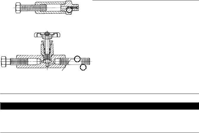
Figure 2. Lubricator and Lubricator/Isolating Valve
10A9421-A AJ5428-D A0832-2
 14
14
LUBRICATOR
14
 27
27
LUBRICATOR/ISOLATING VALVE
CAUTION
Depending on valve body materials used, post-weld heat treating might be needed. Post-weld heat treatment can damage internal elastomeric, plastic, and metal parts. Shrunk-fit pieces and threaded connections might loosen.
If post-weld heat treating is needed, remove all trim parts to avoid any damage to internal elastomeric, plastic, and metal parts. Contact your Emerson Process Management sales office for additional information.
5.Install a three-valve bypass around the valve if continuous operation is required during maintenance.
6.If the actuator and valve body are shipped separately, refer to the actuator mounting procedure in the appropriate actuator instruction manual.
7.If the valve was shipped without packing installed in the packing box, install the packing before putting the valve into service. Refer to instructions given in the Packing Maintenance procedure.
Valves with ENVIRO-SEAL live-loaded packing or HIGH-SEAL Heavy-Duty live-loaded packing will not require this initial re-adjustment. See the Fisher instruction manuals titled ENVIRO-SEAL Packing System for Sliding-Stem Valves or HIGH-SEAL Live-Loaded Packing System (as appropriate) for packing instructions. If you wish to convert your present packing arrangement to ENVIRO-SEAL packing, refer to the retrofit kits listed in the parts kit sub-section near the end of this manual.
5

EH (1-1/2x1 through 8x6) |
Instruction Manual |
December 2014 |
D100394X012 |
|
|
Maintenance
Valve parts are subject to normal wear and must be inspected and replaced as necessary. Inspection and maintenance frequency depends on the severity of service conditions. This section includes instructions for packing lubrication, packing maintenance, adding packing rings, replacing packing, trim removal, valve plug maintenance, lapping seats, and trim replacement. All maintenance operations can be performed with the valve in the line.

 WARNING
Avoid personal injury from sudden release of process pressure. Before performing any maintenance operations: D Do not remove the actuator from the valve while the valve is still pressurized.
DAlways wear protective gloves, clothing, and eyewear when performing any maintenance operations to avoid personal injury.
DDisconnect any operating lines providing air pressure, electric power, or a control signal to the actuator. Be sure the actuator cannot suddenly open or close the valve.
DUse bypass valves or completely shut off the process to isolate the valve from process pressure. Relieve process pressure on both sides of the valve. Drain the process media from both sides of the valve.
D Vent the power actuator loading pressure and relieve any actuator spring precompression.
D Use lock-out procedures to be sure that the above measures stay in effect while you work on the equipment.
DThe valve packing box may contain process fluids that are pressurized, even when the valve has been removed from the pipeline. Process fluids may spray out under pressure when removing the packing hardware or packing rings, or when loosening the packing box pipe plug.
DCheck with your process or safety engineer for any additional measures that must be taken to protect against process media.
Table 7. Recommended Torque for Packing Flange Nuts
STEM |
|
VALVE |
|
|
|
TORQUE |
|
|
||
DIAMETER |
|
BODY |
NSm |
|
|
|
LbfSFt |
|||
mm |
|
Inches |
RATING(1) |
Min |
|
Max |
|
Min |
|
Max |
12.7 |
|
1/2 |
CL1500 |
15 |
|
22 |
|
11 |
|
16 |
|
|
|
|
|
|
|
|
|
||
|
CL2500 |
18 |
|
24 |
|
13 |
|
18 |
||
|
|
|
|
|
|
|||||
|
|
|
|
|
|
|
|
|
|
|
19.1 |
|
3/4 |
CL1500 |
34 |
|
50 |
|
25 |
|
37 |
|
|
|
|
|
|
|
|
|
||
|
CL2500 |
41 |
|
61 |
|
30 |
|
45 |
||
|
|
|
|
|
|
|||||
|
|
|
|
|
|
|
|
|
|
|
25.4 |
|
1 |
CL1500 |
52 |
|
77 |
|
38 |
|
57 |
|
|
|
|
|
|
|
|
|
||
|
CL2500 |
61 |
|
91 |
|
45 |
|
67 |
||
|
|
|
|
|
|
|||||
|
|
|
|
|
|
|
|
|
|
|
31.8 |
|
1-1/4 |
CL1500 |
68 |
|
102 |
|
50 |
|
75 |
|
|
|
|
|
|
|
|
|
||
|
CL2500 |
81 |
|
122 |
|
60 |
|
90 |
||
|
|
|
|
|
|
|||||
|
|
|
|
|
|
|
|
|
|
|
1. Includes intermediate class ratings.
Note
Whenever a gasket seal is disturbed by removing or shifting gasketed parts, a new gasket should be installed upon reassembly. This is necessary to ensure a good gasket seal.
Note
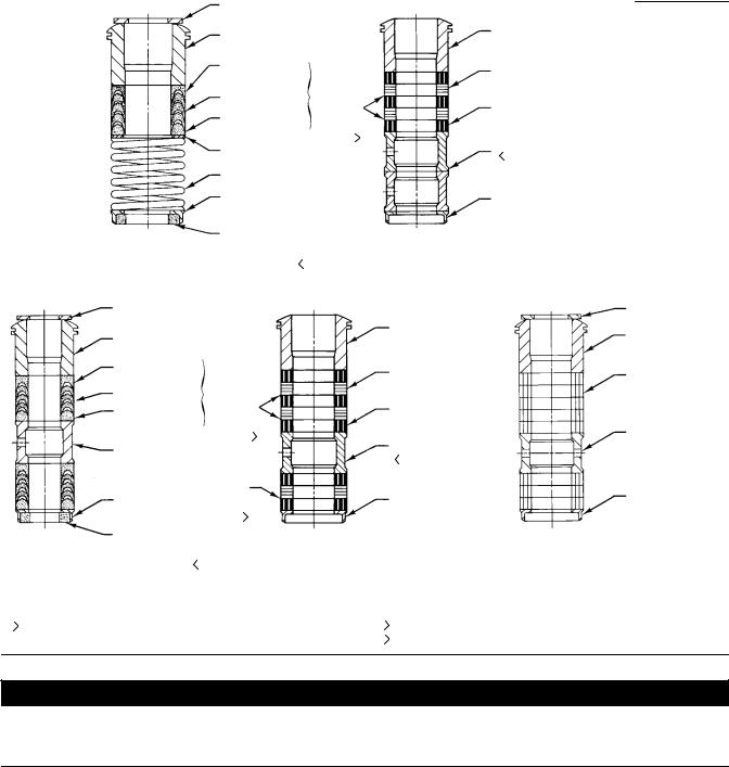
If the valve has ENVIRO-SEAL live-loaded packing installed (figure 3), see the Fisher instruction manual entitled ENVIRO-SEAL Packing System for Sliding Stem Valves for packing instructions.
If the valve has HIGH-SEAL heavy-duty live-loaded packing installed, see Fisher instruction manual entitled HIGH-SEAL Live-Loaded Packing Systems for packing instructions.
6

Instruction Manual |
EH (1-1/2x1 through 8x6) |
D100394X012 |
December 2014 |
|
|

 WARNING
Personal injury could result from packing leakage. Valve packing was tightened prior to shipment; however some readjustment will be required to meet specific service conditions. Check with your process or safety engineer for any additional measures that must be taken to protect against process media.
Packing Lubrication
CAUTION
Do not lubricate graphite packing. Graphite packing is self-lubricated. Additional lubrication may result in slip-stick movement of the valve.

 WARNING
To avoid personal injury or property damage resulting from fire or explosion, do not lubricate packing used in oxygen service or in processes with temperatures over 260_C (500_F).
A lubricator or lubricator/isolating valve (figure 2) is recommended for PTFE-composition packing. The lubricator or lubricator/isolating valve is installed in place of the pipe plug (key 14, figure 16). It is recommended that a good quality silicon-base lubricant be used. To operate the lubricator, simply turn the cap screw clockwise to force lubricant into the packing box. The lubricator/isolating valve operates the same way except the isolating valve must first be opened and then closed after lubrication is completed.
Packing Maintenance
If there is undesirable packing leakage in spring-loaded PTFE V-ring packing (figure 4), tighten the packing flange nuts (key 5, figure 16) until the shoulder on the packing follower (key 13, figure 16) contacts the bonnet (key 1, figure 16). If leakage continues, replace the packing by following the numbered steps presented in the Replacing Packing procedure.
CAUTION
When tightening packing flange nuts, do not exceed the maximum recommended torque in table 7 or excessive friction may result, resulting in keeping the valve from stroking fully and not attaining proper seat load.
If there is undesirable packing leakage with other than spring-loaded PTFE V-ring packing, first try to limit the leakage and establish a stem seal by tightening the packing flange nuts (key 5, figure 16) to at least the minimum recommended torque in table 7. However, do not exceed the maximum recommended torque in table 7 or excessive friction may result. If leakage continues, replace the packing by following the numbered steps presented in the Replacing Packing procedure.
If the packing is relatively new and tight on the valve plug stem, and if tightening the packing flange nuts does not stop the leakage, it is possible that the stem is worn or nicked so that a seal cannot be made. The surface finish of a stem is critical for making a good packing seal. If the leakage comes from the outside diameter of the packing, it is possible that the leakage is caused by nicks or scratches around the packing box wall. While replacing the packing according to the Replacing Packing procedure, inspect the valve plug stem and packing box wall for nicks or scratches.
7

EH (1-1/2x1 through 8x6) |
Instruction Manual |
December 2014 |
D100394X012 |
|
|
Replacing Packing
Key numbers referred to in this procedure are shown in figure 16 unless otherwise indicated.
1.Isolate the control valve from the line pressure, release pressure from both sides of the valve body, and drain the process media from both sides of the valve.
Remove the cap screws in the stem connector, and separate the two halves of the stem connector. Then exhaust all actuator pressure, if any was applied, and disconnect the actuator supply and any leakoff piping.
2.Remove either the yoke locknut (key 15) or the hex nuts (key 26), and remove the actuator from the bonnet (key 1).
3.Loosen the packing flange nuts (key 5) so that the packing is not tight on the valve plug stem (key 4, figure 17, 18, or 20). Remove any travel indicator disk and stem locknuts from the valve plug stem threads.
Table 8. Torque for Body-to-Bonnet Bolting Using Anti-Seize Lubricant(1)
VALVE |
VALVE |
|
TORQUE |
|
||
SIZE, |
BODY |
NSm |
|
LbfSFt |
|
|
NPS |
RATING |
B7, B16, BD and 660 Studs |
B8 and B8M Studs |
B7, B16, BD and 660 Studs |
B8 and B8M Studs |
|
1, 1-1/2 x 1, 2x1 |
CL1500 |
163 |
122 |
120 |
90 |
|
|
|
|
|
|
||
CL2500 |
258 |
195 |
190 |
140 |
||
|
||||||
|
|
|
|
|
|
|
2, 3x2 |
CL1500 |
258 |
195 |
190 |
140 |
|
|
|
|
|
|
||
CL2500 |
380 |
285 |
280 |
210 |
||
|
||||||
|
|
|
|
|
|
|
3, 4x3 |
CL1500 |
556 |
420 |
410 |
310 |
|
|
|
|
|
|
||
CL2500 |
786 |
597 |
580 |
440 |
||
|
||||||
|
|
|
|
|
|
|
4, 6x4 |
CL1500 |
786 |
597 |
580 |
440 |
|
|
|
|
|
|
||
CL2500 |
1058 |
800 |
780 |
590 |
||
|
||||||
|
|
|
|
|
|
|
6, 8x6 |
CL1500 |
1383 |
1044 |
1020 |
770 |
|
|
|
|
|
|
||
CL2500 |
2807 |
2102 |
2070 |
1550 |
||
|
||||||
|
|
|
|
|
|
|
1. For other materials, contact your Emerson Process Management sales office for torques.
CAUTION
When lifting the bonnet (key 1), be sure that the valve plug and stem assembly (keys 3 and 4, figure 17, 18, or 20) remains on the seat ring (key 6, figure 17, 18, or 20). This avoids damage to the seating surfaces as a result of the assembly dropping from the bonnet after being lifted part way out. The parts are also easier to handle separately.
Use care to avoid damaging gasket sealing surfaces.
The EHD piston rings (key 8, figure 17) are brittle and in two halves. Avoid damaging the piston rings by dropping or rough handling.

 WARNING
If the cage adheres to the bonnet as the bonnet is lifted, secure the cage to the bonnet so that it will not cause personal injury or equipment damage should it fall unexpectedly.
4.Unscrew the hex nuts (key 14, figure 17, 18, or 20) and carefully lift the bonnet off the valve stem. If present, remove the Belleville washers (key 33, figure 19) and flat washers (key 29, figure 17, 18, 19, or 20). If the valve plug and stem assembly starts to lift with the bonnet, use a brass or lead hammer on the end of the stem and tap it back down. Set the bonnet on a cardboard or wooden surface to prevent damage to the bonnet gasket surface.
5.Remove the valve plug (key 3, figure 17, 18, or 20), the cage (key 2, figure 17, 18, or 20), and the top and bottom cage gaskets (key 11, figure 17, 18, or 20).
8

Instruction Manual |
EH (1-1/2x1 through 8x6) |
D100394X012 |
December 2014 |
|
|
Figure 3. Live-Loaded Packing
39B4153-
|
A6297-1 |
|
|
|
|
|
|
|
|
Typical HIGH-SEAL ULF Packing System |
Typical ENVIRO-SEAL Packing System |
||||||
|
|
|
with PTFE Packing |
|||||
|
|
|
|
|
|
|
||
|
200 |
|
|
|
213 |
|
||
|
|
|
|
|
|
|||
|
|
|
|
|
|
|
|
|
|
212 |
|
|
|
|
|
|
|
|
|
|
|
|
|
|
|
|
|
201 |
|
|
|
|
|
217 |
|
|
|
|
|
|
|
|
||
|
|
|
|
|
|
|
|
|
|
|
|
|
|
||||
|
215 |
|
|
|
|
|
207 |
|
|
|
|
|
|||||
|
|
|
|
|
|
|
|
|
|
|
|
|
|
|
|
|
|
|
216 |
|
|
|
|
|
|
|
|
|
|
|
|
|
|
|
|
|
207 |
|
|
|
|
|
207 |
|
|
|
|||||||
|
|
|
|
|||||
|
209 |
|
|
|
|
|
214 |
|
|
|
|
|
|||||
|
|
|
|
|
|
|
|
|
|
211 |
|
|
|
|
|
207 |
|
|
|
|
|
|
|
|
||
39B4612/A |
A6722 |
|
|
|
|
|
||
|
|
|||||||
|
|
|
|
|
|
|||
|
|
|
|
|
|
|
|
|
|
Typical ENVIRO-SEAL Packing System |
Typical ENVIRO-SEAL Packing System |
||||||
|
with Graphite ULF Packing |
with Duplex Packing |
||||||
|
|
|
|
|
|
|
|
|
9
EH (1-1/2x1 through 8x6) |
Instruction Manual |
December 2014 |
D100394X012 |
|
|
Figure 4. Packing Arrangements
|
|
|
|
|
UPPER WIPER (KEY 12) |
|
|
|
|
|
|
|
|
|
|
|||||
|
|
|
|
|
PACKING FOLLOWER |
|
|
|
|
|
|
|
|
PACKING FOLLOWER |
||||||
|
|
|
|
|
|
|
|
|
|
|
|
|
(KEY 13) |
|||||||
|
|
|
|
|
(KEY 13) |
|
|
|
|
|
|
|
|
|||||||
|
|
|
|
|
|
|
|
|
|
|
|
|
|
|
|
|||||
|
|
|
|
|
FEMALE ADAPTOR |
|
|
|
|
|
|
|
|
GRAPHITE RIBBON |
||||||
|
|
|
|
|
(KEY 32) |
|
|
|
|
|
|
|
|
|||||||
|
|
|
|
|
|
|
|
|
|
|
|
|
PACKING RING (KEY 7) |
|||||||
|
|
|
|
|
|
|
|
|
|
|
|
|
|
|
|
|
|
|||
|
|
|
|
|
V-RING (KEY 7) |
|
KEY 6 |
|
|
|
GRAPHITE FILAMENT |
|||||||||
|
|
|
|
|
|
|
|
|
|
|
|
1 |
|
|
|
|
|
|||
|
|
|
|
|
MALE ADAPTOR |
|
|
|
|
|
|
|
|
PACKING RING (KEY 7) |
||||||
|
|
|
|
|
(KEY 31) |
|
|
|
|
|
|
|
|
|
2 |
|
||||
|
|
|
|
|
WASHER (KEY 10) |
|
|
|
|
|
|
|
|
LANTERN RING |
||||||
|
|
|
|
|
|
|
|
|
|
|
|
|
|
|
|
|
|
|||
|
|
|
|
|
SPRING (KEY 8) |
|
|
|
|
|
|
|
|
(KEY 8) |
||||||
|
|
|
|
|
|
|
|
|
|
|
|
|
|
|
|
|||||
|
|
|
|
|
PACKING BOX RING |
|
|
|
|
|
|
|
|
PACKING BOX RING |
||||||
|
|
|
|
|
(KEY 11) |
|
|
|
|
|
|
|
|
(KEY 11) |
||||||
|
|
|
12A8160-A |
|
|
|
|
|
|
|
|
14A3412-C |
|
|
|
|
|
|
||
|
|
|
PTFE V-RING |
|
LOWER WIPER |
3 |
GRAPHITE RIBBON AND FILAMENT |
|||||||||||||
|
|
|
|
(KEY 30) |
|
|||||||||||||||
|
|
|
SINGLE PACKING |
|
|
|
|
|
|
|
|
|
SINGLE PACKING |
|
|
|
||||
|
|
|
UPPER WIPER (KEY 12) |
|
|
|
|
|
|
|
|
|
|
|
|
|
|
|
|
|
|
|
|
|
|
|
|
|
|
|
|
|
|
|
|
PACKING FOLLOWER |
|
|
|
||
|
|
|
PACKING FOLLOWER |
|
|
|
|
|
|
|
|
|
|
|
(KEY 13) |
|
|
|
||
|
|
|
(KEY 13) |
|
|
|
|
|
|
|
|
|
|
|
|
|
|
|
|
|
|
|
|
FEMALE ADAPTOR |
|
|
|
|
|
|
|
|
|
|
|
GRAPHITE RIBBON |
|
|
|
||
|
|
|
(KEY 32) |
|
|
|
|
|
|
|
|
|
|
|
|
|
|
|||
|
|
|
|
|
|
|
|
|
|
|
|
|
|
PACKING RING (KEY 7) |
|
|
|
|||
|
|
|
|
|
|
|
|
|
|
|
|
|
|
|
|
|
|
|||
|
|
|
V-RING (KEY 7) |
|
KEY 6 |
|
|
|
|
|
|
|
|
|
|
|
||||
|
|
|
|
|
|
|
|
|
|
|
|
|
|
|
|
|
|
|
|
|
|
|
|
MALE ADAPTOR |
|
1 |
|
|
|
|
|
|
GRAPHITE FILAMENT |
|
|
|
|||||
|
|
|
|
|
|
|
|
|
|
|
|
|
|
|
|
|
||||
|
|
|
(KEY 31) |
|
|
|
|
|
|
|
|
|
|
|
PACKING RING (KEY 7) |
|
|
|
||
|
|
|
|
|
|
|
|
|
|
|
|
|
|
|
|
2 |
|
|
|
|
|
|
|
LANTERN RING |
|
|
|
|
|
|
|
|
|
|
|
LANTERN RING |
|
|
|
||
|
|
|
|
|
|
|
|
|
|
|
|
|
|
(KEY 8) |
|
|
|
|||
|
|
|
(KEY 8) |
|
|
|
|
|
|
|
|
|
|
|
|
|
|
|||
|
|
|
|
|
|
|
|
|
|
|
|
|
|
|
|
|
|
|
|
|
|
|
|
|
|
|
|
|
|
|
|
|
|
|
|
|
|
|
|
|
|
|
|
|
|
|
1 |
|
|
|
|
|
|
|
|
|
|
|
|
|
|
|
|
|
|
PACKING BOX RING |
|
|
|
|
|
|
|
|
|
|
|
PACKING BOX RING |
|
|
|
||
|
|
|
(KEY 11) |
|
|
|
|
|
|
|
|
|
|
|
(KEY 11) |
|
|
|
||
12A7839-A |
|
|
|
|
|
|
14A3414-C |
|
|
|
|
|
|
|
|
12A8163-A |
||||
Sht 1 |
|
LOWER WIPER |
3 |
|
|
|
|
|
|
|
|
|
|
|
|
|
|
|
|
|
|
PTFE V-RING |
(KEY 30) |
|
GRAPHITE RIBBON AND FILAMENT |
|
PTFE/COMPOSITION |
||||||||||||||
|
|
|
|
|||||||||||||||||
DOUBLE PACKING |
|
|
|
|
|
DOUBLE PACKING |
|
|
|
|
|
DOUBLE PACKING |
||||||||
|
|
NOTES: |
|
|
|
|
|
|
|
|
|
|
|
|
|
|
|
|
|
|
1 |
|
0.102 mm (0.004 INCH) THICK SACRIFICIAL ZINC WASHERS. |
|
|
2 |
HAS THE APPEARANCE OF A WOVEN OR BRAIDED RING. |
||||||||||||||
|
|
USE ONLY ONE BELOW EACH GRAPHITE RIBBON RING. |
|
|
|
INCLUDED IN KEY 6 PACKING SET. |
||||||||||||||
|
|
|
3 |
|||||||||||||||||
C0637-1 |
|
|
|
|
|
|
|
|
|
|
|
|
|
|
|
|
|
|
||
UPPER WIPER (KEY 12)
PACKING FOLLOWER (KEY 13)
PACKING RING (KEY 7)
LANTERN RING (KEY 8)
PACKING BOX RING (KEY 11)
CAUTION
All residual gasket material must be removed from the cage gasket surfaces. If the gasket surfaces are scored or damaged during this process, smooth them by hand sanding with 360 grit paper using long, sweeping strokes. Failure to remove all residual gasket material and/or burrs from the gasket surfaces will result in leakage.
6.Clean all gasket surfaces with a good quality degreaser. Remove all residual tin or silver from all gasket surfaces.
7.Cover the opening in the valve body to protect the gasket surface and to prevent foreign material from getting into the valve body cavity.
8.Remove the packing flange nuts (key 5), packing flange (key 3), upper wiper (key 12), and packing follower (key 13, figures 4 and 16). Carefully push out all the remaining packing parts from the valve side of the bonnet using a
10
Instruction Manual |
EH (1-1/2x1 through 8x6) |
D100394X012 |
December 2014 |
|
|
rounded rod or other tool that will not scratch the packing box wall. For extension bonnets, also remove the baffle (key 2) and retaining ring (key 35).
9.Clean the packing box and the following metal packing parts: packing follower (key 13), packing box ring (key 11), spring or lantern ring (key 8, figures 4 and 16), and, for single arrangements of PTFE V-ring packing only, special washer (key 10, figures 4 and 16).
10.Inspect the valve stem threads for any sharp edges that might cut the packing. A whetstone or emery cloth may be used to smooth the threads if necessary.
11.Remove the protective covering from the valve body cavity. Using new top and bottom cage gaskets (key 11, figure 17, 18, or 20), place the cage into the valve body. Be sure the cage lugs are engaged in the corresponding recesses of the seat ring retainer. Turn the cage clockwise until the lugs contact the seat ring retainer. Install the plug, then slide the bonnet over the stem and onto the studs (key 13, figure 17, 18, or 20).
Note
The prelubricated hex nuts (key 14, figure 17, 18, or 20) referred to in step 12 can be identified by a black film coating on the nut threads.
The proper bolting procedures in step 12 include--but are not limited to--ensuring that the bonnet stud threads are clean, Belleville washers (if present) are installed in the correct orientation, and that the hex nuts are evenly tightened to the specified torque values.
CAUTION
Failure to comply with good bonnet-to-body bolting practices and the torque values shown in table 8 may result in cage crushing, cage diameter reduction, and/or bonnet deformation. Cheater bars or slug wrenches should not be used for this procedure.
Hot torquing is not recommended.
Note
Stud(s) and nut(s) should be installed such that the manufacturer's trademark and material grade marking is visible, allowing easy comparison to the materials selected and documented in the Emerson/Fisher serial card provided with this product.

 WARNING
Personal injury or damage to equipment could occur if improper stud and nut materials or parts are used. Do not operate or assemble this product with stud(s) and nut(s) that are not approved by Emerson/Fisher engineering and/or listed on the serial card provided with this product. Use of unapproved materials and parts could lead to stresses exceeding the design or code limits intended for this particular service. Install studs with the material grade and manufacturer's identification mark visible. Contact your Emerson Process Management representative immediately if a discrepancy between actual parts and approved parts is suspected.
12. Lubricate the stud threads and the faces of the hex nuts (key 14, figure 17, 18, or 20) with anti-seize lubricant (not necessary if new factory prelubricated hex nuts are used). Replace the flat washers (key 29, figure 17, 18, 19, or 20) if present. If the valve assembly includes Belleville washers (key 33, figure 19) install these onto the studs (key 14, figure 19) with the concave side facing towards the valve body. Replace the hex nuts but do not tighten them. Torque the nuts in a crisscross pattern to no more than one fourth of the nominal torque value specified in table 8.
11

EH (1-1/2x1 through 8x6) |
Instruction Manual |
December 2014 |
D100394X012 |
|
|
When all nuts are tightened to that torque value, increase the torque by one fourth of the specified nominal torque and repeat the crisscross pattern. Repeat this procedure until all nuts are tightened to the specified nominal value. Apply the final torque value again and, if any nut still turns, tighten every nut again.
Figure 5. Installing Graphite Ribbon/Filament Packing Rings One at a Time
VALVE STEM
PACKING FOLLOWER
BONNET
TOP OF PACKING
RING EVEN WITH
BOTTOM OF
ENTRANCE
CHAMFER
INSTALLING |
INSTALLING |
FIRST PACKING RING |
SECOND PACKING RING |
A2207-2 |
|
|
|
Note
If graphite ribbon/filament packing rings are used, special procedures must be observed to prevent entrapping air between the rings. Add the rings one at a time without forcing them below the chamfer of the packing box entrance chamber. As each successive ring is added, the stack should not be pushed down more than the thickness of the added ring (figure 5).
13.Install new packing and the metal packing box parts according to the appropriate arrangement in figure 4. If desired, packing parts may be pre-lubricated with a silicon base grease for easier installation. Slip a smooth-edged pipe over the valve stem, and gently tamp each soft packing part into the packing box, being sure that air is not trapped between adjacent soft parts. For a valve with extension bonnet, also install the baffle and retaining rings (keys 2 and 35).
14.Slide the packing follower, wiper, and packing flange into position. Lubricate the packing flange studs (key 4) and the faces of the packing flange nuts (key 5). Replace the packing flange nuts.
For spring-loaded PTFE V-ring packing, tighten the packing flange nuts until the shoulder on the packing follower (key 13) contacts the bonnet.
For other packing types, tighten the packing flange nuts to the maximum recommended torque shown in table 7. Then, loosen the packing flange nuts, and retighten them to the recommended minimum torque shown in table 7.
For ENVIRO-SEAL or HIGH-SEAL live-loaded packing, refer to the note at the beginning of the Maintenance section.
15. Mount the actuator on the valve body assembly, and reconnect the actuator and valve plug stems according to the procedures in the appropriate actuator instruction manual.
Trim Removal
For C-seal construction, see the appropriate C-seal sections in this instruction manual.
Trim removal and replacement requires the use of a seat ring retainer tool (key 25). If specifically ordered, a tool is supplied with a valve; but, the tool can also be ordered separately by referencing the tool part number in the Parts List.
12

Instruction Manual |
EH (1-1/2x1 through 8x6) |
D100394X012 |
December 2014 |
|
|
If desired, a tool can also be machined for a valve of specific size and valve class using the dimensions shown in figure 9. Machine the tool from a material listed in figure 9 or from a material with a yield strength of at least 827 MPa (120,000 psi). Using a tool of lower strength material may result in damage to the seat ring retainer or valve body threads.
Key numbers referenced in this procedure are shown in figure 17 for the EHD valve, figure 18 for the EHS valve, and figure 20 for the EHT valve except where indicated.
1.Remove the actuator and bonnet by following steps 1 through 4 of the Replacing Packing procedure. Observe all warnings and cautions.
2.Lift the valve stem and attached valve plug out of the valve body. If the valve plug is to be reused, tape or otherwise protect the valve plug stem and the valve plug seating surface to prevent scratches.
3.Lift out the cage (key 2) and the top and bottom cage gaskets (key 11). For a valve with Cavitrol III two-or three-stage cage, also remove the O-ring (key 26, figure 21) that fits between the cage and the seat ring (key 6).
Constructions other than TSO trim
1.Use the seat ring retainer tool (figure 9) to remove the seat ring retainer (key 7) as follows:
a.Insert the tool into the valve body. Be certain the tool lugs are engaged in the corresponding recesses in the retainer.
b.Use a power torque wrench or driver having torque capabilities equal to or greater than those shown in table 9. Connect the torque wrench to an extension if necessary. The tool or extension must snugly fit the square hole in the seat ring retainer tool. Refer to figure 9 for square hole sizes.
c.Insert the tool or extension into the square hole in the seat ring retainer tool.
d.Use the bonnet studs (key 13) to prevent a power torque wrench from rotating.
CAUTION
Hold the torque wrench or driver at right angles to the seat ring retainer when applying torque. Tilting the tool or extension while applying torque may cause the lugs on the seat ring retainer tool to suddenly disengage from the recesses in the retainer, damaging the retainer and seat ring.
e. Unscrew and remove the seat ring retainer.
2.Remove the seat ring (key 6) and the seat ring gasket or O-ring (key 12).
3.Refer to the Valve Plug Maintenance procedure or to the Lapping Seats procedure.
13

EH (1-1/2x1 through 8x6) |
Instruction Manual |
December 2014 |
D100394X012 |
|
|
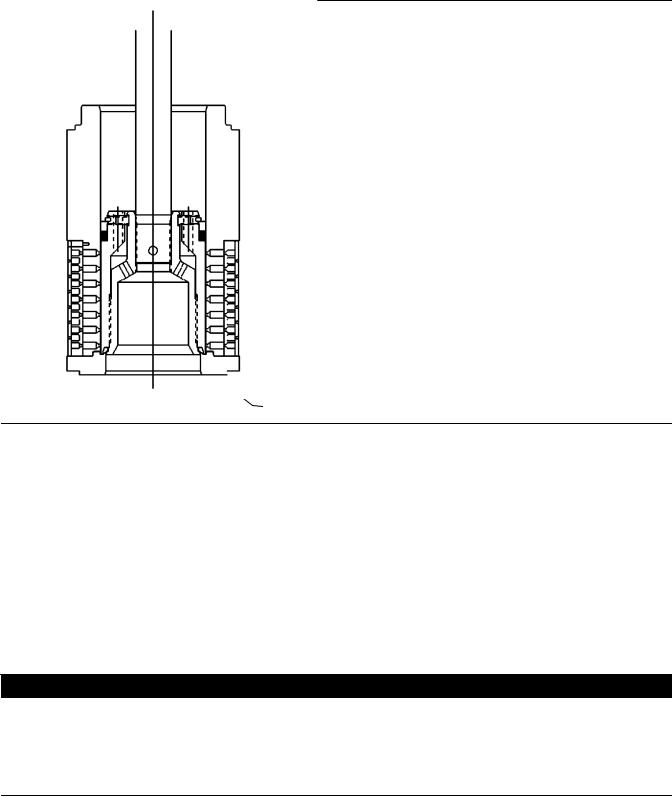
Figure 6. Detail of Protected Soft Seat
CAGE
A7088
TSO Trim
Refer to figure 7.
1.Remove the retainer, backup ring, anti-extrusion rings, and piston ring.
2.Remove the set screws that lock the outer plug to the inner plug.
3.Using a strap wrench or similar tool, unscrew the outer plug from the inner plug. Do not damage the outer plug guide surfaces.
4.Remove the protected soft seat seal (see figure 5).
5.Inspect the parts for damage and replace if needed.
6.Refer to the Valve Plug Maintenance procedure or to the Lapping Seats procedure.
14
Instruction Manual |
EH (1-1/2x1 through 8x6) |
D100394X012 |
December 2014 |
|
|
Figure 7. Typical Balanced TSO Trim
SEAL
SOFT SEAT
Valve Plug Maintenance
Key numbers used in this procedure are shown in figure 17 for the EHD valve, in figure 18 for the EHS valve, and in figure 20 for the EHT valve.
1. With the valve plug (key 3) removed according to the Trim Removal procedure, proceed as appropriate:
For the EHD valve, the piston rings (key 8) are each in two sections; remove the sections from the grooves in the valve plug.
For the EHS valve, proceed to step 2.
For the EHT valve, work the retaining ring (key 10) off the valve plug with a screwdriver. Carefully slide the backup ring and seal ring (keys 9 and 8) off the valve plug. For an NPS 6 valve with a level D Whisper Trim III cage, also remove the piston ring (key 30) from the grooves in the valve plug.
2. To replace the valve plug stem (key 4), drive out the pin (key 5), and unscrew the stem from the valve plug.
CAUTION
Never reuse an old stem with a new valve plug or reinstall a valve stem after it has been removed. Using an old stem with a new plug requires drilling a new pin hole in the stem. This weakens the stem and may cause the stem to fail in service. If a new valve plug is required, always order a valve plug, stem, and pin as an assembly. Specify the correct part number of each of the three parts, but state that the parts are being ordered as an assembly.
A used valve plug may be reused with a new stem. An exception is the Cavitrol III plug/stem assembly which must be ordered and replaced as a unit.
15

EH (1-1/2x1 through 8x6) |
Instruction Manual |
December 2014 |
D100394X012 |
|
|
3.Thread the new stem into the valve plug and tighten it to the appropriate torque value given in table 10. Using the valve plug pin hole as a guide, drill the pin hole through the stem. Refer to table 10 for drill sizes.
4.Drive in the pin to lock the assembly.
5.If it is necessary to lap the seating surfaces, complete the Lapping Seats procedure before installing the EHD piston rings or the EHT seal ring. The Trim Replacement procedure provides piston ring and seal ring installation instructions and valve reassembly instructions.
Lapping Seats
Key numbers referenced in this procedure are shown in figure 17 for the EHD valve, in figure 18 for the EHS valve, and in figure 20 for the EHT valve unless otherwise indicated.
Seating surfaces of the valve plug (key 3) and the seat ring (key 6) can be lapped for improved shutoff. Use a good quality lapping compound with a mixture that contains 280 to 600 grit. Apply the compound to the bottom of the valve plug. Use the following procedure to lap the seating surfaces.
1.Install the following parts according to the instructions presented in the Trim Replacement procedure: seat ring gasket or O-ring (key 12), seat ring (key 6), seat ring retainer (key 7), cage (key 2), cage gaskets (key 11), and if used, the O-ring (key 26, figure 21).
2.Proceed as appropriate:
For an EHD or EHT valve, install the valve plug and stem assembly (keys 3 and 4)–without piston rings or seal ring (keys 8 and 30)–into the cage.
For an EHS valve, install the valve plug and stem assembly (keys 3 and 4) into the cage.
3.Install the bonnet (key 1, figure 16) over the valve stem, and secure the bonnet with four of the hex nuts (key 14).
4.Attach a handle, such as a piece of strap iron secured by stem locknuts, to the valve stem. Rotate the handle alternately in each direction to lap the seats.
Note
To preserve the effects of lapping, do not change either the position of the seat ring in the valve body cavity or the position of the cage on the seat ring after lapping the seating surfaces. If possible, clean the parts without disturbing their positions. If the parts must be removed for cleaning, return them to the original positions.
5.After lapping, again disassemble as necessary, clean the seating surfaces, reassemble, and test for shutoff. Repeat the lapping procedure if necessary.
Trim Replacement
After all trim maintenance has been completed, reassemble the valve by following the numbered steps below. Be certain that all gasketed surfaces have been well cleaned. Key numbers referenced in this procedure are shown in figure 17 for the EHD valve, in figure 18 for the EHS valve, and in figure 20 for the EHT valve.
16
 Loading...