


Fisher Baumann 51000
51000 Valve
D103339X012
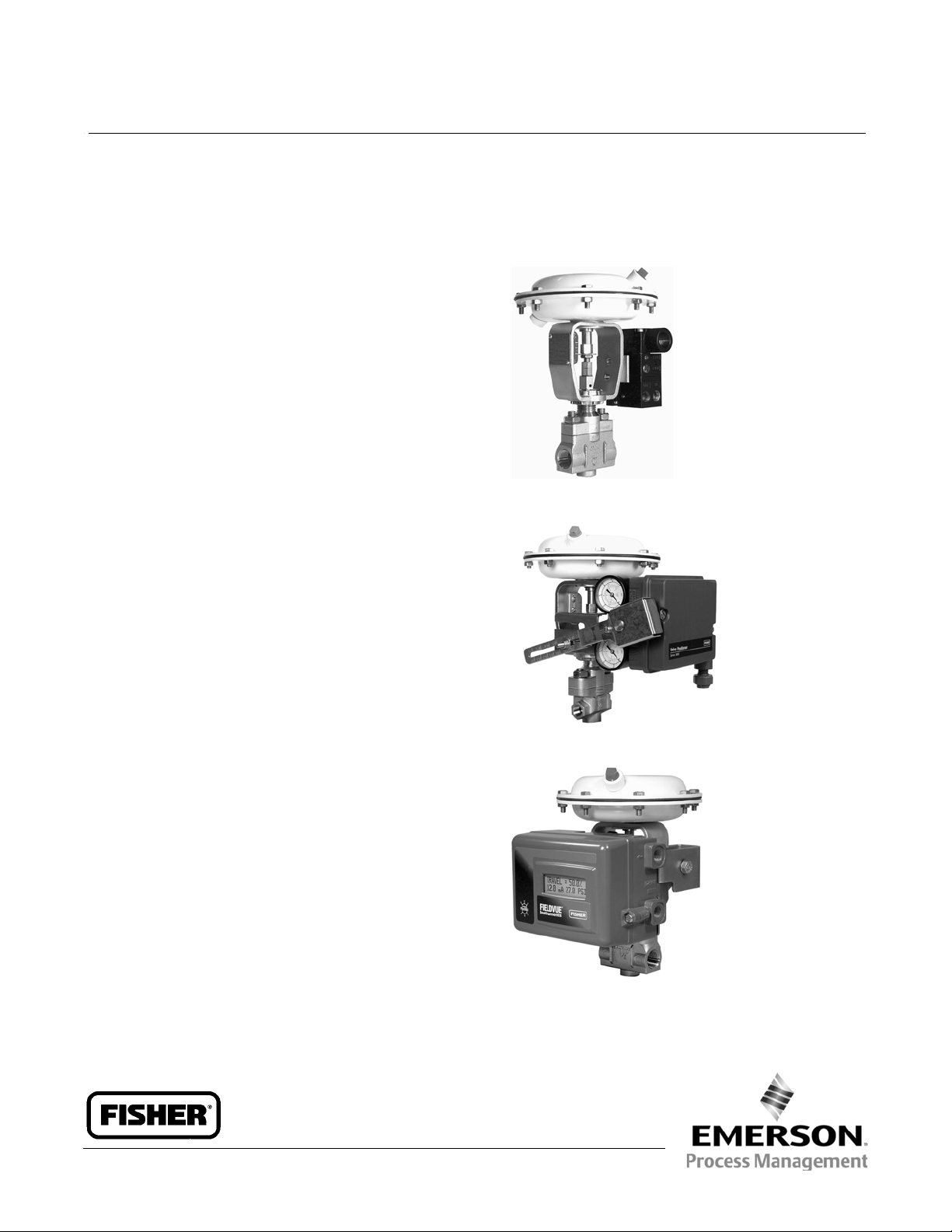
Baumannt 51000 High-Pressure,
Low-Flow Control Valve
The Baumann 51000 control valve is optimally
designed for demanding low-flow, high-pressure
control applications often found in laboratories and
pilot plants. NPS 1/4 or 1/2 valve assemblies are
standard as either investment cast stainless steel or
N10276 nickel alloy. Constructions with other high
nickel alloys are available.
With a small footprint, less than 10 inches tall, and
multiple trim capacity reductions available to meet
changing process requirements, the 51000 is a perfect
fit where space is at a premium and flexibility is a must.
The valve is suited for demanding control of gases,
chemical/dye injection and acid/caustic solutions in
paper production, textiles, specialty chemicals, and
many other industries.
W9733
Baumann 51000 NPS 1/2 Control Valve
with TA6000 Electropneumatic Transducer (I/P)
Product Bulletin
52.1:51LF
October 2014
Features
Compact Size.
Suitable for sticky fluids and corrosive atmospheres.
Quick Trim Change Out - Matched trims not
required.
Investment cast stainless steel body in NPS 1/4 and
1/2, or barstock N10276 Nickel Alloy. Other alloys
available.
Class VI shutoff with soft seat available.
Up to 207 barg (3000 psig) at 37_C(100_F).
Rugged bolted bonnet design.
Wide flow capacity range. Maximum rated Cv
ranges from 0.00013 to 2.5 (0.00011 to 2.16 Kv).
Corrosion-resistant actuator.
Available without positioner for fail-open or
fail-close applications.
W9734
51000 NPS 1/4 Control Valve with Baumann 16 Actuator,
and Fisherr 3660 Pneumatic Positioner
W9066
51000 NPS 1/2 Control Valve with Baumann 16 Actuator,
and FIELDVUEt DVC2000 Digital Valve Controller
www.Fisher.com
Product Bulletin
52.1:51LF
October 2014
51000 Valve
D103339X012
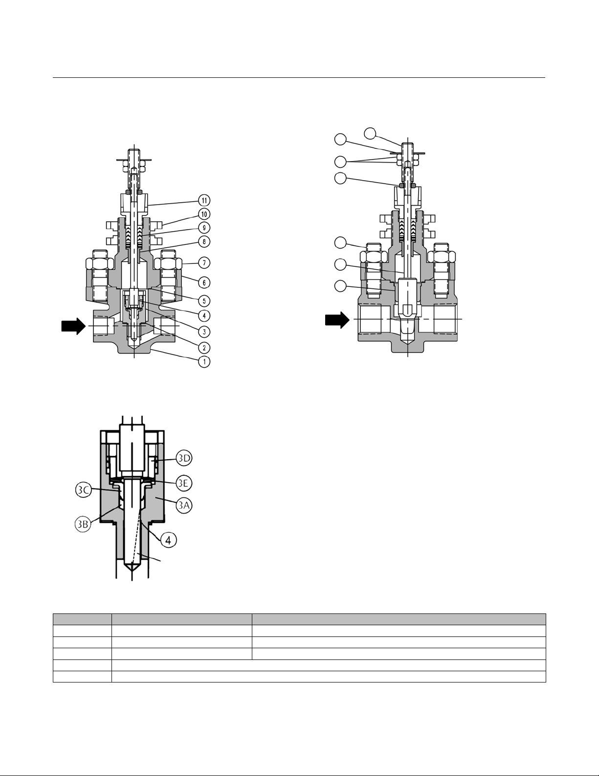
Figure 1. NPS 1/4 and 1/2 (6.35 and 12.7 mm) Soft
SeatCageDesignforCv=0.00013to0.45ClassVI
Shutoff (N10276 Nickel Alloy Construction Available)
FLOW
DOWN
E1230
Soft Seat
Figure 3. NPS 1/2 (12.7 mm) Integral (Metal) Seating
for Cv = 1.0, 1.5, and 2.5 Class IV Shutoff
58
27
31
28
32
33
FLOW
UP
E1232
26
Metal Seat
Figure 2. Soft Seat Cage Assembly
The PTFE ring (key 3B) surrounds the valve plug (key 4)
to help eliminate clearance flow typical of lapped-in
metal-to-metal close clearance micro trims. Flow is
directed over the valve plugandforcedthrougha
single V-notch path as the plug moves above the PTFE
ring, providing precise and predictable control over its
entire travel range. When the V-notch moves below
the PTFE ring, Class VI primary shutoff is achieved.
A live-loaded metal seat collar (key 3C) fully retains the
PTFE ring (key 3B). The valve plug (key 4) seats against
the metal collar providing Class IV secondary shutoff.
V-NOTCH
GROOVE
E1231
In addition, the fluid process pressure combines with
the actuator seating force to form a hydraulic seal
within the fully retained PTFE ring (key 3B). Therefore,
thehighertheprocesspressurethetightertheshutoff.
Table 1. Baumann 51000 Soft Seat Cage Assembly
Key Number Parts Material
3A Cage ASTM A276S31600 ConditionA or ASTM B574 N10276,35 HRC Max
3B Ring PTFE (Polytetrafluoroethylene)
3C Collar ASTM A276S31600 ConditionA or ASTM B574 N10276,35 HRC Max
3D Retainer
3E Spring
2
51000 Valve
D103339X012
Product Bulletin
52.1:51LF
October 2014
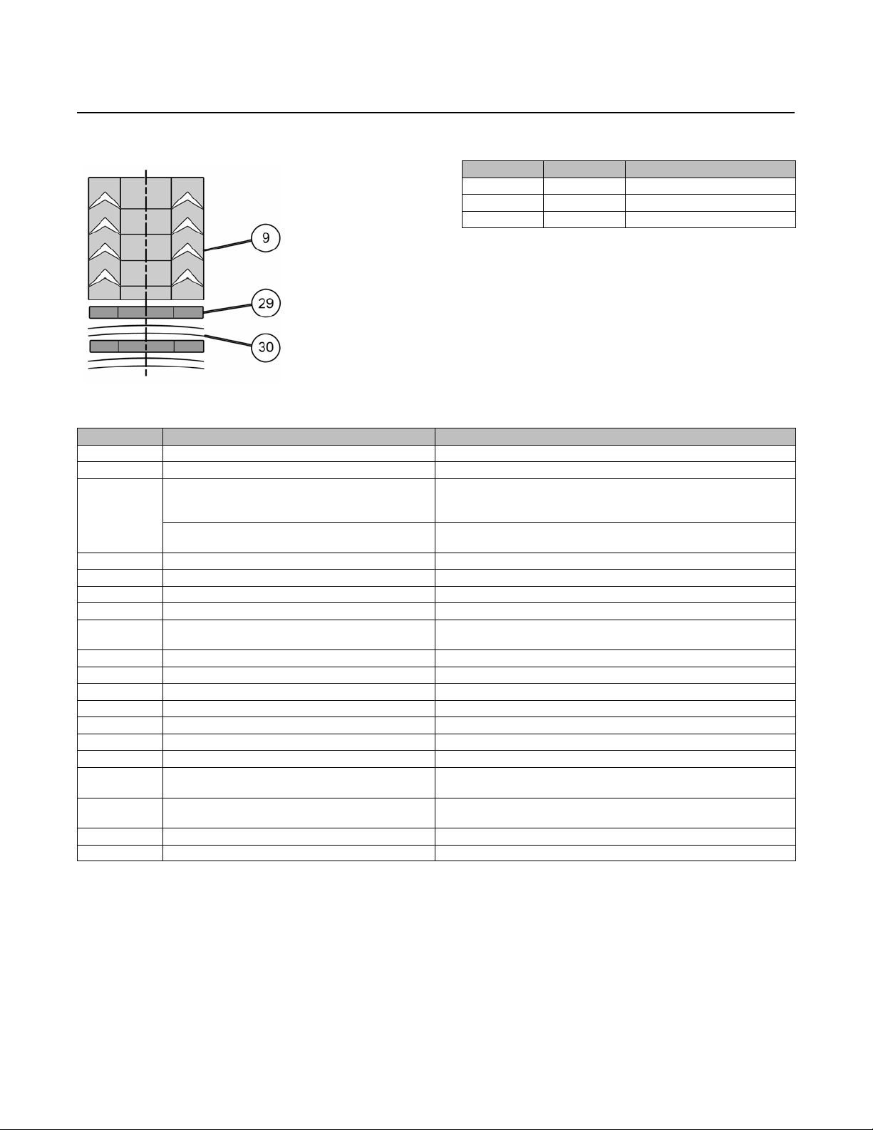
Figure 4. V-Ring Packing Kit
E1233
Table 2. Baumann 51000 V-Ring Packing Kit 51607
Key Number Quantity Description
9 1 Packing Set
29 2 Flat Washer
3 4 Disc Spring
Table 3. Materials of Construction
Key Number Parts Material
1 Valve Body, NPS 1/4 and NPS 1/2 ASTM A351CF8M or ASTM B575 N10276, 35 HRC Max
2 Seat Cage Gasket Reinforced Graphite
Soft Seat Cage Assy, (Cv's 0.00013 to 0.45),
3
4 Plug/Stem (Cv's 0.00013 - 0.45); (Kv's0.00011 to 0.39) ASTM A479 S21800 Annealed orASTM B574 N10276, 35 HRC Max
5 Bonnet Gasket Flexible Graphite and Polymer Composite
6 Bonnet ASTM A351CF8M or ASTM B574 N10276, 35 HRC Max
7 Hex Nuts 18-8 Stainless Steel
8 Stem Guide
9 V-Ring Packing Kit PTFE (Polytetrafluoroethylene) & S30400 & S30100
10 Clamp Nut ASTM A240 S30400
11 Packing Follower Nut ASTM A582S30300 ConditionA or ASTM B574 N10276, 35 HRC Max
26 Stem Adapter, Baumann 16 Actuator 18-8 Stainless Steel
27 Hex Jam Nut, Baumann 16 Actuator 18-8 Stainless Steel
28 Body Studs S30400 ASTMA193, B8 Class 1
31 Stem Adapter Nut 18-8 Stainless Steel
32
33 Plug Guide
34 Flange, Bonnet ASTM A743 CF8
35 Travel Indicator Disc, Baumann 16 Actuator 18-8 Stainless Steel
Seat, Body(Integral Seat) (Cv's 1.0, 1.5, 2.5); (Kv's 0.86,
Plug and Stem S/A (for metal seated plugs) Integral Seat,
Cv's 1.0,1.5, & 2.5; (Kv's 0.86, 1.29, 2.16)
Figure 1 ONLY!
(Kv's 0.00011 to 0.39)
1.29, 2.16)
Seefigure2,table1
ASTM A351CF8M or ASTM B575 N10276, 35 HRC Max
ASTM A582S30300 Condition A or
Carbon Fiber-Filled Thermoplastic Fluoropolymer
ASTM A276S31600 ConditionA or ASTM B574 N10276, 35 HRC Max
ASTM A479 S21800 Annealed or
Carbon Fiber-Filled Thermoplastic Fluoropolymer
3
Product Bulletin
52.1:51LF
October 2014
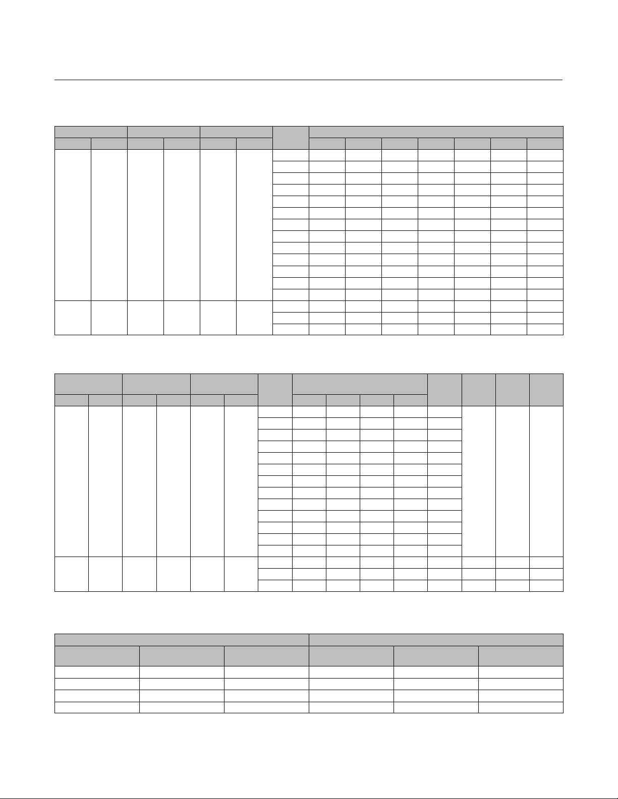
Table 4. Flow Coefficients (ASME/ISA/IEC)
Valve Size Orifice Diameter Plug Tvl
mm NPS mm in. mm in. 5 10 20 30 40 50 60
6.35
12.7
12.7 1/2 9.53 0.375 12.7 0.5
1/4
1/2
3.97 0.156 12.7 0.5
Trim
No.
16 0.000001 0.000003 0.00001 0.00002 0.00003 0.00005 0.00006
15 0.000002 0.000006 0.00002 0.00004 0.00006 0.00009 0.00011
14 0.000004 0.000014 0.00004 0.00006 0.00009 0.00013 0.00021
13 0.00001 0.00003 0.00008 0.00012 0.00017 0.00025 0.00037
12 0.00002 0.00007 0.00017 0.00025 0.00036 0.0005 0.0007
11 0.00004 0.0001 0.00025 0.00040 0.00058 0.0009 0.0014
10 0.00008 0.00015 0.00030 0.00057 0.0010 0.0017 0.0029
09 0.00009 0.00018 0.00040 0.0008 0.0016 0.0031 0.0057
08 0.00010 0.00020 0.0005 0.0012 0.0028 0.006 0.010
07 0.00012 0.00025 0.0007 0.0019 0.005 0.011 0.022
06 0.00015 0.0003 0.001 0.003 0.008 0.021 0.040
05 0.0002 0.0005 0.002 0.006 0.016 0.04 0.079
04 0.0017 0.005 0.011 0.02 0.034 0.06 0.11
03 0.009 0.014 0.030 0.06 0.11 0.17 0.25
02 0.015 0.020 0.050 0.10 0.15 0.25 0.37
01 0.023 0.035 0.075 0.15 0.25 0.42 0.61
CVAT VALVE OPENING - Percent of Plug Travel
51000 Valve
D103339X012
Table 5. Flow Coefficients (ASME/ISA/IEC) (continued)
Valve Size Orifice Diameter Plug Tvl
mm NPS mm in. mm in. 70 80 90 100
6.35
12.7
12.7 1/2 9.53 0.375 12.7 0.5
1/4
1/2
3.97 0.156 12.7 0.5
Trim
No.
16 0.00008 0.0001 0.0012 0.00013 0.035
15 0.00015 0.0002 0.00023 0.00025 0.04
14 0.00031 0.0004 0.00045 0.0005 0.05
13 0.0006 0.0008 0.0009 0.001 0.06
12 0.0010 0.0015 0.0018 0.002 0.075
11 0.0020 0.0029 0.0036 0.004 0.10
10 0.0046 0.0062 0.0072 0.008 0.11
09 0.0087 0.011 0.014 0.015 0.15
08 0.016 0.022 0.026 0.03 0.18
07 0.035 0.046 0.054 0.06 0.22
06 0.062 0.08 0.09 0.10 0.25
05 0.12 0.16 0.18 0.20 0.3
04 0.19 0.29 0.38 0.45 0.4
03 0.35 0.45 0.60 1.0 0.23 0.95 0.75 0.86
02 0.50 0.72 1.2 1.5 0.31 0.90 0.68 0.73
01 0.88 1.2 1.7 2.5 0.60 0.88 0.65 0.68
CVAT VALVE OPENING - Perc ent of
Plug Travel
F
d
F
L
0.98 0.80 0.94
Table 6. Valve Body S/A Pressure-Temperature Ratings
WORKING PRESSURE (barg) WORKING PRESSURE (psig)
Temperature (_C) ASTM A351 CF8M
-195 to37.8 207 207 -320 to 100 3000 3000
93.3 178 207 200 2580 3000
149 161 207 300 2330 3000
176 154 207 350 2235 3000
ASTM B575 N10276,
35 HRC Max
Temperature (_F) ASTM A351 CF8M
X
ASTM B575 N10276,
35 HRC Max
K
T
C
4
 Loading...