


Instruction Manual |
D2 FloPro Valve |
D103031X012 |
June 2011 |
Fisherr D2 FloPro Control Valve |
|
Contents |
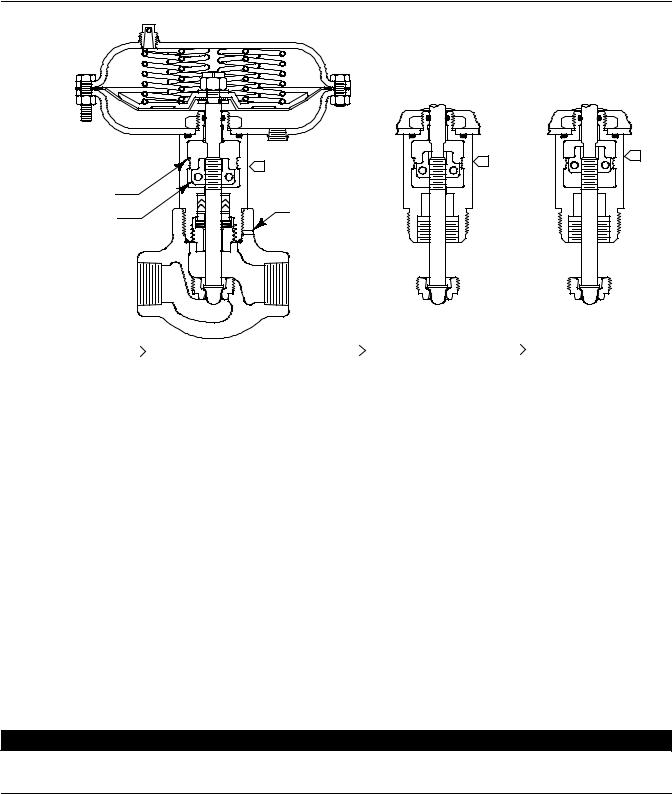
Figure 1. Fisher D2 FloPro Control Valve |
Introduction . . . . . . . . . . . . . . . . . . . . . . . . . . . . . . . . |
. 1 |
Scope of Manual . . . . . . . . . . . . . . . . . . . . . . . . . . . . . |
1 |
Description . . . . . . . . . . . . . . . . . . . . . . . . . . . . . . . . . |
1 |
Specifications . . . . . . . . . . . . . . . . . . . . . . . . . . . . . . . |
2 |
Installation . . . . . . . . . . . . . . . . . . . . . . . . . . . . . . . . . . |
3 |
Setting Valve FloPro Flow Adjuster . . . . . . . . . . . . . . |
4 |
Changing Actuator Action from |
|
(Air-to-Open) to (Air-to-Close) . . . . . . . . . . . . . . . |
4 |
Maintenance . . . . . . . . . . . . . . . . . . . . . . . . . . . . . . . . . |
5 |
Valve Trim Maintenance . . . . . . . . . . . . . . . . . . . . . . |
6 |
Packing, Valve Trim, and |
|
Actuator Maintenance . . . . . . . . . . . . . . . . . . . . . |
7 |
Parts Kits . . . . . . . . . . . . . . . . . . . . . . . . . . . . . . . . . . . |
14 |
Parts List . . . . . . . . . . . . . . . . . . . . . . . . . . . . . . . . . . . |
14 |
Appendix A (Packing Constructions |
|
with Lot Numbers Less Than 0410-xxxx) . . . . . . . . . |
17 |
W9235-1
Introduction
Scope of Manual
This instruction manual provides installation, maintenance, and parts information for the NPS 1 Fisher D2 FloPro control valve and actuator manufactured with lot numbers equal to and greater than 0410-xxxx.
See Appendix A for information on packing constructions manufactured with lot numbers less than 0410-xxxx.
Do not install, operate, or maintain a D2 FloPro control valve without being fully trained and qualified in valve, actuator, and accessory installation, operation, and maintenance. To avoid personal injury or property damage, it is important to carefully read, understand, and follow all the contents of this manual, including all safety cautions and warnings. If you have any questions about these instructions, contact your Emerson Process Management sales office before proceeding.
Description
The D2 FloPro control valve (figure 1) is a compact, rugged valve designed for on-off control of a variety of fluids at pressures up to 155 bar (2250 psig). This valve is ideal for use as a dump valve on gas separators and scrubbers. It is also well suited for other high pressure applications in natural gas production, compression, and processing. The D2 FloPro valve has threaded end connections and is available in an NPS 1 globe style valve body.
www.Fisher.com

D2 FloPro Valve |
Instruction Manual |
June 2011 |
D103031X012 |
|
|
Table 1. Specifications
Valve Assembly Pressure Class
ASME B16.34 CL900
Maximum Inlet Pressure and Temperature(1)
155 bar from -46 to 93 C, and 150 bar at 149 C. (2250 psig from —50 to 200 F, and 2185 psig at 300 F)
Maximum Allowable Pressure Drop(1)
Flow Down(2)
Maximum Inlet Pressure: 155 bar (2250 psig) Maximum Outlet Pressure: 103 bar (1500 psig)
Flow Up
Maximum Inlet Pressure: 103 bar (1500 psig) Maximum Outlet Pressure: 103 bar (1500 psig)
Shutoff Classification
Class IV ANSI/FCI 70-2 and IEC 60534-4
Construction Materials
Valve Body and Bonnet: ASME SA 352 LCC Valve Plug and Seat: J R30006 (Alloy 6) or J S17400 double H1150
Valve Stem: S31600
O-Rings: HNBR (Hydrogenated Nitrile) Packing: PTFE/Carbon PTFE
Packing Springs: N07718
Stem Bushing: PPS (polyphenylene sulfide) Actuator Diaphragm: Nitrile/Polyester Actuator Springs: Zinc-plated steel
Flow Characteristic
FloPro Characterized
Port Diameter
13 mm (0.5 inch)
Maximum Travel
13 mm (0.5 inch)
Approximate Weight
7.7 kg (17 lb)
Material Temperature Capabilities
Valve Body Assembly: -46 to 149 C (-50 to 300 F) Actuator Assembly: -46 to 93 C (-50 to 200 F)
Bonnet/Body Connection
Threaded with leakoff bleed
Standard Actuator Configuration
The D2 FloPro actuator is an on-off spring-and-diaphragm.
Globe Valve Body: Supplied as either Air-to-Open or Air-to-Close.
Maximum Actuator Casing Pressure
2.8 bar (40 psig)
Minimum Required Actuator Casing Pressure
2.1 to 2.4 bar (30 to 35 psig)
Actuator Diaphragm Effective Area
194 cm2 (30 square inches)
Actuator Pressure Connections
1/4 NPT internal
1.The pressure or temperature limits in the referenced tables and any applicable ASME code limitations should not be exceeded.
2.Standard flow direction.
Specifications
Table 1 lists specifications for the D2 FloPro control valve. Some of the specifications for a given control valve as it originally comes from the factory are stamped on a nameplate located on the upper diaphragm casing flange.
2

Instruction Manual |
D2 FloPro Valve |
D103031X012 |
June 2011 |
|
|
Installation

 WARNING
Always wear protective gloves, clothing, and eyewear when performing any installation operations to avoid personal injury.
Personal injury or equipment damage caused by sudden release of pressure may result if the valve assembly is installed where service conditions could exceed the limits given in table 1 or on the appropriate nameplates. To avoid such injury or damage, provide a relief valve for overpressure protection as required by accepted industry or local, state, and Federal codes and good engineering practices.
Check with your process or safety engineer for any additional measures that must be taken to protect against process media.
If installing into an existing application, also refer to the WARNING at the beginning of the Maintenance section in this instruction manual.
CAUTION
This valve is intended for a specific range of pressures, temperatures, and other service conditions (see table 1). Applying different pressure, temperature, and other conditions to the valve could result in parts damage, malfunction of the valve, or loss of control of the process. Do not expose this valve to service conditions or variables other than those for which this valve is intended. If you are not sure what these conditions are, you should contact your Emerson Process Management sales office for more complete specifications.
1.Before installing the valve, inspect it to be certain that the valve body cavity is free of foreign material. Clean out all pipelines to remove scale, welding slag, and other foreign materials.
2.The control valve assembly may be installed in any orientation unless limited by seismic criteria.
The standard flow direction is indicated by the arrow on the valve body.
3.Use accepted piping practices when installing the valve in the pipeline.
4.If continuous operation is required during inspection or maintenance, install a three-valve bypass around the control valve assembly.
Note
The NPS 1 D2 FloPro valve is equipped with ENVIRO-SEALt D2 packing.
The actuator is available from the factory as either air-to-open or air-to-close.
Additionally, the actuator as shipped from the factory, has the FloPro flow adjuster set at a 0.375 inch port flow rate position. If some other flow rate is desired, see the Setting Valve FloPro Flow Adjuster section in this manual.
3
D2 FloPro Valve |
Instruction Manual |
June 2011 |
D103031X012 |
|
|
Figure 2. Flow Rate Adjustments
|
|
2 |
3 |
|
1 |
|
|
|
|
|
|
FloPro TRAVEL |
|
|
|
INDICATOR |
|
|
|
FLOW ADJUSTER |
|
SAFETY |
|
|
VENT |
|
|
|
|
|
|
|
0.5 INCH FLOW RATE |
2 |
0.375 INCH FLOW RATE |
3 |
0.25 INCH FLOW RATE |
|
1 |
|||||
|
|
Cv = 6 |
|
Cv = 4 |
|
Cv = 2 |
|
|
Fl = 0.77 |
|
Fl = 0.706 |
|
Fl = 0.65 |
GE15452 |
|
Xt = 0.476 |
|
Xt = 0.319 |
|
Xt = 0.245 |
|
|
|
|
|
|
|
Setting Valve FloPro Flow Adjuster
Air-to-Open Actuator Action
1.To change the valve flow rate, loosen the flow adjuster socket head cap screws (key 29), and reposition the flow adjuster halves (key 14 and 15) to the desired flow rate position. See figure 2 for flow rate settings.
Air-to-Close Actuator Action
1.Attach a pressure line to the actuator. Supply pressure to the actuator to seat the plug in the seat ring.
2.To change the valve flow rate, loosen the flow adjuster socket head cap screws (key 29), and reposition the flow adjuster halves (key 14 and 15) to the desired flow rate position. See figure 2 for flow rate settings.
Changing Actuator Action from (Air-to-Open) to (Air-to-Close)
Key numbers are referenced in figures 6 and 7.

 WARNING
To prevent possible personal injury or property damage from removing the casing cap screws in the wrong sequence, follow the procedure as outlined below for removing the upper casing.
4

Instruction Manual |
D2 FloPro Valve |
D103031X012 |
June 2011 |
|
|
1.Remove the six short actuator casing cap screws (key 22) first. Once these have been removed from the actuator assembly, remove the two long actuator cap screws (key 30) by alternating between them as you loosen them, to keep the upper casing (key 21) level during this procedure.
Note
Be aware as you loosen and remove the actuator cap screws that the actuator springs are under compression.
2.Remove the upper casing (key 21) and the springs (key 27).
3.Do not turn the valve stem (key 4) while removing the diaphragm hex nut (key 26). Keep the stem from turning by using an open end wrench on the machined flats located on the valve stem above the flow adjuster for this procedure. Continue the actuator disassembly by removing the washer (key 24) diaphragm plate (key 25), diaphragm (key 19), washer (key 36), and O-ring (key 37). Inspect the diaphragm for any wear or damage. Replace with a new one if necessary.
4.Unscrew the socket head cap screws (key 29), and remove the flow adjuster halves (key 14 and 15). Position the stem (key 4) to its most upward position.
5.Place 2 of the springs (key 27) from the actuator into the bottom casing (key 20), equally spaced, 180 degrees apart. Place the washer (key 36) over the valve stem, as shown in view A of figure 7. Then place the O-ring (key 37) over the valve stem. Next install the diaphragm plate (key 25) and, using the diaphragm plate, correctly position the actuator springs.
6.Place the diaphragm (key 19) over the stem, along with washer (key 24). Position the diaphragm so the holes in the diaphragm align with the holes in the bottom casing.
7.Insert a 1/8 inch diameter drift punch, or other suitable device through the 5/32 inch diameter hole in the valve stem located below the bottom of the previously removed flow adjuster. Install hex nut (key 26) and tighten to 10 NSm (90 lbfSin). Use the 1/8 inch drift punch or other holding device to turn the stem to align the holes of the diaphragm (key 19) to the lower casing (key 20).
8.Position the upper casing and install the two long cap screws (key 30) opposite one another. Install the six shorter cap screws (key 22) and the hex nuts, tightening the actuator casing cap screws evenly using a cross-tightening procedure. Torque to 10 NSm (8 lbfSft).
9.Connect a pressure line to the top actuator pressure connection, and apply pressure to the actuator. Stroke the actuator until the valve plug is seated on the seat ring. Install the flow adjuster, positioning it to the desired travel. Tighten the flow adjuster socket head cap screws to 3 NSm (26 lbfSin).
10.Release the actuator pressure, and install the vent plug (key 28) into the bottom casing pressure connection.
Maintenance
Valve parts are subject to normal wear and must be inspected and replaced as necessary. Inspection and maintenance frequency depends on the severity of service conditions. This section includes instructions for packing and trim maintenance, and replacing actuator parts.
All maintenance operations can be performed with the valve in the line.
Note
Whenever a gasket seal or O-ring is disturbed by removing or shifting gasketed parts, a new gasket should be installed upon reassembly. This is necessary to ensure a good gasket seal, since the used gasket or O-ring will not seal properly.
5

D2 FloPro Valve |
Instruction Manual |
June 2011 |
D103031X012 |
|
|

 WARNING
Avoid personal injury from sudden release of process pressure. Before performing any maintenance operations: D Do not remove the actuator from the valve while the valve is still pressurized.
DAlways wear protective gloves, clothing, and eyewear when performing any maintenance operations to avoid personal injury.
DDisconnect any operating lines providing air pressure or a control signal to the actuator. Be sure the actuator cannot suddenly open or close the valve.
DUse bypass valves or completely shut off the process to isolate the valve from process pressure. Relieve process pressure on both sides of the valve. Drain the process media from both sides of the valve.
D Use lock-out procedures to be sure that the above measures stay in effect while you work on the equipment.
DThe valve packing box may contain process fluids that are pressurized, even when the valve has been removed from the pipeline. Process fluids may spray out under pressure when removing the packing hardware or packing rings.
DCheck with your process or safety engineer for any additional measures that must be taken to protect against process media.
Valve Trim Maintenance
Note
The following maintenance procedures apply to both air-to-open and air-to-close actuator configurations, except for steps 2. and 8. as noted.
Key numbers are referenced in figures 6 and 7.
1.Isolate the control valve from the line pressure, release pressure from both sides of the valve body, and drain the process media from both sides of the valve.
2.For air-to-open actuator action only, apply pressure to the actuator to fully stroke it open. This will raise the plug off its seat so that the valve stem serrations are visible inside the flow adjuster window (see figure 3). Loosen the socket head screws (key 29) and lower the flow adjuster (key 14 and 15) to its lowest position on the valve stem. Retighten the socket head screws (key 29) to 3 NSm (26 lbfSin). Relieve pressure to the actuator, shut off all pressure lines to the actuator, and disconnect. Use lockout procedures to be sure that the above measures stay in effect while you work on the equipment.
CAUTION
The preceding step is intended to prevent damage to the valve plug (key 3) and seat ring (key 5) during the removal of the bonnet and actuator.
3. Unscrew the bonnet from the valve body.
6

Instruction Manual |
D2 FloPro Valve |
D103031X012 |
June 2011 |
|
|

 WARNING
Avoid personal injury from sudden release of process pressure. If the process media starts to escape from the safety vent (see figure 2) located in the bonnet neck of the valve body,
STOP DISASSEMBLY IMMEDIATELY!
The escape of process media indicates that the valve has NOT been isolated from the process media, or process pressure is trapped in the valve body.
Check with your process or safety engineer for any additional measures that must be taken to protect against process media.
4.Once the bonnet has been removed from the valve body, inspect the seat ring (key 5) for wear or damage. If the seating surface has been damaged, remove it from the valve body. Also remove the seat ring gasket (key 6). Clean and inspect the valve body gasket surface for damage. Visually inspect the valve body interior below the seat ring for erosion. Replace the valve body if necessary.
To replace the seat ring, first install a new seat ring gasket. Install the new seat ring and tighten to 230 NSm (170 lbfSft).
Cover the opening in the valve body to prevent foreign material from getting into the valve body cavity.
5.Inspect the valve stem for scratches or wear, and valve plug for wear or damage. Replace if necessary.
6.If the valve plug requires replacement, use an open end wrench on the machined flats located on the valve stem above the flow adjuster and unscrew the valve plug from the valve stem. Replace it with a new valve plug. Screw the valve plug into the valve stem, being careful not to damage the plug seat or plug contour. Tighten to 18 NSm (13 lbfSft).

 WARNING
Upon reassembly, ensure that no foreign material blocks the safety vent hole as shown in figure 2. If the safety vent hole is blocked or plugged, possible personal injury from the sudden release of process pressure during maintenance disassembly may occur.
7.Lubricate a new O-ring (key 13) with lithium grease and place it into the valve body as shown in figure 6 or 7. Ensure that no foreign material blocks the safety vent hole. Screw the bonnet into the valve body, and torque to a range of 542 to 678 NSm (400 to 500 lbfSft).
8.For air-to-open actuator action only, attach the pressure line to the actuator, and supply pressure to the actuator. Loosen the socket head screws (key 29) and remove the flow adjuster (keys 14 and 15). Release the pressure to the actuator. This allows the plug to find its seated position.
9.Set the flow adjuster to the desired travel position (see figure 2), and tighten the flow adjuster socket head cap screws to 3 NSm (26 lbfSin).
Packing, Valve Trim, and Actuator Maintenance
Note
The following maintenance procedures apply to both air-to-open and air-to-close actuator configurations, except as noted.
7

D2 FloPro Valve |
Instruction Manual |
June 2011 |
D103031X012 |
|
|
Figure 3. Fisher D2 FloPro Construction
PRESSURE
CONNECTION
VALVE STEM SERRATIONS
VISIBLE IN THE FLOW
ADJUSTER WINDOW
W9005-1
GLOBE STYLE AIR-TO-OPEN
Key numbers are referenced in figures 6 and 7.
Disassembly
1.Isolate the control valve from the line pressure, release pressure from both sides of the valve body, and drain the process media from both sides of the valve.
2.For air-to-open actuator action only, apply pressure to the actuator to fully stroke it open. This will raise the plug off its seat so that the valve stem serrations are visible inside the flow adjuster window (see figure 3). Loosen the socket head screws (key 29) and lower the flow adjuster (key 14 and 15) to its lowest position on the valve stem. Retighten the socket head screws (key 29) to 3 NSm (26 lbfSin). Relieve pressure to the actuator, shut off all pressure lines to actuator, and disconnect. Use lockout procedures to be sure that the above measures stay in effect while you work on the equipment.
8
 Loading...