


Instruction Manual |
2052 Actuator |
D103296X012 |
November 2011 |
|
|
Fisherr 2052 Diaphragm Rotary Actuator
Contents |
|
Introduction . . . . . . . . . . . . . . . . . . . . . . . . . . . . . . . . |
. 1 |
Scope of Manual . . . . . . . . . . . . . . . . . . . . . . . . . . . . . |
1 |
Description . . . . . . . . . . . . . . . . . . . . . . . . . . . . . . . . . |
1 |
Specifications . . . . . . . . . . . . . . . . . . . . . . . . . . . . . . . |
3 |
Installation . . . . . . . . . . . . . . . . . . . . . . . . . . . . . . . . . . |
4 |
Actuator Mounting . . . . . . . . . . . . . . . . . . . . . . . . . . |
5 |
Maintenance . . . . . . . . . . . . . . . . . . . . . . . . . . . . . . . . . |
7 |
Replacing Diaphragm . . . . . . . . . . . . . . . . . . . . . . . . |
8 |
Replacing Diaphragm Plate, |
|
Diaphragm Rod Assembly, and Spring(s) . . . . . . |
9 |
Changing Or Replacing Actuator Lever . . . . . . . . . |
11 |
Positioner Mounting (3610 or DVC6020) . . . . . . . |
12 |
Top-Mounted Handwheel . . . . . . . . . . . . . . . . . . . . |
12 |
Locking Mechanism . . . . . . . . . . . . . . . . . . . . . . . . . |
13 |
Parts Ordering . . . . . . . . . . . . . . . . . . . . . . . . . . . . . . . |
17 |
Parts List . . . . . . . . . . . . . . . . . . . . . . . . . . . . . . . . . . . |
17 |
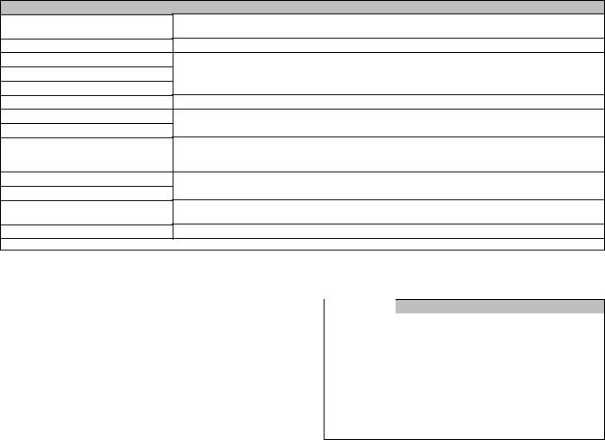
Figure 1. Fisher Control-Disk™ Valve with
2052 Actuator and DVC6200 Digital Valve Controller
W9425-2
Introduction
Scope of Manual
This instruction manual includes installation, adjustment, operation, maintenance, and parts information for the Fisher 2052 diaphragm rotary actuator (figure 1). Instructions for the control valve, positioner, manual actuator, and other accessories are included in separate manuals.
Do not install, operate, or maintain a 2052 actuator without being fully trained and qualified in valve, actuator, and accessory installation, operation and maintenance. To avoid personal injury or property damage, it is important to carefully read, understand, and follow all the contents of this manual, including all safety cautions and warnings. If you have any questions about these instructions, contact your Emerson Process Management sales office before proceeding.
Description
2052 spring-and-diaphragm rotary actuators are used on rotary-shaft valve bodies for throttling or on-off applications. The 2052 may be used for on-off service without a positioner, or it may be used for throttling service with a positioner, depending on service conditions. The 2052 has an ISO 5211 mating interface that allows installation to non-Fisher valves. Refer to separate bulletins for valve and positioner information.
www.Fisher.com
2052 Actuator |
Instruction Manual |
November 2011 |
D103296X012 |
|
|
A top-mounted handwheel option is available for infrequent service as a manual actuator. For repeated or daily manual operation, the unit should be equipped with a side-mounted declutchable 1078 manual actuator. Externally adjustable travel stops are used to limit the degree of rotation at both ends of the actuator stroke.
The lever for the 2052 actuator is supported by bushings. The lever may be changed to accommodate valve bodies with different size valve shafts.
Table 1. Fisher 2052 Actuator Specifications
Actuator Mounting Connections
Actuator Sizes
Operating Pressure(1)
Maximum Diaphragm Casing Pressure
Pressure Connection
Torque Output
Actuator Temperature Capabilities(1)
Operation
Approximate Weight
Controller/Positioners Available
Accessories Available
Handwheel
Operational Lockout
Specifications
Splined shaft connection, ISO 5211 actuator-to-bracket connection Size 1: F07, Size 2: F10, Size 3: F14
See table 2 See table 3
Size 1, 2, and 3 Actuators: 5 barg (73 psig) See table 4
See table 3
-45 to 80_C (-50 to 176_F)
Field reversible between PDTC and PDTO; rightand left-hand mounting, any angle of orientation
Size 1: 22.2 kg (49 lb) Size 2: 54.4 kg (120 lb) Size 3: 113 kg (250 lb)
DVC2000, DVC6020, DVC6030, DVC6200, 3610J, 3620J, 4190, C1 846, 646, 2625, and 67C Series, switches, i2P-100, VBL, DXP, GO™
Top-mounted handwheel: Optional on Size 1 and 2 actuators only Declutchable handwheel: Optional on Size 1, 2, and 3 actuators
Available for customer-supplied padlock to lock the actuator in the spring-fail position
1. The pressure/temperature limits in this manual should not be exceeded.
Table 2. Actuator and Shaft Size Availability
SHAFT SIZE |
|
ACTUATOR SIZE |
|
Inches |
1 |
2 |
3 |
1/2 |
available |
not available |
not available |
|
|
|
|
5/8 |
available |
available |
not available |
|
|
|
|
3/4 |
available |
available |
available |
|
|
|
|
1 |
not available |
available |
available |
|
|
|
|
1-1/4 |
not available |
available |
available |
|
|
|
|
1-1/2 |
not available |
not available |
available |
|
|
|
|
1-3/4 |
not available |
not available |
available |
|
|
|
|
2 |
not available |
not available |
available |
|
|
|
|
Table 4. Pressure Connections
ACTUATOR |
|
PRESSURE CONNECTION |
|
||
SIZE |
1/4 NPT |
1/2 NPT |
3/4 NPT |
G 1/4 |
|
1 |
standard |
optional |
not |
optional |
|
available |
|||||
|
|
|
|
||
|
|
|
|
|
|
2 |
standard |
optional |
not |
optional |
|
available |
|||||
|
|
|
|
||
|
|
|
|
|
|
3 |
not |
standard |
optional |
not |
|
available |
available |
||||
|
|
|
|||
|
|
|
|
|
|
Table 3. Torque versus Actuator Size
|
|
|
OPERATING PRESSURE |
|
|
||
ACTUATOR |
2 barg (29 psig)(1) |
4 barg (58 psig)(2) |
|
||||
SIZE AND |
|
|
|
|
|
|
|
|
Torque |
Torque |
|
|
|||
ACTION |
|
|
|
||||
|
NSm |
|
lbfSin |
NSm |
|
lbfSin |
|
1 (PDTO, PDTC) |
25.5 |
|
226 |
51.2 |
|
453 |
|
|
|
|
|
|
|
|
|
2 (PDTO, PDTC) |
105 |
|
930 |
210 |
|
1860 |
|
|
|
|
|
|
|
|
|
3 (PDTO) |
327 |
|
2890 |
631 |
|
5583 |
|
|
|
|
|
|
|
|
|
3 (PDTC) |
280 |
|
2479 |
584 |
|
5173 |
|
|
|
|
|
|
|
|
|
1. Operating pressure up to 3 barg (44 psig) is allowable for single spring construc tion.
2. Operating pressure up to 5 barg (73 psig) is allowable for dual spring construction.
2
Instruction Manual |
|
|
|
|
|
|
|
|
|
|
|
|
|
|
|
|
|
|
|
|
|
|
|
|
|
|
|
|
|
|
|
|
|
|
|
|
|
|
|
|
|
2052 Actuator |
||||||||||||||||||||||||||||||||||
D103296X012 |
|
|
|
|
|
|
|
|
|
|
|
|
|
|
|
|
|
|
|
|
|
|
|
|
|
|
|
|
|
|
|
|
|
|
|
|
|
|
|
|
|
|
|
|
|
|
|
|
|
|
|
|
|
|
|
|
|
|
|
|
|
|
|
|
|
|
|
November 2011 |
||||||||
|
|
|
|
|
|
|
|
|
|
|
|
|
|
|
|
|
|
|
|
|
|
|
|
|
|
|
|
|
|
|
|
|
|
|
|
|
|
|
|
|
|
|
|
|
|
|
|
|
|
|
|
|
|
|
|
|
|
|
|
|
|
|
|
|
|
|
|
|
|
|
|
|
|
|
|
|
Table 5. Fisher 2052 Actuator Mounting Styles |
|
|
|
|
|
|
|
|
|
|
|
|
|
|
|
|
|
|
|
|
|
|
|
|
|
|
|
|
|
|
|
|
|
|
|
|
|
|
|
|
|
|
|
|
||||||||||||||||||||||||||||||||
|
|
|
|
|
|
|
|
|
|
|
|
|
|
|
|
|
|
|
|
|
|
|
|
|
|
|
|
|
|
|
|
|
|
|
|
|
|
|
|
|
|
|
|
|
|
|
|
|
|
|
|
|
|
|
|
|
|
|
|
|
|
|
|
|
|
|
|
|
|
|
|
|
|
|
|
|
|
|
|
|
|
|
|
|
|
|
|
|
|
|
|
|
|
|
|
|
|
|
|
|
|
|
|
|
|
|
|
|
|
VALVE SERIES OR DESIGN |
|
|
|
|
|
|
|
|
|
|
|
|
|
|
|
VALVE SERIES OR DESIGN |
|||||||||||||||||||||||||||
|
|
|
|
|
|
|
|
|
|
|
|
|
|
|
|
|
|
|
|
|
|
|
|
|
|
|
|
|
|
|
|
|
|
|
|
|
|
|
|
|
|
|
|
|
|
|
|
|
|
|
|
|
|
|
|
|
|
|
|
|
|
|
|
|
|
|
|
|
|
|
A11, 8510B, 8532, |
|||||
MOUNTING |
|
|
|
|
|
|
ACTION(1) |
BALL/PLUG |
|
|
CV500 |
|
|
|
|
|
|
|
|
|
DISK/BALL |
8560, 8580, |
||||||||||||||||||||||||||||||||||||||||||||||||||||||
|
|
|
|
|
|
|
V150, V200 & V300 |
|
|
|
|
|
|
|
|
|
|
|
|
|
|
|
9500, and |
|||||||||||||||||||||||||||||||||||||||||||||||||||||
|
|
|
|
|
|
|
|
|
|
|
|
|
|
|
|
|
|
|
|
|
|
|
|
|
|
|
|
|
|
ROTATION TO |
|
|
V500 |
|
|
|
|
|
|
|
ROTATION TO |
|
|
|
|
|
|
|||||||||||||||||||||||||||||
|
|
|
|
|
|
|
|
|
|
|
|
|
|
|
|
|
|
|
|
|
|
|
|
|
|
|
|
|
|
|
|
CLOSE |
|
|
|
|
|
|
|
|
|
|
|
|
|
CLOSE |
|
|
|
|
|
|
Control-Disk |
|||||||||||||||||||||||
|
|
|
|
|
|
|
|
|
|
|
|
|
|
|
|
|
|
|
|
|
|
|
|
|
|
|
|
|
|
|
|
|
|
|
|
|
|
|
|
|
|
|
|
|
|
|
|
|
|
|
|
|
||||||||||||||||||||||||
|
|
|
|
|
|
|
|
|
|
|
|
|
|
|
|
|
|
|
|
|
|
|
|
|
|
|
|
|
|
|
|
|
|
|
|
|
|
|
|
|
|
|
|
|
|
|
|
|
|
|
|
|
|
|
|
|
|
|
|
|
|
|
|
|
|
|
|
|
|
|
|
|
|
|
|
Valve |
Right-Hand |
|
|
|
|
|
|
|
|
|
|
|
PDTC |
|
|
CCW |
|
A |
|
|
A |
|
|
|
|
|
|
|
|
|
|
|
|
CW |
|
|
|
|
|
|
B |
||||||||||||||||||||||||||||||||||||
|
|
|
|
|
|
|
|
|
|
|
PDTO |
|
|
CCW |
|
B |
|
|
B |
|
|
|
|
|
|
|
|
|
|
|
|
CW |
|
|
|
|
|
|
A |
|||||||||||||||||||||||||||||||||||||
|
|
|
|
|
|
|
|
|
|
|
|
|
|
|
|
|
|
|
|
|
|
|
|
|
|
|
|
|
|
|
|
|
|
|
|
|
|
|
|
|
||||||||||||||||||||||||||||||||||||
|
|
|
|
|
|
|
|
|
|
|
|
|
|
|
|
|
|
|
|
|
|
|
|
|
|
|
|
|
|
|
|
|
|
|
|
|
|
|
|
|
|
|
|
|
|
|
|
|
|
|
|
|
|
|
|
|
|
|
|
|
|
|
|
|
|
|
|
|
|
|
|
|
|
|
|
|
Left-Hand |
|
|
|
|
|
|
|
|
|
|
|
PDTC |
|
|
CCW |
|
D |
|
|
D |
|
|
|
|
|
|
|
|
|
|
|
|
CW |
|
|
|
|
|
|
C |
||||||||||||||||||||||||||||||||||||
|
|
|
|
|
|
|
|
|
|
|
PDTO |
|
|
CCW |
|
C |
|
|
C |
|
|
|
|
|
|
|
|
|
|
|
|
CW |
|
|
|
|
|
|
D |
|||||||||||||||||||||||||||||||||||||
|
|
|
|
|
|
|
|
|
|
|
|
|
|
|
|
|
|
|
|
|
|
|
|
|
|
|
|
|
|
|
|
|
|
|
|
|
|
|
|
|
||||||||||||||||||||||||||||||||||||
|
|
|
|
|
|
|
|
|
|
|
|
|
|
|
|
|
|
|
|
|
|
|
|
|
|
|
|
|
|
|
|
|
|
|
|
|
|
|
|
|
|
|
|
|
|
|
|
|
|
|
|
|
|
|
|
|
|
|
|
|
|
|
|
|
|
|
|
|
|
|
|
|
|
|
|
|
Left-Hand |
|
|
|
|
|
|
|
|
|
|
|
PDTC |
|
|
CW |
|
C |
|
NA |
|
|
|
|
|
|
|
|
|
|
|
|
NA |
|
|
|
|
|
|
NA |
|||||||||||||||||||||||||||||||||||||
(Optional)(2) |
|
|
|
|
|
|
|
|
|
|
|
PDTO |
|
|
CW |
|
D |
|
NA |
|
|
|
|
|
|
|
|
|
|
|
|
NA |
|
|
|
|
|
|
NA |
|||||||||||||||||||||||||||||||||||||
1. PDTC–Push-down-to-close, and PDTO–Push-down-to-open. |
|
|
|
|
|
|
|
|
|
|
|
|
|
|
|
|
|
|
|
|
|
|
|
|
|
|
|
|
|
|
|
|
|
|
|
|
|
|
|
|
|
|
|
|
||||||||||||||||||||||||||||||||
2. A left hand mounted ball will be required for the NPS 3 through 12 Vee-Ball Series B and the NPS 14 and 16, with or without attenuator. |
|
|
|
|
|
|
|
|||||||||||||||||||||||||||||||||||||||||||||||||||||||||||||||||||||
|
|
|
|
|
|
|
|
|
|
|
|
|
|
|
|
|
|
|
|
|
|
|
|
|
|
|
|
|
|
|
|
|
|
|
|
|
|
|
|
|
|
|
|
|
|
|
|
|
|
|
|
|
|
|
|
|
|
|
|
|
|
|
|
|
|
|
|
|
|
|
|
|
|
|
|
|
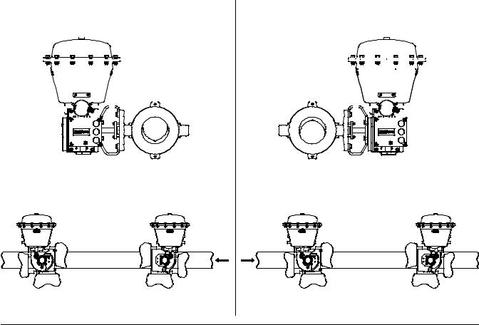
Figure 2. Fisher 2052 Actuator Mounting Styles |
|
|
|
|
|
|
|
|
|
|
|
|
|
|
|
|
|
|
|
|
|
|
|
|
|
|
|
|
|
|
|
|
|
|
|
|
|
|
|
|
|
|
|
|
||||||||||||||||||||||||||||||||
|
|
|
LEFT HAND MOUNTING |
|
|
|
|
|
|
|
|
RIGHT HAND MOUNTING |
||||||||||||||||||||||||||||||||||||||||||||||||||||||||||||||||
|
|
|
|
|
|
|
|
|
|
|
|
|
|
|
|
|
|
|
|
|
|
|
|
|
|
|
|
|
|
|
|
|
|
|
|
|
|
|
|
|
|
|
|
|
|
|
|
|
|
|
|
|
|
|
|
|
|
|
|
|
|
|
|
|
|
|
|
|
|
|
|
|
|
|
|
|
|
|
|
|
|
|
|
|
|
|
|
|
|
|
|
|
|
|
|
|
|
|
|
|
|
|
|
|
|
|
|
|
|
|
|
|
|
|
|
|
|
|
|
|
|
|
|
|
|
|
|
|
|
|
|
|
|
|
|
|
|
|
|
|
|
|
|
|
|
|
|
|
|
|
|
|
|
|
|
|
|
|
|
|
|
|
|
|
|
|
|
|
|
|
|
|
|
|
|
|
|
|
|
|
|
|
|
|
|
|
|
|
|
|
|
|
|
|
|
|
|
|
|
|
|
|
|
|
|
|
|
|
|
|
|
|
|
|
|
|
|
|
|
|
|
|
|
|
|
|
|
|
|
|
|
|
|
|
|
|
|
|
|
|
|
|
|
|
|
|
|
|
|
|
|
|
|
|
|
|
|
|
|
|
|
|
|
|
|
|
|
|
|
|
|
|
|
|
|
|
|
|
|
|
|
|
|
|
|
|
|
|
|
|
|
|
|
|
|
|
|
|
|
|
|
|
|
|
|
|
|
|
|
|
|
|
|
|
|
|
|
|
|
|
|
|
|
|
|
|
|
|
|
|
|
|
|
|
|
|
|
|
|
|
|
|
|
|
|
|
|
|
|
|
|
|
|
|
|
|
|
|
|
|
|
|
|
|
|
|
|
|
|
|
|
|
|
|
|
|
|
|
|
|
|
|
|
|
|
|
|
|
|
|
|
|
|
|
|
|
|
|
|
|
|
|
|
|
|
|
|
|
|
|
|
|
|
|
|
|
|
|
|
|
|
|
|
|
|
|
|
|
|
|
|
|
|
|
|
|
|
|
|
|
|
|
|
|
|
|
|
|
|
|
|
|
|
|
|
|
|
|
|
|
|
|
|
|
|
|
|
|
|
|
|
|
|
|
|
|
|
|
|
|
|
|
|
|
|
|
|
|
|
|
|
|
|
|
|
|
|
|
|
|
|
|
|
|
|
|
|
|
|
|
|
|
|
|
|
|
|
|
|
|
|
|
|
|
|
|
|
|
|
|
|
|
|
|
|
|
|
|
|
VALVE |
VALVE |
|
|
INLET |
INLET |
|
|
STYLE D SHOWN |
|
STYLE B SHOWN |
|
|
|
|
STYLE D |
STYLE C |
STYLE A |
STYLE B |
|
POSITION 1 |
|
POSITION 1 |
|
STANDARD |
|
STANDARD |
2 |
4 |
|
|
FLOW |
2 |
4 |
|
2 |
|
|
2 |
||||
4 |
|
|
|
4 |
|
||
3 |
|
3 |
FLOW |
|
3 |
|
3 |
|
|
|
|
GE37285-B
Specifications
Specifications are shown in table 1 for 2052 actuators. Specifications for actuator operation are stamped on a metal nameplate attached to the actuator.
3

2052 Actuator |
|
|
|
|
|
Instruction Manual |
|
November 2011 |
|
|
|
|
|
D103296X012 |
|
|
|
|
|
|
|
|
|
Table 6. Bolting Torque Requirements(1) |
|
|
|
|
|
||
DESCRIPTION KEY NUMBER |
ACTUATOR |
|
|
TORQUE |
FASTENER LUBRICATION |
|
|
SIZE |
|
NSm |
|
LbfSft |
|
||
|
|
|
|
|
|||
Rod End Bearing Clamping Bolt |
1 |
|
38 |
|
28 |
None |
|
2 |
|
180 |
|
130 |
|
||
Torque , Key 16 |
|
|
|
||||
3 |
|
400 |
|
295 |
|
|
|
|
|
|
|
|
|||
|
|
|
|
|
|
|
|
End Plate to Housing Bolt |
1 |
|
68 |
|
50 |
None |
|
2 |
|
120 |
|
90 |
|
||
Torque, Key 4 |
|
|
|
||||
3 |
|
210 |
|
155 |
|
|
|
|
|
|
|
|
|||
|
|
|
|
|
|
|
|
Diaphragm Plate to Rod Bolt |
1 |
|
27 |
|
20 |
Anti-Seize Lubricant |
|
2 |
|
115 |
|
85 |
|
||
Torque, Key 7 |
|
|
|
||||
3 |
|
300 |
|
220 |
|
|
|
|
|
|
|
|
|||
|
|
|
|
|
|
|
|
Casing Bolt Torque, Key 8 |
1 |
|
55 |
|
40 |
None |
|
2 |
|
55 |
|
40 |
|
||
|
3 |
|
55 |
|
40 |
|
|
|
|
|
|
|
|
|
|
Housing to Yoke Bolt Torque, |
1 |
|
27 |
|
20 |
None |
|
2 |
|
68 |
|
50 |
|
||
Key 28 |
|
|
|
||||
3 |
|
245 |
|
180 |
|
|
|
|
|
|
|
|
|||
|
|
|
|
|
|
|
|
Lever-Spline Clamping Bolt |
1 |
|
38 |
|
28 |
None |
|
2 |
|
115 |
|
85 |
|
||
Torque, Key 15 |
|
|
|
||||
3 |
|
175 |
|
130 |
|
|
|
|
|
|
|
|
|||
|
|
|
|
|
|
|
|
Optional Lockout Kit Mounting |
1 |
|
NA |
|
NA |
None |
|
2 |
|
88 |
|
65 |
|
||
Bolt Torque, Key 53 |
|
|
|
||||
3 |
|
340 |
|
250 |
|
|
|
|
|
|
|
|
|||
|
|
|
|
|
|
|
|
1. Exceeding any torque requirements could damage the actuator and impair safe operation.
Installation

 WARNING
Always wear protective gloves, clothing, and eyewear when performing any installation operations.
Check with your process or safety engineer for any other hazards that may be present from exposure to process media.
If installing into an existing application, also refer to the WARNING at the beginning of the Maintenance section in this instruction manual.
CAUTION
To avoid parts damage, do not apply pressure that exceeds the Maximum Diaphragm Casing Pressure in table 1.
Use pressure-limiting or pressure-relieving devices to prevent the Operating Pressure from exceeding the values shown in table 3.
The actuator, as it comes from the factory, is normally mounted on a valve body. If the actuator is shipped separately or if it is necessary to mount the actuator on the valve, perform the procedures presented in the Actuator Mounting section. Follow the procedures given in the valve instruction manual when installing the control valve in the pipeline.
If a positioner is ordered with the actuator, the pressure connection to the actuator is normally made at the factory. If it is necessary to make this connection, run tubing of the appropriate size for the diaphragm casing pressure connection (reference table 4) between the pressure connection and the instrument. Keep the length of tubing or pipe as short as possible to avoid transmission lag in the control signal.
When the control valve is completely installed and connected to the controlling instrument, check to make sure that the action is correct (air-to-open or air-to-close) and that the controlling instrument is properly configured for the
4

Instruction Manual |
2052 Actuator |
D103296X012 |
November 2011 |
|
|
desired action. For successful operation, the diaphragm rod assembly, lever, and valve shaft must move freely in response to changes in the loading pressure on the diaphragm.
Actuator Mounting

 WARNING
Avoid personal injury or property damage from sudden release of process pressure or bursting of parts. Before performing any maintenance operations:
D Do not remove the actuator from the valve while the valve is still pressurized.
D Always wear protective gloves, clothing, and eyewear when performing any maintenance operations.
DDisconnect any operating lines providing air pressure, electric power, or a control signal to the actuator. Be sure the actuator cannot suddenly open or close the valve.
DUse bypass valves or completely shut off the process to isolate the valve from process pressure. Relieve process pressure from both sides of the valve. Drain the process media from both sides of the valve.
D Safely vent the power actuator loading pressure.
D Use lock-out procedures to be sure that the above measures stay in effect while you work on the equipment.
DThe valve packing box may contain process fluids that are pressurized, even when the valve has been removed from the pipeline. Process fluids may spray out under pressure when removing the packing hardware or packing rings.
D Check with your process or safety engineer for any hazards that may be present from exposure to process media.
Use the following steps to mount the actuator or to change actuator mounting style or position.
Unless otherwise specified, key numbers referenced in the following procedures are shown in figure 7 for the 2052 actuator.
If the Actuator is mounted on a valve body and it is necessary to change mounting style or position, the actuator must first be separated from the valve body.
1.Isolate the valve body from the process. Release process pressure and vent all actuator pressure.
2.Remove the cover or plug (key 2).

 WARNING
To avoid personal injury and equipment damage from moving parts, keep fingers and tools clear while stroking the actuator with the cover removed.
3.Loosen the cap screw (key 15).
4.Separate the actuator from the valve body by removing the cap screws and nuts which secure the valve to the mounting yoke (key 27). Proceed to step 5.
If the actuator is not mounted on a valve body ensure the up and down travel stops (see figure 3) are adjusted correctly to achieve the desired actuator rotation. Use the travel indicator (key 21) and travel scale (key 19) as reference.
Note
Once each travel stop is properly positioned, adequately tighten the hex nut (key 24) to lock the travel stop in place.
5

2052 Actuator |
Instruction Manual |
November 2011 |
D103296X012 |
|
|
5.Refer to figure 2 and table 5 for available mounting styles and positions. The actuator is normally positioned vertically with the valve in a horizontal pipeline.
6.Determine whether the actuator mounting yoke (key 27) will be mounted on the end plate assembly (key 3) side or on the actuator housing boss side of the actuator. If the desired mounting position and style require moving the mounting yoke (key 27) and travel indicator components to opposite sides of the actuator, remove the machine screws (keys 20 and 22), the travel indicator scale (key 19), and the travel indicator (key 21). Remove the cap screws (key 28) and the mounting yoke (key 27). Install the mounting yoke in the desired position (on the end plate assembly or on the actuator housing boss). Tighten the mounting cap screws to the torque specified in table 6. Install the travel indicator components on the opposite side of the actuator.

 WARNING
To avoid personal injury or property damage, ensure the travel indicator is installed correctly to coincide with the desired actuator action. Refer to figure 3 for more information.
Figure 3. Fisher 2052 Actuator Travel Stops and Travel Indication
INDICATOR
ORIENTATION
FOR PDTO
TRAVEL INDICATOR
SCALE INDICATOR
ORIENTATION
FOR PDTC
VIEW A
|
|
KEY 22 |
|
DOWN |
|
|
|
TRAVEL |
UP |
KEY 20 |
TRAVEL |
STOP |
TRAVEL |
|
INDICATOR |
|
STOP |
|
|
|
|
|
VIEW A |
7. Before sliding the valve shaft into the lever, position the valve ball or disk as follows: For push-down-to-close action, the valve ball or disk should be in the fully open position.
For push-down-to-open action, the valve ball or disk should be in the fully closed position (see the valve body instruction manual).
8.Make sure that the index markings on the valve shaft are properly aligned with either the markings on the lever or the travel indicator scale mounting holes. Slide the valve shaft into the lever. (See figure 4 for one possible orientation.) Install the valve mounting cap screws and nuts. Tighten to the torque value given in the appropriate valve body instruction manual.
6
 Loading...