


Instruction Manual |
3660 and 3661 Positioners |
D101402X012 |
January 2013 |
|
|
Fisherr 3660 and 3661 Positioners
Contents |
|
Introduction . . . . . . . . . . . . . . . . . . . . . . . . . . . . . . . . . |
2 |
Scope of Manual . . . . . . . . . . . . . . . . . . . . . . . . . . . . . |
2 |
Description . . . . . . . . . . . . . . . . . . . . . . . . . . . . . . . . . |
2 |
Specifications . . . . . . . . . . . . . . . . . . . . . . . . . . . . . . . |
2 |
Educational Services . . . . . . . . . . . . . . . . . . . . . . . . . |
2 |
Installation . . . . . . . . . . . . . . . . . . . . . . . . . . . . . . . . . . |
5 |
Hazardous Area Classifications and Special |
|
Instructions for “Safe Use” and Installation |
|
in Hazardous Locations for 3661 Positioner . . . . |
5 |
CSA . . . . . . . . . . . . . . . . . . . . . . . . . . . . . . . . . . . . |
5 |
FM . . . . . . . . . . . . . . . . . . . . . . . . . . . . . . . . . . . . . |
6 |
ATEX . . . . . . . . . . . . . . . . . . . . . . . . . . . . . . . . . . . |
6 |
IECEx . . . . . . . . . . . . . . . . . . . . . . . . . . . . . . . . . . . |
7 |
Positioner Mounting . . . . . . . . . . . . . . . . . . . . . . . . . |
8 |
Mounting on 1250, 1250R, 3024S |
|
and GX Actuators . . . . . . . . . . . . . . . . . . . . . . |
8 |
Mounting on Baumannt Actuators . . . . . . . . |
12 |
Mounting on 657 and 667 Actuators . . . . . . . |
13 |
Feedback Lever Assembly and |
|
Range Spring Installation . . . . . . . . . . . . . . . . . . |
16 |
Pressure Connections . . . . . . . . . . . . . . . . . . . . . . . |
19 |
Supply Connection . . . . . . . . . . . . . . . . . . . . . . |
19 |
Output Connection . . . . . . . . . . . . . . . . . . . . . . |
21 |
Instrument Connection . . . . . . . . . . . . . . . . . . |
21 |
Diagnostic Connections . . . . . . . . . . . . . . . . . . |
21 |
Vent Connection . . . . . . . . . . . . . . . . . . . . . . . . . . . |
22 |
Electrical Connections for 3661 Positioners . . . . . |
22 |
Calibration . . . . . . . . . . . . . . . . . . . . . . . . . . . . . . . . . . |
23 |
Split Range Operation . . . . . . . . . . . . . . . . . . . . . . . |
25 |
3660 Bypass Operation . . . . . . . . . . . . . . . . . . . . . . . |
26 |
Principle of Operation . . . . . . . . . . . . . . . . . . . . . . . . |
27 |
Maintenance . . . . . . . . . . . . . . . . . . . . . . . . . . . . . . . . |
28 |
Changing the Positioner Action . . . . . . . . . . . . . . . |
29 |
Changing the Range Spring . . . . . . . . . . . . . . . . . . |
29 |
Changing the Input Signal Range on |
|
3660 Positioners . . . . . . . . . . . . . . . . . . . . . . . . . |
29 |
Removing the Positioner from the Actuator . . . . . |
29 |
Center Bolt Mounting on 1250, 1250R, |
|
3024S and Baumann Actuators . . . . . . . . . |
29 |
Clamp Mounting on 1250, 1250R |
|
and 3024S Actuators . . . . . . . . . . . . . . . . . . |
30 |
Mounting Bracket/U Bolt Mounting on |
|
657 and 667 Actuators . . . . . . . . . . . . . . . . |
30 |
Figure 1. Fisher 3660 Positioner Mounted on a Baumann Actuator
W7174 |
|
Changing the Input Module |
|
Diaphragm Assembly . . . . . . . . . . . . . . . . . . . . . |
30 |
Disassembling and Assembling Relay |
|
Components . . . . . . . . . . . . . . . . . . . . . . . . . . . . |
31 |
Disassembling and Assembling the Bypass |
|
Valve . . . . . . . . . . . . . . . . . . . . . . . . . . . . . . . . . . . |
32 |
Replacing the 3661 Converter Module . . . . . . . . . |
33 |
Parts Ordering . . . . . . . . . . . . . . . . . . . . . . . . . . . . . . . |
33 |
Parts Kits . . . . . . . . . . . . . . . . . . . . . . . . . . . . . . . . . . . |
34 |
Repair Kits . . . . . . . . . . . . . . . . . . . . . . . . . . . . . . . . . |
34 |
Mounting Kits . . . . . . . . . . . . . . . . . . . . . . . . . . . . . . |
34 |
Parts List . . . . . . . . . . . . . . . . . . . . . . . . . . . . . . . . . . . |
34 |
Positioner Common Parts . . . . . . . . . . . . . . . . . . . . |
34 |
Diagnostic Connections . . . . . . . . . . . . . . . . . . . . . |
39 |
Mounting Parts . . . . . . . . . . . . . . . . . . . . . . . . . . . . . |
39 |
Loop Schematics/Nameplates for |
|
3661 Positioner . . . . . . . . . . . . . . . . . . . . . . . . . . . . . |
42 |
www.Fisher.com
3660 and 3661 Positioners |
Instruction Manual |
January 2013 |
D101402X012 |
|
|
Introduction
Scope of Manual
This instruction manual includes installation, operation, calibration, maintenance, and parts ordering information for Fisher 3660 and 3661 positioners. Refer to separate instruction manuals for information on the actuator and control valve.
Do not install, operate, or maintain a 3660 or 3661 positioner without being fully trained and qualified in valve, actuator and accessory installation, operation and maintenance. To avoid personal injury or property damage it is important to carefully read, understand, and follow all of the contents of this manual, including all safety cautions and warnings. If you have any questions about these instructions, contact your Emerson Process Management sales office before proceeding.
Description
3660 pneumatic and 3661 electro pneumatic, single acting positioners are used with Fisher 657, 667, 1250, 1250R, 3024S, and GX actuators. These positioners can also be mounted on Baumann actuators. Figure 1 shows a 3660 positioner mounted on a Baumann actuator.
The positioner mounts on the actuator and provides the desired plug position for a specific input signal. The 3660 positioner accepts a pneumatic signal and the 3661 accepts a 4 to 20 milliampere DC input signal.
Specifications
Specifications for the 3660 and 3661 positioners are shown in table 1.
Educational Services
For information on available courses for 3660 and 3661 positioners, as well as a variety of other products, contact:
Emerson Process Management Educational Services, Registration P.O. Box 190; 301 S. 1st Ave. Marshalltown, IA 50158-2823 Phone: 800-338-8158 or
Phone: 641-754-3771
FAX: 641-754-3431
e mail: education@emerson.com
2

Instruction Manual |
3660 and 3661 Positioners |
D101402X012 |
January 2013 |
|
|
Table 1. Specifications
Available Configuration
3660: Single acting pneumatic valve positioner 3661: Single acting electro pneumatic valve positioner
Input Signal
3660
J0.2 to 1.0 bar (3 to 15 psig),
J0.4 to 2.0 bar (6 to 30 psig), or
Jsplit range (see tables 7 and 8)
3661:
JÉ4 to 20 mA DC constant current with 30 VDC maximum compliance voltage.
Jsplit range is also available, see tables 7 and 8
Equivalent Circuit (3661)
120 ohms shunted by three 5.6 V zener diodes
Output Signal
Type: Pneumatic pressure as required by the actuator up to full supply pressure
Action:
JDirect (increasing input signal pressure increases positioner output),
JReverse (increasing input signal pressure decreases positioner output)
Supply Pressure(1)
Recommended: 10% above actuator requirements Maximum: 6.2 bar (90 psig) or pressure rating of actuator, whichever is lower
Medium: air
3660 and 3661 are not compatible with natural gas as the supply medium
Performance
Independent Linearity: ±1% of output span
Hysteresis: 0.5% of output span(2) Deadband: 0.1% of input span
Electromagnetic Compatibility for 3661 electro pneumatic positioner:
Meets EN 61326 1 (First Edition) ÃImmunity—Industrial locations per Table 2 of ÃÃthe EN 61326 1 standard. Performance is ÃÃshown in table 2 below.
Emissions—Class A
ÃISM equipment rating: Group 1, Class A
Positioner Adjustments
Span: J Adjustable up to 20 mm (0.75 inch) stem travel, or J Adjustable from 20 mm (0.75 inch) to 50 mm (2 inch) stem travel
Zero: 0 to 100%
Gain: 0.5 to 6% PB (proportional band)(3)
Output Volume Damping: Loop dynamic response adjustment
Delivery Capacity(4)
1.4 Bar (20 Psig) Supply: 4.3 normal m3/hour (150 scfh)
2.4 Bar (35 Psig) Supply: 6.6 normal m3/hour (230 scfh)
Exhaust Capacity(4)
1.4 Bar (20 Psig) Supply: 4.8 normal m3/hour (170 scfh)
2.4 Bar (35 Psig) Supply: 7.4 normal m3/hour (260 scfh)
Steady State Air Consumption(4,5)
3660: 0.17 normal m3/hour (6.0 scfh) at 1.4 bar (20 psig) supply pressure. 0.22 normal m3/hour (7.9 scfh) at 2.4 bar (35 psig) supply pressure 3661: 0.24 normal m3/hour (8.8 scfh) at 1.4 bar (20 psig) supply pressure. 0.33 normal m3/hour (12.3 scfh) at 2.4 bar (35 psig) supply pressure
Operating Influence
Supply Pressure: 70 mbar (1 psig) change in supply pressure changes the actuator stem position less than 0.16%(6) of travel
Operative Temperature Limits(1)
3660 without Pressure Gauges: -40 to 121°C (-40 to 250°F)
3660 with Pressure Gauges: -40 to 82°C (-40 to 180°F)
3661 with or without Pressure Gauges: -40 to 82°C (-40 to 180°F)
Hazardous Area Classification for 3660
3660 pneumatic positioners comply with the requirements of ATEX Group II Category 2 Gas and Dust
- continued -
3

3660 and 3661 Positioners |
Instruction Manual |
January 2013 |
D101402X012 |
|
|
Table 1. Specifications (Continued)
Hazardous Area Classification for 3661
CSA—Intrinsically Safe, Type n, Non incendive FM—Intrinsically Safe, Type n, Non incendive
ATEX—Intrinsically Safe, Type n (Gas Atmospheres Only)
IECEx—Intrinsically Safe, Type n (Gas Atmospheres Only)
Refer to Hazardous Area Classifications and Special Instructions for “Safe Use” and Installation in Hazardous Locations, starting on page 5, for additional information.
Housing Classification for 3661
CSA—Type 3 Encl.
FM—NEMA 3, IP54 ATEX—IP44
IECEx—IP44
Mounting orientation requires vent location to be below horizontal.
Other Classifications/Certifications for 3661
KGS—Korea Gas Safety Corporation
Mounting
The positioner can be mounted in one of four different configurations. See figure 2 for mounting.
Pressure Connections
1/4 NPT internal
Conduit Connection for 3661
1/2 NPT (M20 or PG13 adaptors, optional)
Maximum Valve Stem Travel
Two ranges:
J50 mm (2 inch) to 20 mm (0.75 inch) minimum;
J20 mm (0.75 inch) adjustable to lesser travel with standard input signal
Approximate Weight
3660: 1.2 kg (2.6 pounds) 3661: 1.4 kg (3.0 pounds)
Vent Connection
1/4 NPT internal
Options
3660: J Instrument and output pressure gauges, J Integrally mounted bypass valve
3661: Output pressure gauge
Declaration of SEP
Fisher Controls International LLC declares this product to be in compliance with Article 3 paragraph 3 of the Pressure Equipment Directive (PED) 97 / 23 / EC. It was designed and manufactured in accordance with Sound Engineering Practice (SEP) and cannot bear the CE marking related to PED compliance.
However, the product may bear the CE marking to indicate compliance with other applicable European Community Directives.
NOTE: Specialized instrument terms are defined in ANSI/ISA Standard 51.1 - Process Instrument Terminology.
1. The pressure/temperature limits in this manual and any applicable standard or code limitation should not be exceeded. 2. Hysteresis value at a gain setting of 1/2 turn.
3. Adjusting the gain (PB) adjustment changes the nozzle flapper relationship. This nozzle flapper change affects the actuator/positioner response time. 4. Normal m3/hr—normal cubic meters per hour (0°C and 1.01325 bar absolute); Scfh—standard cubic feet per hour (60°F and 14.7 psia).
5. Air consumption at a gain setting of 1/2 turn. 6. At supply pressure of 2.4 bar (35 psig).
Table 2. Fisher 3661 Positioner EMC Summary Results—Immunity
Port |
Phenomenon |
Basic Standard |
Test Level |
Performance |
|
|
Criteria(1) |
|
|||||
|
|
|
|
|
||
|
Electrostatic discharge (ESD) |
IEC 61000 4 2 |
4 kV contact |
A |
||
|
8 kV air |
|||||
|
|
|
|
|
||
|
|
|
|
|
|
|
Enclosure |
|
|
80 to 1000 MHz @ 10V/m with 1 kHz AM at 80% |
|
|
|
Radiated EM field |
IEC 61000 4 3 |
1400 to 2000 MHz @ 3V/m with 1 kHz AM at 80% |
A |
|||
|
||||||
|
|
|
2000 to 2700 MHz @ 1V/m with 1 kHz AM at 80% |
|
|
|
|
|
|
|
|
||
|
Rated power frequency magnetic field |
IEC 61000 4 8 |
60 A/m at 50 Hz |
A |
||
|
|
|
|
|
||
|
Burst |
IEC 61000 4 4 |
1 kV |
A |
||
I/O |
|
|
|
|
|
|
Surge |
IEC 61000 4 5 |
1 kV (line to ground only, each) |
B |
|||
signal/control |
||||||
|
|
|
|
|
||
Conducted RF |
IEC 61000 4 6 |
150 kHz to 80 MHz at 3 Vrms |
A |
|||
|
||||||
|
|
|
|
|
|
|
Specification limit = ±1% of span
1. A = No degradation during testing. B = Temporary degradation during testing, but is self recovering.
4

Instruction Manual |
3660 and 3661 Positioners |
D101402X012 |
January 2013 |
|
|
Installation
Typically, a positioner is shipped with the actuator. If so, the factory mounts and calibrates the positioner and connects the positioner to actuator tubing. If the positioner is ordered separately from the actuator, perform the appropriate mounting procedure. Refer to the appropriate instruction manuals for actuator and valve installation procedures.

 WARNING
Always wear protective clothing, gloves, and eyewear when performing any Installation procedures to avoid personal injury.
If installing into an existing application, also refer to the WARNING at the beginning of the Maintenance section in this instruction manual.
Check with your process or safety engineer for any additional measures that must be taken to protect against process media.
Hazardous Area Classifications and Special Instructions for “Safe Use” and Installation in Hazardous Locations for 3661 Positioner
Certain nameplates may carry more than one approval, and each approval may have unique installation/wiring requirements and/or conditions of “safe use”. These special instructions for “safe use” are in addition to, and may override, the standard installation procedures. Special instructions are listed by approval.
Note
This information supplements the nameplate markings affixed to the product.
Always refer to the nameplate itself to identify the appropriate certification.

 WARNING
Failure to follow these conditions of “safe use” could result in personal injury or property damage from fire or explosion, and area re classification.
CSA
Special Conditions of Safe Use
Intrinsically Safe and Non incendive
No special conditions for safe use.
Type n
Type n installations must be in a suitable (IP5X) enclosure.
Refer to table 3 for additional approval information, figure 27 for CSA loop schematics, and figure 28 for a typical CSA/FM approval nameplate.
5
3660 and 3661 Positioners |
Instruction Manual |
January 2013 |
D101402X012 |
|
|
Table 3. Hazardous Area Classifications for Fisher 3661 Positioner—CSA (Canada)
Certification |
Certification Obtained |
Entity Rating |
Temperature Code |
Enclosure Rating |
|
Body |
|||||
|
|
|
|
||
|
Intrinsically Safe |
Vmax = 30 VDC |
T4 (Tamb ≤ 82°C) |
|
|
|
Imax = 150 mA |
|
|||
|
Ex ia IIC T4/T5/T6 per drawing GE28591 |
|
|||
|
Pi = 1.25 W |
T5 (Tamb ≤ 62°C) |
CSA Type 3 Encl. |
||
|
Class I, II Division 1 GP A,B,C,D,E,F,G |
||||
|
Ci = 0 nF |
T6 (Tamb ≤ 47°C) |
|
||
|
T4/T5/T6 per drawing GE28591 |
|
|||
CSA |
Li = 0 mH |
|
|
||
|
|
|
|||
|
|
|
|
|
|
|
Type n |
- - - |
T6 (Tamb ≤ 82°C) |
CSA Type 3 Encl. |
|
|
Ex nA IIC T6 |
||||
|
|
|
|
||
|
|
|
|
|
|
|
Class I Division 2 GP A,B,C,D T6 |
- - - |
T6 (Tamb ≤ 82°C) |
CSA Type 3 Encl. |
|
|
|
|
|
|
FM
Intrinsically Safe, Type n, and Non incendive
No special conditions for safe use.
Refer to table 4 for approval information, figure 29 for the FM loop schematic, and figure 28 for a typical CSA/FM approval nameplate.
Table 4. Hazardous Area Classifications for Fisher 3661 Positioner—FM (United States)
Certification |
Certification Obtained |
Entity Rating |
Temperature Code |
Enclosure Rating |
|
Body |
|||||
|
|
|
|
||
|
Intrinsically Safe |
Vmax = 30 VDC |
T4 (Tamb ≤ 82°C) |
|
|
|
Class I Zone 0 AEx ia IIC T4/T5/T6 per drawing |
Imax = 150 mA |
|
||
|
GE28590 |
Pi = 1.25 W |
T5 (Tamb ≤ 62°C) |
NEMA 3, IP54 |
|
|
Class I, II, III Division 1 GP A,B,C,D,E,F,G |
Ci = 0 nF |
T6 (Tamb ≤ 47°C) |
|
|
FM |
T4/T5/T6 per drawing GE28590 |
Li = 0 mH |
|
|
|
|
|
|
|
||
|
Type n |
- - - |
T5 (Tamb ≤ 82°C) |
NEMA 3, IP54 |
|
|
Class I Zone 2 AEx nA IIC T5 |
||||
|
|
|
|
||
|
|
|
|
|
|
|
Class I Division 2, GP A,B,C,D T5 |
- - - |
T5 (Tamb ≤ 82°C) |
NEMA 3, IP54 |
|
|
Class II, III Division 2, GP F,G T5 |
||||
|
|
|
|
||
|
|
|
|
|
ATEX
Special Conditions for Safe Use
Intrinsically Safe
This equipment is intrinsically safe and can be used in potentially explosive atmospheres.
The electrical parameters of certified equipment which can be connected to the device must not exceed the following value: U0 ≤ 30 Vdc; I0 ≤ 150 mA; P0 ≤ 1.25 W.
Ambient Temperature:
T6, at Tamb = 47_C
T5, at Tamb = 62_C
T4, at Tamb = 71_C
6

Instruction Manual |
3660 and 3661 Positioners |
D101402X012 |
January 2013 |
|
|
Type n
The 3661 has an IP44 ingress protection: it is only intended to be installed in an area where a convenient protection is ensured against the entry of solid foreign bodies and liquids which may decrease the safety.
Refer to table 5 for additional approval information and figure 30 for a typical ATEX/IECEx approval nameplate.
Table 5. Hazardous Area Classifications for Fisher 3661 Positioner—ATEX
Certificate |
Certification Obtained |
Entity Rating |
Temperature Code |
Enclosure Rating |
|
II 1 G |
Ui = 30 VDC |
T4 (Tamb ≤ 82°C) |
|
|
Ii = 150 mA |
|
||
|
Intrinsically Safe |
|
||
|
Pi = 1.25 W |
T5 (Tamb ≤ 62°C) |
IP44 |
|
|
Gas |
|||
|
Ci = 0 nF |
T6 (Tamb ≤ 47°C) |
|
|
|
Ex ia IIC T4/T5/T6 |
|
||
ATEX |
Li = 0 mH |
|
|
|
|
|
|
||
|
II 3 G |
|
|
|
|
Type n |
- - - |
T6 (Tamb ≤ 82°C) |
IP44 |
|
Gas |
|||
|
|
|
|
|
|
Ex nA IIC T6 |
|
|
|
|
|
|
|
|
IECEx
Conditions of Certification
Intrinsically Safe

 WARNING
Substitution of components may impair intrinsic safety.
-40_C Ta +82_C; T6 (Ta +47_C); T5 (Ta +62_C)
Entity Parameters
Ui = 30 V, li = 150 mA, Pi = 1.25 W, Ci = 0 nF, Li = 0 mH
Type n

 WARNING
Disconnect power before opening.
-40_C Ta +82_C; T6 (Ta +82_C)
Refer to table 6 for additional approval information, and figure 30 for a typical ATEX/IECEx approval nameplate.
Table 6. Hazardous Area Classifications for Fisher 3661 Positioner—IECEx
Certificate |
Certification Obtained |
Entity Rating |
Temperature Code |
Enclosure Rating |
|
|
Ui = 30 VDC |
T4 (Tamb ≤ 82°C) |
|
|
Intrinsically Safe |
Ii = 150 mA |
|
|
|
Gas |
Pi = 1.25 W |
T5 (Tamb ≤ 62°C) |
IP44 |
IECEx |
Ex ia IIC T4/T5/T6 |
Ci = 0 nF |
T6 (Tamb ≤ 47°C) |
|
|
Li = 0 mH |
|
|
|
|
|
|
|
|
|
|
|
|
|
|
Type n |
|
T6 (Tamb ≤ 82°C) |
|
|
Gas |
- - - |
IP44 |
|
|
Ex nA IIC T6 |
|
|
|
|
|
|
|
|
7
3660 and 3661 Positioners |
Instruction Manual |
January 2013 |
D101402X012 |
|
|
Positioner Mounting
Mounting on 1250, 1250R, 3024S, and GX Actuators
During the following mounting procedures, refer to figures 3, 24, and 25 for key number locations.
Figure 3 shows keys 64 through 78 and 101 through 104. Other key numbers are shown in either figure 24 for the 3660 positioner or figure 25 for the 3661 positioner. Two mounting methods are available, center bolt mounting and clamp mounting.
1.Determine the positioner mounting configuration from figure 2. The actuator size, actuator travel, and positioner action must be known. If center bolt mounting is desired, be certain the actuator is equipped with tapped holes in the posts.
2.Thread the hex head screws with washers (keys 69 and 70) several turns into the stem connector. The feedback plate (key 68) is reversible and must be positioned so that the pilot shaft (key 19A) will operate correctly in the slot of the feedback plate. For actuator travels between 20 and 30 mm (0.787 and 1.18 inches) (for 3024S actuators, travel ranges between 16 and 32 mm), position the feedback plate so the long portion of its slot, when bolted to the stem connector, is closest to the positioner as shown in figure 4. For travels greater than 30 mm (1.18 inches), reverse the position of the feedback plate as shown in figure 4.
a.For size 30 and 34 actuators with all travels and for size 45 actuators with travel greater than 30 mm (1.18 inches), position the feedback plate (key 68) between the stem connector and washers and tighten the hex head screws (key 69).
b.For size 45 actuators with travel between 20 and 30 mm (0.787 and 1.18 inches) (16 and 32 mm for 3024S actuators), attach the feedback adaptor (key 103) to the feedback plate (key 68) using machine screws, lockwashers, and wedge nuts (keys 102, 101, and 104). The feedback plate and the wedge nuts must be assembled as shown in the lower right portion of figure 3. Use the mounting holes in the feedback adaptor and position it as indicated in figure 4. Then, position the feedback plate between the stem connector and washers and tighten the hex head screws (key 69).
3.Unscrew the two machine screws (key 24), and remove the positioner cover (key 21).
Center Bolt Mounting (GX Actuator)
a.As shown in figure 5, a thin knockout section is cast across the mounting hole in the housing. Check to make certain this knockout section has been removed. If the knockout section has not been removed, use a punch to knock it out.
b.Attach the positioner to the actuator using a sealing washer and hex head screw (keys 71 and 72).
c.Install the feedback lever assembly and range spring.
Clamp Mounting
a.Install a hex nut (key 66) on one end of each of two studs (key 65). Turn the nuts all the way to the end of the threads.
b.Thread the end of each stud (key 65), (the end with hex nut—key 66), into the back of the positioner housing (key 1) as far as the studs will go. Tighten both nuts against the housing.
c.Set the actuator at mid travel using a manual loading regulator.
d.With the finger end of the bracket (key 64) toward the positioner pressure connections as shown in figure 3, place the bracket and washers (key 67) over the studs (key 65). Thread the hex nuts (key 66) several turns onto the studs.
8
Instruction Manual |
3660 and 3661 Positioners |
D101402X012 |
January 2013 |
|
|
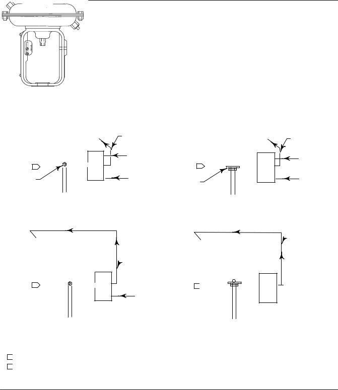
Figure 2. Mounting Configurations
Input Signal |
Positioner Output |
Direct |
|
0.2 to 1.0 bar (3 to 15 psig) |
|
0.4 to 2.0 bar (6 to 30 psig) |
|
4 to 20 mA |
|
|
|
Reverse |
Up to 6.2 bar (90 psig) |
1.0 to 0.2 bar (15 to 3 psig) |
|
2.0 to 0.4 bar (30 to 6 psig) |
|
20 to 4 mA |
|
|
|
For split range signal refer to tables 7 and 8 |
|
|
|
|
OUTPUT |
|
OUTPUT |
|
|
|
|
|
AIR SUPPLY |
|
INPUT SIGNAL |
|
|
|
|
1 |
|
|
2 |
PILOT SHAFT |
INPUT SIGNAL |
FEEDBACK |
AIR SUPPLY |
|
|
|
|
|
|
PLATE |
|
ACTUATOR: AIR TO RETRACT
POSITIONER ACTION: DIRECT (INCREASING INPUT SIGNAL INCREASES OUTPUT PRESSURE TO ACTUATOR)
 OUTPUT
 AIR SUPPLY
1
INPUT SIGNAL
ACTUATOR: AIR TO EXTEND
POSITIONER ACTION: REVERSE (INCREASING INPUT SIGNAL DECREASES OUTPUT PRESSURE TO ACTUATOR)
ACTUATOR: AIR TO RETRACT
POSITIONER ACTION: REVERSE (INCREASING INPUT SIGNAL DECREASES OUTPUT PRESSURE TO ACTUATOR)
 OUTPUT
 INPUT SIGNAL
2
 AIR SUPPLY
ACTUATOR: AIR TO EXTEND
POSITIONER ACTION: DIRECT (INCREASING INPUT SIGNAL INCREASES OUTPUT PRESSURE TO ACTUATOR)
NOTES:
1  WHEN MOUNTING ON BAUMANN ACTUATORS, INSTALL FEEDBACK PLATE SO LIP IS UP. INSTALL FEEDBACK LEVER ARM ASSEMBLY, PRELOADED, SO PILOT SHAFT IS ON TOP OF THE FEEDBACK PLATE.
2  WHEN MOUNTING ON BAUMANN ACTUATORS, INSTALL FEEDBACK PLATE SO LIP IS DOWN. INSTALL FEEDBACK LEVER ARM ASSEMBLY, PRELOADED, SO PILOT SHAFT IS UNDERNEATH THE FEEDBACK PLATE.
17B9106 B
17B9105 B
38B0195 B
A4035 2
9

3660 and 3661 Positioners |
Instruction Manual |
January 2013 |
D101402X012 |
|
|
Figure 3. Positioner Mounting on Fisher 1250, 1250R, and 3024S Actuators
MOUNT
NIPPLE MOUNTED
FILTER REGULATOR
CLAMP MOUNT
SECTION A A
WEDGE NUT |
FEEDBACK |
|
PLATE |
||
(KEY 104) |
||
(KEY 68) |
||
|
||
LOCKWASHER |
FEEDBACK |
|
ADAPTOR |
||
(K3Y 101) |
(KEY 103) |
|
|
MACHINE |
FEEDBACK |
|
|
LEVER |
|
|
|
SCREW |
|
|
|
ASSEMBLY |
|
|
|
(KEY 102) |
|
|
|
|
|
|
|
FILTER |
|
A |
A |
REGULATOR |
|
|
|
|
SIZE 45 WITH TRAVEL BETWEEN
20 AND 30 mm (0.787 AND 1.18 INCHES)
41B3946 F
10
Instruction Manual |
3660 and 3661 Positioners |
D101402X012 |
January 2013 |
|
|
Figure 4. Feedback Plate Orientation with Positioner Mounted on Fisher 1250, 1250R, and 3024S Actuators
FOR SIZE 30 AND 34 ACTUATORS WITH TRAVEL BETWEEN 20 AND 30 mm (0.787 AND 1.18 INCHES)
FOR SIZE 30,34 AND 45 ACTUATORS WITH TRAVEL GREATER THAN 30mm (1.18 INCHES)
B2260 1
Note
Do not install the range spring in the following step. Feedback lever assembly (key 19) installation in the next step is only temporary to permit verifying alignment.
e.Install the positioner on the actuator by placing the bracket (key 64) around the appropriate actuator leg. Visually center the center line of the slot in the feedback plate (key 68) with the center line of the hole in the housing. Then, tighten the nuts (key 66) only tight enough to prevent the positioner from moving on the actuator leg. Locate the feedback lever assembly (key 19) so that it may be temporarily installed into the positioner housing (key 1) and the feedback plate (key 68) to verify alignment. Do not install the range spring at this time. Place the pilot shaft (key 19A) in the slot of the feedback plate, and, at the same time, insert the feedback shaft in the hole of the positioner housing. Depress the feedback lever assembly inward until it stops against the housing. Make certain the slots in both the feedback lever assembly and the feedback plate are horizontal with each other and that the feedback lever assembly and the feedback plate are parallel with each
11

3660 and 3661 Positioners |
Instruction Manual |
January 2013 |
D101402X012 |
|
|
other. If necessary, correct alignment by loosening the hex nuts (key 66) and moving the positioner on the actuator leg as required.
f. Tighten the two hex nuts (key 66) to secure the positioner to the actuator leg.
g. Install the feedback lever assembly and range spring.
Mounting on Baumann Actuators
During the following mounting procedures, refer to figures 2, 5, 6, 24, and 25. Key numbers are shown in either figure 24 for the 3660 positioner or figure 25 for the 3661 positioner.
Figure 5. Actuator Center Bolt Mounting
THIN SECTION
A4949 1
Figure 6. Feedback Plate Installation for Baumann Actuators
ACTUATOR |
PILOT SHAFT |
STEM |
|
|
FEEDBACK LEVER |
|
ARM ASSEMBLY |
 1
1
VALVE
STEM FEEDBACK
PLATE
1 IF AFTER MOUNTING POSITIONER, THE FEEDBACK LEVER ARM ASSEMBLY WILL BE ON THE LEFT SIDE OF THE POSITIONER, INSTALL THE FEEDBACK PLATE SO THE LIP IS UP. INSTALL THE FEEDBACK LEVER ARM ASSEMBLY, PRELOADED, SO THE PILOT SHAFT IS ABOVE THE PLATE. IF AFTER MOUNTING POSITIONER, THE FEEDBACK LEVER ARM ASSEMBLY WILL BE ON THE RIGHT SIDE OF THE POSITIONER, INSTALL THE FEEDBACK PLATE SO THE LIP IS DOWN. INSTALL THE FEEDBACK LEVER ARM ASSEMBLY, PRELOADED, SO THE PILOT SHAFT IS BELOW THE PLATE.
A7223
1.Determine the positioner mounting configuration from figure 2. The actuator size, actuator travel, and positioner action must be known.
2.Attach the feedback plate to the actuator stem connector by locating the feedback plate between the actuator stem and valve stem nuts (figure 6) as follows:
D If after the positioner is mounted the feedback lever assembly will be on the left side of the positioner, install the feedback plate so the lip is up.
D If after the positioner is mounted the feedback lever assembly will be on the right side of the positioner, install the feedback plate so the lip is down.
3.Unscrew the two machine screws (key 24), and remove the positioner cover (key 21).
4.As shown in figure 5, a thin knockout section is cast across the mounting hole in the housing. Check to make certain this knockout section has been removed. If the knockout section has not been removed, use a punch to knock it out.
5.For air to extend actuators, the feedback lever assembly must be installed into the positioner and preloaded before attaching the positioner to the actuator.
6.Attach the positioner to the actuator using a sealing washer and hex head screw (keys 71 and 72).
7.Install the feedback lever assembly and range spring.
12

Instruction Manual |
3660 and 3661 Positioners |
D101402X012 |
January 2013 |
|
|
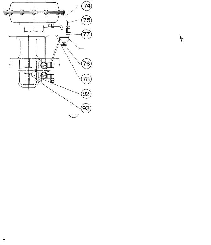
Mounting on 657 and 667 Actuators
During the following mounting procedures, refer to figures 7, 24, and 25 for key number locations. Figure 7 shows keys 69 and 70, 73 through 78, and 82 through 93. Other key numbers are shown in either figure 24 for the 3660 positioner or figure 25 for the 3661 positioner.
1.Determine the positioner mounting configuration from figure 2. The actuator size, actuator travel, and positioner action must be known.
Note
The actuator bench set spring load must be released before removing the stem connector cap screws. Refer to the appropriate actuator instruction manual for this procedure. After installing the positioner and mounting hardware, reset the actuator bench set.
2.Attach the connector bracket (key 87) to the actuator stem connector using washers and cap screws (keys 70 and 69), but do not tighten the screws. Refer to figures 7 and 8 for the proper orientation of the connector bracket
with respect to the actuator stem connector. The face of the stem connector should be perpendicular to the legs of the actuator yoke.
3.Refer to figure 8 for the feedback arm (key 88) location with respect to the connector bracket (key 87). Position the feedback arm so that the pilot shaft (key 19A) will operate correctly in the slot of the feedback arm. For actuator travels between 19 and 30 mm (0.75 and 1.18 inches), position the feedback arm so that the long portion of the feedback arm slot, when fastened to the connector bracket, is closest to the positioner (see figure 8). For travels greater than 30 mm (1.18 inches) reverse the feedback arm so the slot in the feedback arm is opposite the positioner (see figure 8).
4.Attach the feedback arm (key 88) to the connector bracket (key 87) using machine screws, washers and hex nuts (keys 91, 92 and 93), but do not tighten the hex nuts.
5.Unscrew the two machine screws (key 24), and remove the positioner cover (key 21).
6.As shown in figure 5, a thin knockout section is cast across the mounting hole in the housing. Check to make certain that this knockout section has been removed. If the knockout section has not been removed, use a punch to knock it out.
7.Set the actuator at mid travel using a manual loading regulator.
8.Install the stud clamp (key 83) in the mounting bracket (key 82). Place the mounting bracket against the outside of the actuator leg. Attach the two U bolts (key 84) and the mounting bracket to the actuator leg using washers and hex nuts (key 85 and 86), but do not tighten the nuts. Depending on the positioner action, it may be necessary to straddle the travel indicator scale located on the inside of the actuator leg.
Note
Do not install the range spring in the following step. Feedback lever assembly (key 19) installation in the next step is only temporary to permit verifying alignment.
13
3660 and 3661 Positioners |
Instruction Manual |
January 2013 |
D101402X012 |
|
|
Figure 7. Positioner Mounting on Fisher 657 and 667 Actuators
|
|
TO POSITIONER |
|
|
|
667 |
|
OUTPUT |
REGULATOR
NIPPLE MOUNTED
FILTER REGULATOR
SECTION A A
APPLY LUB
41B6744 D
14
 Loading...