


 Loading...


 AC Power


 For Business-Critical Continuity™


 Liebert® GXT2-10000RT208™


 User Manual–10kVA, 60 Hz, 120/208/240V

TABLE OF CONTENTS
IMPORTANT SAFETY INSTRUCTIONS . . . . . . . . . . . . . . . . . . . . . . . . . . . . . . . . . . . . . . . . . . . . . . . .1 1.0 GLOSSARY OF SYMBOLS . . . . . . . . . . . . . . . . . . . . . . . . . . . . . . . . . . . . . . . . . . . . . . . . . .3 2.0 INTRODUCTION AND SYSTEM DESCRIPTION . . . . . . . . . . . . . . . . . . . . . . . . . . . . . . . . . . . . .4
3.0 SYSTEM DESCRIPTION . . . . . . . . . . . . . . . . . . . . . . . . . . . . . . . . . . . . . . . . . . . . . . . . . . . .5
3.1 Transient Voltage Surge Suppression (TVSS) and EMI/RFI Filters. . . . . . . . . . . . . . . . . . . . 5 3.2 Rectifier/Power Factor Correction (PFC) Circuit . . . . . . . . . . . . . . . . . . . . . . . . . . . . . . . . . . . 5 3.3 Inverter . . . . . . . . . . . . . . . . . . . . . . . . . . . . . . . . . . . . . . . . . . . . . . . . . . . . . . . . . . . . . . . . . . . . 5 3.4 Battery Charger . . . . . . . . . . . . . . . . . . . . . . . . . . . . . . . . . . . . . . . . . . . . . . . . . . . . . . . . . . . . . 5 3.5 DC to DC Converter . . . . . . . . . . . . . . . . . . . . . . . . . . . . . . . . . . . . . . . . . . . . . . . . . . . . . . . . . . 6 3.6 Battery . . . . . . . . . . . . . . . . . . . . . . . . . . . . . . . . . . . . . . . . . . . . . . . . . . . . . . . . . . . . . . . . . . . . 6 3.7 Static Bypass . . . . . . . . . . . . . . . . . . . . . . . . . . . . . . . . . . . . . . . . . . . . . . . . . . . . . . . . . . . . . . . 6
4.0 MAJOR COMPONENTS . . . . . . . . . . . . . . . . . . . . . . . . . . . . . . . . . . . . . . . . . . . . . . . . . . . .7
4.1 Main Frame and Electronics . . . . . . . . . . . . . . . . . . . . . . . . . . . . . . . . . . . . . . . . . . . . . . . . . . . 7 4.2 Internal Battery Pack . . . . . . . . . . . . . . . . . . . . . . . . . . . . . . . . . . . . . . . . . . . . . . . . . . . . . . . . 7 4.3 Input/Output Terminal Blocks and Optional Output Distribution . . . . . . . . . . . . . . . . . . . . . 8
5.0 WHAT’S INCLUDED . . . . . . . . . . . . . . . . . . . . . . . . . . . . . . . . . . . . . . . . . . . . . . . . . . . . . . .9
6.0 INSTALLATION AND CONFIGURATION . . . . . . . . . . . . . . . . . . . . . . . . . . . . . . . . . . . . . . . . .10
6.1 Install the Main Cabinet . . . . . . . . . . . . . . . . . . . . . . . . . . . . . . . . . . . . . . . . . . . . . . . . . . . . . 10
6.1.1 Tower UPS Installation . . . . . . . . . . . . . . . . . . . . . . . . . . . . . . . . . . . . . . . . . . . . . . . . . . . . . . . 10 6.1.2 Installing the Adjustable Rack-Mount Kit—Sold Separately . . . . . . . . . . . . . . . . . . . . . . . . . 11
6.2 External Battery Cabinet Installation . . . . . . . . . . . . . . . . . . . . . . . . . . . . . . . . . . . . . . . . . . 13 6.3 Connect Input/Output Power. . . . . . . . . . . . . . . . . . . . . . . . . . . . . . . . . . . . . . . . . . . . . . . . . . 14
6.3.1 Distribution Module Electrical Connections. . . . . . . . . . . . . . . . . . . . . . . . . . . . . . . . . . . . . . . 14 6.3.2 Input & Output Terminal Block Connections. . . . . . . . . . . . . . . . . . . . . . . . . . . . . . . . . . . . . . 15 6.3.3 Add an Output Power Distribution Module—Optional . . . . . . . . . . . . . . . . . . . . . . . . . . . . . . 16
6.4 Install the Internal Battery Packs . . . . . . . . . . . . . . . . . . . . . . . . . . . . . . . . . . . . . . . . . . . . . 17
7.0 INITIAL STARTUP AND ELECTRICAL CHECKS . . . . . . . . . . . . . . . . . . . . . . . . . . . . . . . . . . .18
7.1 Hardwire Input Connections . . . . . . . . . . . . . . . . . . . . . . . . . . . . . . . . . . . . . . . . . . . . . . . . . . 18
7.2 Output Receptacle Distribution Options. . . . . . . . . . . . . . . . . . . . . . . . . . . . . . . . . . . . . . . . . 19
8.0 CONFIGURATION PROGRAM . . . . . . . . . . . . . . . . . . . . . . . . . . . . . . . . . . . . . . . . . . . . . . .20
8.1 Liebert GXT2-10000RT208 Configuration Program Features . . . . . . . . . . . . . . . . . . . . . . . 20
8.2 What You Will Need. . . . . . . . . . . . . . . . . . . . . . . . . . . . . . . . . . . . . . . . . . . . . . . . . . . . . . . . . 20
i

8.3 Configuration Program—Installation . . . . . . . . . . . . . . . . . . . . . . . . . . . . . . . . . . . . . . . . . . . 21 8.4 Establishing Communication Link with the UPS . . . . . . . . . . . . . . . . . . . . . . . . . . . . . . . . . 21 8.5 Configuration Program—Operation . . . . . . . . . . . . . . . . . . . . . . . . . . . . . . . . . . . . . . . . . . . . 22
8.5.1 Read/Confirm UPS Configuration Settings . . . . . . . . . . . . . . . . . . . . . . . . . . . . . . . . . . . . . . . 22 8.5.2 Cancel Without Changing UPS Settings . . . . . . . . . . . . . . . . . . . . . . . . . . . . . . . . . . . . . . . . . 22 8.5.3 Changing UPS Settings . . . . . . . . . . . . . . . . . . . . . . . . . . . . . . . . . . . . . . . . . . . . . . . . . . . . . . . 22 8.5.4 On-Screen Reminders . . . . . . . . . . . . . . . . . . . . . . . . . . . . . . . . . . . . . . . . . . . . . . . . . . . . . . . . 23 8.5.5 Programming Rejected When UPS is Off . . . . . . . . . . . . . . . . . . . . . . . . . . . . . . . . . . . . . . . . . 23
8.6 UPS Tab . . . . . . . . . . . . . . . . . . . . . . . . . . . . . . . . . . . . . . . . . . . . . . . . . . . . . . . . . . . . . . . . . . 24
8.6.1 |
Output Voltage . . . . . . . . . . . . . . . . . . . . . . . . . . . . . . . . . . . . . . . . . . . . . . . . . . . . . . . . . . . . . |
24 |
8.6.2 L-N Reverse Detection—120V UPS Models Only. . . . . . . . . . . . . . . . . . . . . . . . . . . . . . . . . . . |
24 |
|
8.6.3 |
Frequency Selection . . . . . . . . . . . . . . . . . . . . . . . . . . . . . . . . . . . . . . . . . . . . . . . . . . . . . . . . . . |
25 |
8.7 Options Tab. . . . . . . . . . . . . . . . . . . . . . . . . . . . . . . . . . . . . . . . . . . . . . . . . . . . . . . . . . . . . . . . 25
8.8 Options Tab Used With Earlier Liebert GXT2 Models . . . . . . . . . . . . . . . . . . . . . . . . . . . . . 26
8.9 Battery Tab. . . . . . . . . . . . . . . . . . . . . . . . . . . . . . . . . . . . . . . . . . . . . . . . . . . . . . . . . . . . . . . . 27
8.9.1 Low Battery Time Warning . . . . . . . . . . . . . . . . . . . . . . . . . . . . . . . . . . . . . . . . . . . . . . . . . . . . 27
8.9.2 Auto Battery Test Time . . . . . . . . . . . . . . . . . . . . . . . . . . . . . . . . . . . . . . . . . . . . . . . . . . . . . . . 27
8.9.3 Battery Cabinets Number . . . . . . . . . . . . . . . . . . . . . . . . . . . . . . . . . . . . . . . . . . . . . . . . . . . . . 27
8.9.4 Auto Battery Test . . . . . . . . . . . . . . . . . . . . . . . . . . . . . . . . . . . . . . . . . . . . . . . . . . . . . . . . . . . . 27
8.9.5 Auto Restart . . . . . . . . . . . . . . . . . . . . . . . . . . . . . . . . . . . . . . . . . . . . . . . . . . . . . . . . . . . . . . . . 27
8.10 About Tab . . . . . . . . . . . . . . . . . . . . . . . . . . . . . . . . . . . . . . . . . . . . . . . . . . . . . . . . . . . . . . . . . 28
9.0 CONTROLS AND INDICATORS. . . . . . . . . . . . . . . . . . . . . . . . . . . . . . . . . . . . . . . . . . . . . . .29
9.1 ON/Alarm Silence/Battery Test Button . . . . . . . . . . . . . . . . . . . . . . . . . . . . . . . . . . . . . . . . . 29 9.2 OFF/Bypass Button . . . . . . . . . . . . . . . . . . . . . . . . . . . . . . . . . . . . . . . . . . . . . . . . . . . . . . . . . 29 9.3 L1 & L2 Load Level Indicators (Two Rows of Indicators: 4 Green, 1 Amber). . . . . . . . . . . . 30 9.4 Battery Level Indicators (5 Green) . . . . . . . . . . . . . . . . . . . . . . . . . . . . . . . . . . . . . . . . . . . . . 30 9.5 Fault Indicator (Red) . . . . . . . . . . . . . . . . . . . . . . . . . . . . . . . . . . . . . . . . . . . . . . . . . . . . . . . . 30 9.6 Bypass Indicator (Amber) . . . . . . . . . . . . . . . . . . . . . . . . . . . . . . . . . . . . . . . . . . . . . . . . . . . . 30 9.7 UPS ON Indicator (Green). . . . . . . . . . . . . . . . . . . . . . . . . . . . . . . . . . . . . . . . . . . . . . . . . . . . 30 9.8 Battery Indicator (Amber) . . . . . . . . . . . . . . . . . . . . . . . . . . . . . . . . . . . . . . . . . . . . . . . . . . . . 30 9.9 AC Input Indicator (Green) . . . . . . . . . . . . . . . . . . . . . . . . . . . . . . . . . . . . . . . . . . . . . . . . . . . 30
10.0 MODES OF OPERATION. . . . . . . . . . . . . . . . . . . . . . . . . . . . . . . . . . . . . . . . . . . . . . . . . . .31
10.1 Normal Mode Operation. . . . . . . . . . . . . . . . . . . . . . . . . . . . . . . . . . . . . . . . . . . . . . . . . . . . . . 31
10.2 Battery Mode Operation . . . . . . . . . . . . . . . . . . . . . . . . . . . . . . . . . . . . . . . . . . . . . . . . . . . . . 31
10.3 Battery Recharge Operation . . . . . . . . . . . . . . . . . . . . . . . . . . . . . . . . . . . . . . . . . . . . . . . . . . 31
ii

11.0 COMMUNICATIONS . . . . . . . . . . . . . . . . . . . . . . . . . . . . . . . . . . . . . . . . . . . . . . . . . . . . . .32
11.1 Communications Interface Port. . . . . . . . . . . . . . . . . . . . . . . . . . . . . . . . . . . . . . . . . . . . . . . . 32
11.1.1 DB-9 Interface Port . . . . . . . . . . . . . . . . . . . . . . . . . . . . . . . . . . . . . . . . . . . . . . . . . . . . . . . . . . 32 11.1.2 Communications—Liebert SNMP/OCWEBCARD SNMP Adapter . . . . . . . . . . . . . . . . . . . . . 33
11.2 Pin 4 - Remote Shutdown on Battery . . . . . . . . . . . . . . . . . . . . . . . . . . . . . . . . . . . . . . . . . . . 33 11.3 UPS Intelligent Communications . . . . . . . . . . . . . . . . . . . . . . . . . . . . . . . . . . . . . . . . . . . . . . 33 11.4 Remote Emergency Power Off . . . . . . . . . . . . . . . . . . . . . . . . . . . . . . . . . . . . . . . . . . . . . . . . . 34
12.0 MAINTENANCE . . . . . . . . . . . . . . . . . . . . . . . . . . . . . . . . . . . . . . . . . . . . . . . . . . . . . . . . .35
12.1 Battery Replacement . . . . . . . . . . . . . . . . . . . . . . . . . . . . . . . . . . . . . . . . . . . . . . . . . . . . . . . . 35
12.1.1 Internal Battery Replacement Procedures . . . . . . . . . . . . . . . . . . . . . . . . . . . . . . . . . . . . . . . . 35
12.2 UPS Power Module Replacement . . . . . . . . . . . . . . . . . . . . . . . . . . . . . . . . . . . . . . . . . . . . . . 36
13.0 TROUBLESHOOTING . . . . . . . . . . . . . . . . . . . . . . . . . . . . . . . . . . . . . . . . . . . . . . . . . . . . .38
13.1 Auto-Learning Battery Run Times . . . . . . . . . . . . . . . . . . . . . . . . . . . . . . . . . . . . . . . . . . . . . 43
14.0 SPECIFICATIONS . . . . . . . . . . . . . . . . . . . . . . . . . . . . . . . . . . . . . . . . . . . . . . . . . . . . . . . .44
14.1 Product Warranty Registration . . . . . . . . . . . . . . . . . . . . . . . . . . . . . . . . . . . . . . . . . . . . . . . . 47
iii

FIGURES
Figure 1 10 kVA Dual Inverter Liebert GXT2-10000RT208, front and rear views . . . . . . . . . . . . . . . . . . . . 7 Figure 2 Internal battery pack and connector . . . . . . . . . . . . . . . . . . . . . . . . . . . . . . . . . . . . . . . . . . . . . . . . . 7 Figure 3 Hardwire terminal blocks. . . . . . . . . . . . . . . . . . . . . . . . . . . . . . . . . . . . . . . . . . . . . . . . . . . . . . . . . . 8 Figure 4 Optional output distribution modules . . . . . . . . . . . . . . . . . . . . . . . . . . . . . . . . . . . . . . . . . . . . . . . . 8 Figure 5 Support base and spacers . . . . . . . . . . . . . . . . . . . . . . . . . . . . . . . . . . . . . . . . . . . . . . . . . . . . . . . . . 10 Figure 6 60A branch circuit breaker connection diagram . . . . . . . . . . . . . . . . . . . . . . . . . . . . . . . . . . . . . . . 14 Figure 7 Hardwire terminal connections . . . . . . . . . . . . . . . . . . . . . . . . . . . . . . . . . . . . . . . . . . . . . . . . . . . . 19 Figure 8 Control and indicator overlays, vertical and horizontal . . . . . . . . . . . . . . . . . . . . . . . . . . . . . . . . . 29 Figure 9 REPO switch connections . . . . . . . . . . . . . . . . . . . . . . . . . . . . . . . . . . . . . . . . . . . . . . . . . . . . . . . . . 34 Figure 10 UPS back panel—control location . . . . . . . . . . . . . . . . . . . . . . . . . . . . . . . . . . . . . . . . . . . . . . . . . . 37 Figure 11 Power module replacement . . . . . . . . . . . . . . . . . . . . . . . . . . . . . . . . . . . . . . . . . . . . . . . . . . . . . . . 37
TABLES
Table 1 Electrical requirements . . . . . . . . . . . . . . . . . . . . . . . . . . . . . . . . . . . . . . . . . . . . . . . . . . . . . . . . . . 15 Table 2 DB-9 pin assignment . . . . . . . . . . . . . . . . . . . . . . . . . . . . . . . . . . . . . . . . . . . . . . . . . . . . . . . . . . . . 32 Table 3 Fault indicators. . . . . . . . . . . . . . . . . . . . . . . . . . . . . . . . . . . . . . . . . . . . . . . . . . . . . . . . . . . . . . . . . 38 Table 4 Alarm conditions . . . . . . . . . . . . . . . . . . . . . . . . . . . . . . . . . . . . . . . . . . . . . . . . . . . . . . . . . . . . . . . . 39 Table 5 Troubleshooting guide . . . . . . . . . . . . . . . . . . . . . . . . . . . . . . . . . . . . . . . . . . . . . . . . . . . . . . . . . . . 40 Table 6 Battery run times . . . . . . . . . . . . . . . . . . . . . . . . . . . . . . . . . . . . . . . . . . . . . . . . . . . . . . . . . . . . . . . 42 Table 7 UPS specifications. . . . . . . . . . . . . . . . . . . . . . . . . . . . . . . . . . . . . . . . . . . . . . . . . . . . . . . . . . . . . . . 44 Table 8 Battery specifications . . . . . . . . . . . . . . . . . . . . . . . . . . . . . . . . . . . . . . . . . . . . . . . . . . . . . . . . . . . . 45 Table 9 Optional output distribution specifications—PD-101 . . . . . . . . . . . . . . . . . . . . . . . . . . . . . . . . . . . 45 Table 10 Optional output distribution specifications—PD-102 . . . . . . . . . . . . . . . . . . . . . . . . . . . . . . . . . . . 46 Table 11 Optional output distribution specifications—PD-103 . . . . . . . . . . . . . . . . . . . . . . . . . . . . . . . . . . . 46 Table 12 Replacement 10kVA power module specifications . . . . . . . . . . . . . . . . . . . . . . . . . . . . . . . . . . . . . 46 Table 13 External battery cabinet specifications . . . . . . . . . . . . . . . . . . . . . . . . . . . . . . . . . . . . . . . . . . . . . . 47
iv

IMPORTANT SAFETY INSTRUCTIONS
! WARNING
Opening or removing the cover may expose you to lethal voltages within this unit even when it is apparently not operating and the input wiring is disconnected from the electrical source. Observe all cautions and warnings in this manual. Failure to do so may result in serious injury or death. Refer all UPS and battery service to qualified service personnel. Do not attempt to service this product yourself. Never work alone.
SAVE THESE INSTRUCTIONS
This manual contains important safety instructions. Read all safety, installation and operating instructions before operating the Uninterruptible Power System (UPS). Adhere to all warnings on the unit and in this manual. Follow all operating and user instructions. Individuals without previous training can install and operate this equipment.
It is not intended for use with life support and other designated critical devices. Maximum load must not exceed that shown on the UPS rating label. The UPS is designed for data processing equipment. If uncertain, consult your local dealer or Liebert representative.
This UPS is designed for use on a properly grounded (earthed), 100/200, 110/220, 115/230, 120/208, 120/240 or 127/220 VAC, 50 Hz or 60 Hz supply. The factory default setting is 120/208 VAC, 60 Hz. Installation instructions and warning notices are located in this manual.
This UPS is only for use with a four-wire input (L1, L2, N, G).
This UPS MAY NOT be used with a three-wire, single-phase utility source (L1, N, G).
ELECTROMAGNETIC COMPATIBILITY—The Liebert GXT2-10000RT208 Series complies with the limits for a CLASS A DIGITAL DEVICE, PURSUANT TO Part 15 of FCC rules. Operation is subject to the following two conditions: (1) This device may not cause harmful interference and (2) this device must accept any interference received, including interference that may cause undesired operation. Operating this device in a residential area is likely to cause harmful interference that users must correct at their own expense.
Operate the UPS in an indoor environment only in an ambient temperature range of 32°F to +104°F (0°C to +40°C). Install it in a clean environment, free from conductive contaminants, moisture, flammable liquids, gases and corrosive substances.
This UPS contains no user serviceable parts except the internal battery pack. The Off/Bypass push button does not electrically isolate internal parts. Under no circumstances attempt to gain access internally other than to replace the batteries due to risk of electric shock or burn. Do not continue to use the UPS if the front panel indications are not in accordance with these operating instructions or if the UPS performance alters in use. Refer all faults to your local dealer, Liebert representative or the Liebert Worldwide Support Group.
Servicing of batteries should be performed or supervised by personnel knowledgeable of batteries and the required precautions. Keep unauthorized personnel away from the batteries. PROPER DISPOSAL OF BATTERIES IS REQUIRED. REFER TO YOUR LOCAL LAWS AND REGULATIONS FOR BATTERY DISPOSAL REQUIREMENTS.
Never block or insert any object into the ventilation holes or other openings of the UPS.
DO NOT CONNECT equipment that could overload the UPS or demand half-wave rectification from the UPS, for example: electric drills, vacuum cleaners, laser printers, hair dryers or any other appliance using half-wave rectification.
Storing magnetic media on top of the UPS may result in data loss or corruption.
Turn the UPS off and isolate the UPS before cleaning; use only a soft cloth, never liquid or aerosol cleaners. Keep the front and rear vents free of dust accumulation that could restrict airflow.
1

When replacing batteries, replace with the same Liebert authorized replacement battery kits. When replacing the power module, replace it with the same Liebert authorized replacement power module kit.
! CAUTION
Do not dispose of battery or batteries in a fire. The battery may explode.
Do not open or mutilate the battery or batteries. Released electrolyte is harmful to skin and eyes. It is toxic.
! CAUTION
A battery can present a risk of electrical shock and high short circuit current. The following precautions should be observed when working on batteries:
•Remove watches, rings and other metal objects.
•Use tools with insulated handles.
•Wear rubber gloves and boots.
•Do not lay tools or metal parts on top of batteries.
•Disconnect charging source prior to connecting or disconnecting battery terminals.
•Determine if the battery is inadvertently grounded. If inadvertently grounded, remove source of ground. Contact with any part of a grounded battery can result in electrical shock. The likelihood of such shock will be reduced if such grounds are removed during installation and maintenance (applicable to a UPS and a remote battery supply not having a grounded supply circuit).
2
Glossary of Symbols
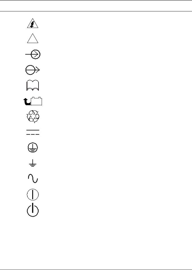
1.0GLOSSARY OF SYMBOLS
Risk of electrical shock
!Indicates caution followed by important instructions
AC input
AC output
 i
i
Requests the user to consult the manual
- |
+ |
Indicates the unit contains a valve-regulated lead acid battery |
|
PbH2SO4 |
|||
|
|||
RRecycle
DC voltage
Equipment grounding conductor
Bonded to ground
AC voltage
ON/Alarm Silence/Battery Test
OFF/Bypass
3

Introduction and System Description
2.0INTRODUCTION AND SYSTEM DESCRIPTION
Congratulations on your choice of the Liebert GXT2-10000RT208 Uninterruptible Power Supply (UPS). It provides conditioned power to microcomputers and other sensitive electronic equipment.
Upon generation, AC power is clean and stable. However, during transmission and distribution it is subject to voltage sags, spikes or complete power failure that may interrupt computer operations, cause data loss or even damage equipment. The Liebert GXT2-10000RT208 protects equipment from these disturbances.
The Liebert GXT2-10000RT208 is a compact, on-line UPS. An on-line UPS continuously conditions and regulates its output voltage whether utility power is present or not. It supplies connected equipment with clean sinewave power. Sensitive electronic equipment operates best from sinewave power.
For ease of use, the Liebert GXT2-10000RT208 features a light-emitting diode (LED) display to indicate both load percentage and battery capacity. It also provides self-diagnostic tests, a combination ON/Alarm Silence/Battery Test button, a Standby button, user configurable program and two levels of alarms when the unit is operating on battery.
The Liebert GXT2-10000RT208 has an interface port for communication between the UPS and a network server or other computer systems. This port provides detailed operating information including voltages, currents and alarm status to the host system when used in conjunction with Liebert’s MultiLink™ software. Liebert MultiLink software can also control UPS operation remotely.
4
System Description
3.0SYSTEM DESCRIPTION
Input |
Output |
|
|
|
Static |
|
|
|
|
|
Bypass |
|
|
L1 |
|
|
|
L1 |
|
TVSS & |
|
|
|
||
L2 |
Rectifier |
|
L2 |
||
N |
EMI/RFI |
Inverter |
N |
||
Filters |
/PFC |
||||
|
|
||||
|
|
|
DC to DC |
|
|
|
|
|
Converter |
|
Battery |
Battery |
Charger |
G  G
G
3.1Transient Voltage Surge Suppression (TVSS) and EMI/RFI Filters
These UPS components provide surge protection and filter both electromagnetic interference (EMI) and radio frequency interference (RFI). They minimize any surges or interference present in the utility line and keep the sensitive equipment protected.
3.2Rectifier/Power Factor Correction (PFC) Circuit
In normal operation, the rectifier/power factor correction (PFC) circuit converts utility AC power to regulated DC power for use by the inverter while ensuring that the waveshape of the input current used by the UPS is near ideal. Extracting this sinewave input current achieves two objectives:
•The utility power is used as efficiently as possible by the UPS.
•The amount of distortion reflected on the utility is reduced.
This results in cleaner power being available to other devices in the building not being protected by the Liebert GXT2-10000RT208.
3.3Inverter
In normal operation, the inverter utilizes the DC output of the power factor correction circuit and inverts it into precise, regulated sinewave AC power. Upon a utility power failure, the inverter receives energy from the battery through the DC to DC converter. In both modes of operation, the UPS inverter is on-line and continuously generating clean, precise, regulated AC output power.
3.4Battery Charger
The battery charger utilizes energy from the utility power and precisely regulates it to continuously float charge the batteries. The batteries are being charged whenever the Liebert GXT2-10000RT208 is plugged in, even when the UPS is not turned on.
5

System Description
3.5DC to DC Converter
The DC-to-DC converter utilizes energy from the battery system and raises the DC voltage to the optimum operating voltage for the inverter. This allows the inverter to operate continuously at its optimum efficiency and voltage, thus increasing reliability.
3.6Battery
The Liebert GXT2-10000RT208 utilizes valve-regulated, nonspillable, flame retardant, lead acid batteries. To maintain battery design life, operate the UPS in an ambient temperature of 68°F to 77°F (20°C to 25°C). Optional external battery cabinets are available to extend battery run times.
3.7Static Bypass
The Liebert GXT2-10000RT208 provides an alternate path for utility power to the connected load in the unlikely event of a UPS malfunction. Should the UPS have an overload, overtemperature or UPS failure condition, the UPS automatically transfers the connected load to bypass. Bypass operation is indicated by an audible alarm and illuminated amber Bypass indicator (other indicators may be illuminated to indicate the diagnosed problem).
The user may manually transfer the connected load from the inverter to bypass by pressing the Standby button once.
NOTE
The bypass power path does NOT protect the connected equipment from disturbances on the utility supply.
6
Major Components
4.0MAJOR COMPONENTS
The Liebert GXT2-10000RT208 is composed of three major assemblies to provide easier handling, installation and versatility.
4.1Main Frame and Electronics
This 6U cabinet arrives without internal batteries to lighten the UPS for easier installation. Once the cabinet has been placed in its final floor or rack position, the internal batteries may be installed. The UPS is shipped with standard hardwire terminal blocks for input and output connections.
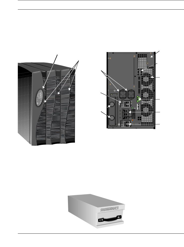
Figure 1 10 kVA Dual Inverter Liebert GXT2-10000RT208, front and rear views
Status Indicators
and Controls
FRONT VIEW |
Front Bezels, 3 |
|
External Battery
Connectors
!  UPStationGXT


Output
Circuit
Breaker
Hardwire 
Knockouts
Battery Compartment
(behind center and right bezels); Internal Battery Pack is shipped loose
(see Section 4.2)
REAR VIEW |
Liebert |
|
IntelliSlot® Port |
|
DB-9 |
|
Communications |
|
Ports, 2 |
|
Cooling Fan, |
|
1 of 3 |
REPO
Switch
UPS/Bypass
Breaker
Input Circuit
Breaker
4.2Internal Battery Pack
The center front bezel may be pulled forward and removed to reveal the battery access plate. The cover plate can be removed by extracting the three screws at the top of the cover plate and lifting the plate off. The two internal battery packs are compact assemblies ready to slide into the battery compartment after the front battery access plate has been removed. Electrical connection is made with the two slotted battery connectors.
Figure 2 Internal battery pack and connector
Battery connector on front of battery pack
7
Major Components
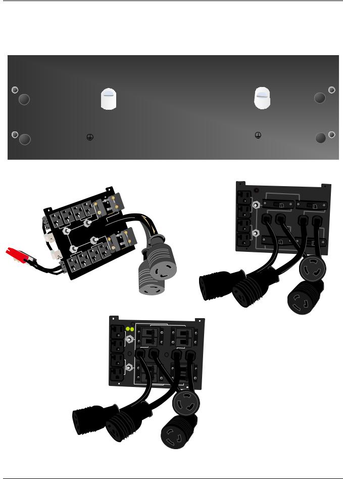
4.3Input/Output Terminal Blocks and Optional Output Distribution
The UPS is shipped with hardwire terminal blocks. For maximum flexibility, additional distribution options are available that provide the benefit of output receptacle convenience.
Figure 3 Hardwire terminal blocks
Figure 4 Optional output distribution modules
PD-101
Power Distribution Option with Internal Connector
OUTPUT BREAKER 30A 250V-/T
OUTPUT L1
H-POTED |
QC |
- |
|
O |
|
- |
|
O |
PASS |
PASS |
ON |
|
30A |
-HYMAAAG |
ON |
|
30A |
|
HYMAAAG- |
O |
O |
|||||
|
|
|
|
|
|
|
|
|
120A 125V |
|
|
|
|
|
|
|
|
PUSH TO |
|
|
|
|
|
|
|
|
RESTART |
|
|
|
|
|
|
|
|
120A 125V |
|
|
|
|
|
|
|
|
PUSH TO |
|
|
|
|
|
|
|
|
RESTART |
- |
|
|
|
|
|
|
|
|
HY-MAAAG |
O |
O |
-HYMAAAG |
- |
|
O |
|
|
ON |
30A |
ON |
O |
30A |
|||
 OUTPUT L2
OUTPUT BREAKER 20A 250V~/T |
PD~102 |
OUTPUT L1 |
OUTPUT BREAKER 20A 250V~/T |
OUTPUT BREAKER 20A 250V~/T |
|
||
120A 125V |
|
|
PUSH TO |
|
|
RESTART |
|
|
120A 125V |
|
|
PUSH TO |
|
|
RESTART |
|
|
|
OUTPUT BREAKER 20A 250V~/T |
OUTPUT BREAKER 20A 250V~/T |
|
|
|
OUTPUT L2 |
|
PD~102 |
PD-102
Power Distribution Option
PD-103
Power Distribution Option
8
What’s Included
5.0WHAT’S INCLUDED
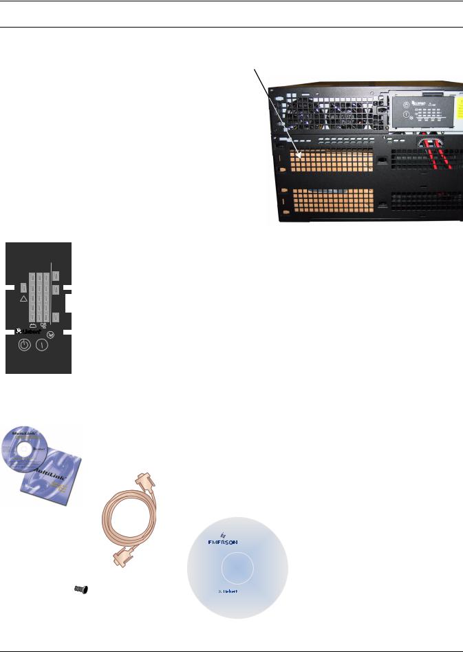
The Liebert GXT2-10000RT208 is shipped with these items:
•UPS user manual
•Vertical display overlay
•Front bezels - 3
•Top bezels - 3
•Battery cover grille
•Power Module cover grille
•Battery pack brackets - 2
•Liebert MultiLink software CD
•Liebert MultiLink serial cable, 10 ft. (3m)
•Rack mount handles
•Support bases - 2
•Mounting hardware
•Configuration program compact disk
•Ferrite beads - 2
Box containing accessories is shipped in the UPS’ battery compartment
L1 L2
BYPASS
UPS ON ! 
BATTERY
AC INPUT - +
UPStation GXT
Front bezels (2)
Vertical display overlay
Battery brackets
Liebert MultiLink
software CD
Liebert
MultiLink serial cable 10 ft (3m)
Mounting hardware
Rack-mount handles
www.liebert.com
GXT2U™ Configuration Program
For use with Liebert GXT2U model
UPS systems.
Version 1.6
For Windows XP, 2000 NT, 98
Configuration
compact disk
Side bezels for rack
Top bezels for tower
Battery cover
Support base with spacers
Ferrite beads (2)
9
Installation and Configuration
6.0INSTALLATION AND CONFIGURATION
This section includes instructions on how to install, configure and perform initial electrical checks of your UPS installation.
DO NOT attempt to start the UPS, turn on any circuit breaker or energize the input power until instructed to do so in 7.0 - Initial Startup and Electrical Checks.
Visually inspect the UPS for freight damage. Report damage to the carrier and your local dealer or Liebert representative.
! CAUTION
The UPS is heavy (see 14.0 - Specifications). Take proper precautions when lifting or moving it.
Install the UPS indoors in a controlled environment, where it cannot be accidentally turned off. Place it in an area of unrestricted airflow around the unit, away from water, flammable liquids, gases, corrosives and other conductive contaminants. Maintain a minimum clearance of 4" (100mm) in the front and rear of the UPS. Maintain an ambient temperature range of 32°F to 104°F (0°C to 40°C).
NOTE
UPS operation in sustained temperatures above 77°F (25°C) reduces battery life.
6.1Install the Main Cabinet
The Liebert GXT2-10000RT208 may be installed either as a tower unit or in a rack, depending on available space and use considerations. Determine the type of installation and follow the appropriate instructions in either 6.1.1 - Tower UPS Installation or 6.1.2 - Installing the Adjustable RackMount Kit—Sold Separately.
6.1.1Tower UPS Installation
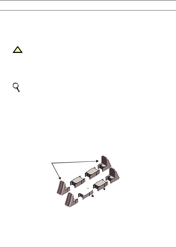
When using the Liebert GXT2-10000RT208 in a tower configuration, use the included support base (shown below, left) to stabilize the UPS.
If any external battery cabinets are added, they will include spacers to accommodate the additional cabinets (shown below, right).
Figure 5 Support base and spacers
End Bases

 Spacers
Attach Bezels to Top
When used as a tower, the Liebert GXT2-10000RT208 requires bezels attached to the top. To connect the bezels:
1.Position the UPS so that the battery compartments are on the right side.
2.Attach the top bezels by placing them on the mounting holes and sliding them toward the rear of the UPS.
10
Installation and Configuration
6.1.2Installing the Adjustable Rack-Mount Kit—Sold Separately
This kit contains parts needed to mount several different models of UPS and external battery cabinets into EIA310-D standard four-post racks that are 18-32" deep (457-813mm). The weight limit per pair of adjustable rack-mounting brackets is 200 pounds (91 kg).
Liebert rack-mount bracket kit, part # RMKIT18-32, includes:
Item |
Quantity |
|
|
Rear bracket members |
2 |
|
|
Front bracket members |
2 |
|
|
Inner bracket members |
2 |
|
|
M4 x 8mm machine screws |
16 |
|
|
M4 locking hex nuts |
8 |
|
|
M5 x 16 mm machine screws |
12 |
|
|
Grease packet. |
1 |
|
|
Tools needed for installation are:
•one Phillips screwdriver
•one 7mm wrench
The adjustable rack-mounting brackets feature retaining latches to prevent users from inadvertently sliding the UPS or battery cabinet out of the rack.
To install the rack mount brackets:
1.Unpack two (2) rack-mounting bracket assemblies and mounting hardware from this kit. Bracket assemblies are interchangeable between left-hand or right-hand.
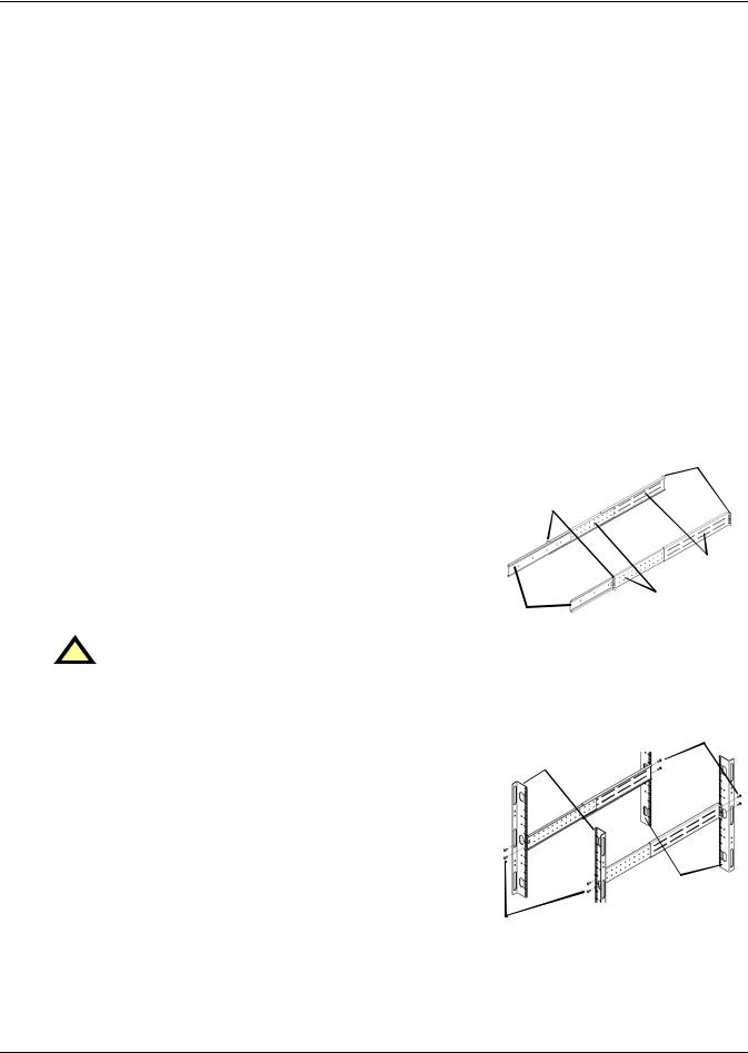
Remove inner member of each bracket assembly as shown in at right by extending it to its outermost position, depressing the retaining latch and then pulling the inner member out of the bracket assembly.
2.Determine the height position inside the rack enclosure where you want to mount the UPS or battery cabinet.
! CAUTION
Reduce the risk of tipping the rack enclosure by placing the UPS or battery cabinet in the lowest possible rack position.
Return flanges
Retaining
Latches
|
Front |
Inner |
members |
members |
|
3.Install the rear member of each bracket assembly into rack enclosure with two (2) M5 screws provided in this kit (see figure at right). The return flanges on the bracket assembly fit to the inside of rack mounting rails. Insert screws loosely (finger-tight) into the top and bottom holes of the return flange on the rear member. Extend the bracket assembly by sliding the front member forward until it touches the front rack mounting rail. Insert two (2) M5 screws loosely (fingertight) into top and bottom holes of the return flange on each front member. Make sure bracket assemblies are at the same mounting height on all four (4) rack mounting rails.
Front rack mounting rails
M5 screws
M5 screws
Rear rack mounting rails
11
Loading...