


Fisher 655
Instruction Manual
D100305X012
Fisherr 655 and 655R Actuators
for Self‐Operated Control
655 and 655R Actuators
December 2010
Contents
Introduction 1.................................
Scope of Manual 1.............................
Description 2.................................
Specifications 2...............................
Installation 2...................................
Actuator Mounting 3...........................
Loading Connections 7.........................
Startup 7......................................
Startup for Pressure‐Reducing Service 7...........
Startup for Pressure‐Relief Service 7..............
Adjustment for Pressure‐Reducing or
Pressure‐Relief Service 8.....................
Shutdown 8...................................
Maintenance 8.................................
Actuator 9...................................
Top‐Mounted Handwheel 12....................
Parts Ordering 14...............................
Parts List 14...................................
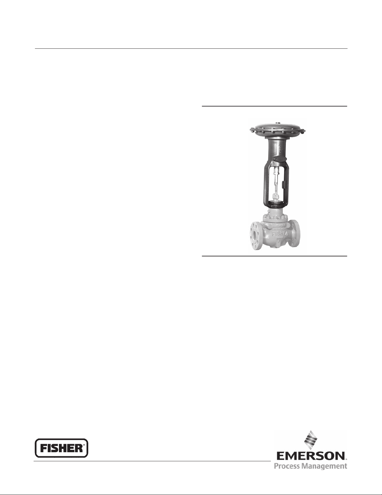
Figure 1. Fisher 655‐ED Pressure‐Reducing Valve
W0466‐1
Introduction
Scope of Manual
This instruction manual provides installation, adjustment, maintenance, and parts ordering for the Fisher 655 and
655R actuators and the top‐mounted handwheel. Refer to separate instruction manuals for information about valves
and accessories used with these actuators.
Do not install, operate, or maintain 655 or 655R actuators without being fully trained and qualified in valve, actuator,
and accessory installation, operation and maintenance. To avoid personal injury or property damage, it is important to
carefully read, understand, and follow all the contents of this manual, including all safety cautions and warnings. If you
have any questions about these instructions, contact your Emerson Process Management sales office before
proceeding.
www.Fisher.com
655 and 655R Actuators
December 2010
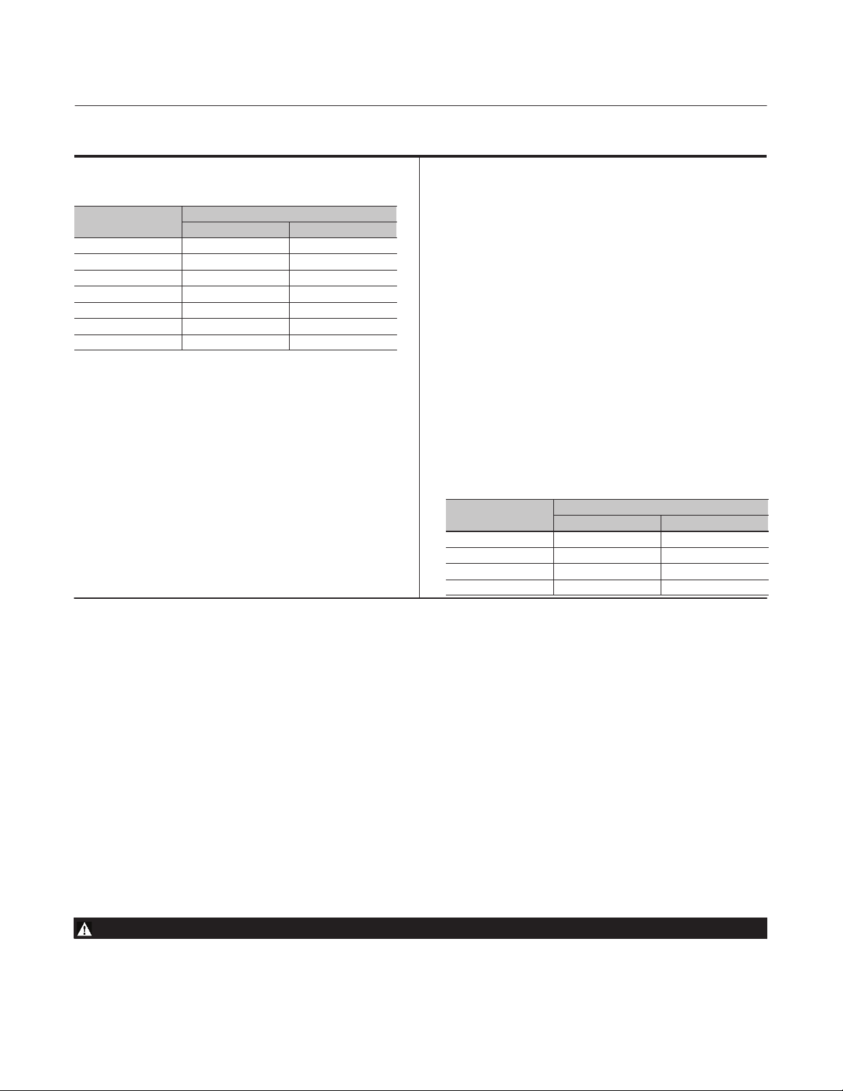
Table 1. Specifications
Instruction Manual
D100305X012
Actuator Sizes and Maximum Casing Pressures
ACTUATOR
SIZE
3A, 4A 17.2 250
3B, 4B 12.1 175
32, 42 6.9 100
33, 43 4.5 65
34, 44 3.1 45
35, 45 2.1 30
36, 46 1.0 15
MAXIMUM CASING PRESSURE
Bar Psig
Actuator Pressure Setting Ranges
See table 2
Actuator Yoke Boss and Valve Stem Connection
Diameters
Sizes 3A through 36: 54 mm (2‐1/8 inch) yoke boss
with 9.5 mm (3/8 inch) stem connection
Sizes 4A through 46: 71 mm (2‐13/16 inch) yoke boss
with 12.7 mm (1/2 inch) stem connection
Maximum Travel
Sizes 3A and 4A: 11 mm (0.4375 inch) plus
3 mm (0.125 inch) for seating
All Other Sizes: 19 mm (0.75 inch) plus 3 mm (0.125
inch) for seating
Effective Diaphragm Area
See table 3
Spring Rate
See key 6 in the parts list section
Temperature Capabilities
-29 to 82_C (-20 to 180_F) with standard diaphragm
material. For the fluid and temperature capabilities of
nonstandard diaphragm materials, consult your
Emerson Process Management sales office
Casing Pressure Connections
1/2 NPT internal
Approximate Weights
ACTUATOR
SIZE
3A, 3B, 32, 33 20 45
34, 35, 36 23 50
4A, 4B, 42, 43 29 65
44, 45, 46 34 75
APPROXIMATE WEIGHT
Kg Lb
Description
655 and 655R actuators (figure 1) are pressure‐actuated, spring‐and‐diaphragm actuators used in conjunction with
various valves to provide control for a wide variety of pressure regulation applications. 655 actuators are used for
pressure‐reducing service when mounted on push‐down‐to‐close valves such as the Fisher ED and ET valves. 655R
actuators are used for pressure‐relief service when mounted on push‐down‐to‐open valves such as the Fisher EDR and
ETR valves. Both types are self‐operated and direct‐acting; that is, increasing pressure in the diaphragm casing forces
the actuator stem downward, and decreasing the pressure allows the actuator spring to lift the actuator stem upward.
Specifications
Specifications for the 655 and 655R actuators are shown in table 1. Information for a specific actuator is also found on
the nameplate of that actuator.
Installation
WARNING
To avoid personal injury or property damage caused by bursting of pressure‐retaining parts, be certain the service
conditions do not exceed the casing pressure limits listed in table 1. Use pressure‐limiting or pressure‐relieving devices to
prevent service conditions from exceeding these limits.
2

Instruction Manual
D100305X012
Always wear protective gloves, clothing, and eyewear when performing any installation operations to avoid personal
injury.
Check with your process or safety engineer for any additional measures that must be taken to protect against process
media.
If installing into an existing application, also refer to the WARNING at the beginning of the Maintenance section in this
instruction manual.
655 and 655R Actuators
December 2010
655 and 655R actuators are normally shipped mounted on a valve. Refer to the appropriate valve instruction manual
when installing the valve in the pipeline. If the actuator is shipped separately or if it is necessary to mount the actuator
on the valve, perform the procedures described in the Actuator Mounting portion of this section.
CAUTION
To avoid premature wear of the diaphragm due to debris in the pressure line to the diaphragm, install a strainer in the
pipeline ahead of the regulator or relief valve.
Before installing the actuator, inspect it for any damage. Also, keep any adjacent piping clean and free of pipe scale or
other debris that could possibly disrupt service. It is recommended that a strainer be installed in the pipeline ahead of
the regulator or relief valve to protect it while in service. And a conventional three‐valve bypass (see figure 2) should
be placed around the regulator or relief valve to permit continuous operation when it is being installed or repaired.
Actuator Mounting
The actuator may be installed either above or below the pipeline.
CAUTION
In steam service applications, avoid premature wear of the diaphragm, due to high temperature steam, by installing the
valve with the actuator positioned below the pipeline.
If the regulator or relief valve is to be used for steam service, the valve should be installed with the actuator positioned
below the pipeline, and the control line should be sloped down toward the diaphragm casing. This is to ensure that
any forming condensate will maintain a water seal to protect the diaphragm.
The following procedure describes how to mount the actuator on either a push‐down‐to‐close or a
push‐down‐to‐open valve so that the actuator stem and valve stem thread engagement will allow full travel and
proper shutoff. Refer to figure 3 for actuator mounting components. Key numbers refer to figure 4 unless otherwise
stated.
1. Turn the adjusting screw (key 10) into the yoke (key 7) to force the diaphragm (key 2) and diaphragm plate (key 4)
against the upper diaphragm casing (key 1).
2. Perform the following steps as appropriate for either push‐down‐to‐close or push‐down‐to‐open valve action.
CAUTION
In the following procedures, do not rotate the valve plug while it is seated since this may cause damage to the seating
surfaces and thereby allow excessive leakage. Also, during travel adjustment, use tools carefully to avoid damaging the
valve plug stem. A damaged stem could cut the packing and allow leakage.
3

655 and 655R Actuators
December 2010
Instruction Manual
D100305X012
For Push‐Down‐To‐Close Valves:
a. Place the actuator part way over the valve stem. Then, place the yoke locknut over the valve stem, and slide the
travel indicator disk (key 11, if used) on top of the hex nuts (key 12).
b. Set the actuator onto the valve body. The length of the valve stem will prevent the actuator yoke (key 7) from
sitting on the bonnet properly. Measure the distance from the bottom of the actuator yoke to the mating
shoulder on the bonnet, and then add the valve plug travel to this measurement.
c. Raise the actuator so the valve plug can be lifted off the seat ring.
Note
Either turn the actuator, or tighten the hex nuts together, and use a wrench on the hex nuts to turn the valve plug and stem
assembly.
Thread the valve stem into the actuator stem the distance measured in the previous step.
d. Lower the actuator onto the valve body bonnet, and tighten the yoke locknut.
e. Connect the pressure control lines as described in the Loading Connection portion of this section.
f. Stroke the actuator, and measure the stem movement to check travel. If the movement is more than full travel,
turn the valve stem out of the actuator stem the amount of over‐travel. If movement is less than full travel, turn
the valve stem into the actuator stem the amount of under‐travel.
For Push‐Down‐To‐Open Valves:
a. Place the actuator, yoke locknut, and travel indicator disk (key 11, if used) over the valve stem. Support the
actuator above the valve body so the actuator stem and valve stem do not contact when the valve plug is seated.
b. Connect the pressure control lines as described in the Loading Connection portion of this section.
c. Move the valve plug, by hand, from the seated to the open position, and make sure that valve stem movement
corresponds to the desired travel.
d. Stroke the actuator until the diaphragm plate (key 4) contacts the down travel stop (see
figure 3).
e. With the valve plug positioned as described in step c above, lower the actuator until the actuator stem contacts
the valve stem, and measure the distance from the bottom of the actuator yoke to the mating shoulder on the
bonnet.
f. Thread the valve stem into the actuator stem until the thread engagement is equal to the distance measured in
the previous step. Tighten the hex nuts (key 12) together, and use a wrench to turn the valve plug and stem
assembly.
g. Lower the actuator onto the valve body bonnet, and tighten the yoke locknut.
h. Stroke the actuator, and measure the stem movement to check travel. If the movement is more than full travel,
turn the valve stem into the actuator stem the amount of over‐travel. If the movement is less than full travel,
turn the valve stem out of the actuator stem the amount of under‐travel.
4

Instruction Manual
D100305X012
655 and 655R Actuators
December 2010
Table 2. Actuator Pressure‐Setting Ranges
ACTUA‐
TOR
SIZE
3A, 4A
3B, 4B
32, 42
33, 43
1. Effects of packing box friction, unbalance, and weight of valve plug not considered in calculations.
SPRING PART
NUMBER
1E792427082 5.4 78 12.0 174 4.5 65 10.1 146
1F714327092 3.0 44 9.3 135 3.0 43 8.2 119 1E795427082 0.8 11 1.6 23 0.6 9.0 1.3 19
1F176927092 2.2 32 6.6 96 2.6 37 5.9 85
1F176827092 1.8 26 5.4 78 2.3 34 5.2 75 1F714327092 0.3 5.0 1.1 16 0.3 5.0 0.9 13
1F176727032 1.3 19 4.1 59 1.4 20 3.9 57 1F176927092 0.3 3.8 0.8 11 0.3 4.0 0.7 10
1E793327082 3.4 50 7.4 107 3.0 43 4.4 64 1F176827092 0.2 2.8 0.6 8.5 0.1 2.0 0.6 8.5
3B
1E795427082 2.9 42 6.3 92 2.4 35 4.4 64
1E793327082 3.4 50 7.4 107 3.0 43 6.1 89 1E795427082 0.5 7.0 1.0 15 0.4 5.5 0.8 11
4B
1E795427082 2.9 42 6.3 92 2.4 35 5.3 77
1E792427082 2.4 35 5.4 78 2.0 29 4.4 64 1E795427082 0.5 7.0 1.0 15 0.4 5.5 0.9 13
1F714327092 1.4 20 4.1 60 1.3 19 3.7 53
1F176927092 1.0 14 3.0 43 1.2 17 2.6 38 1F714327092 0.2 3.3 0.7 10 0.2 3.2 0.6 9.0
1E793327082 2.2 32 4.5 65 1.8 26 2.6 38 1F176927092 0.2 2.4 0.5 7.2 0.2 2.8 0.4 6.3
32
1E795427082 1.8 26 3.8 55 1.5 22 2.6 38 1F176827092 0.1 2.0 0.4 5.9 0.2 2.5 0.4 5.5
1E793327082 2.2 32 4.5 65 1.8 26 3.7 53 1F176727032 0.1 1.5 0.3 4.4 0.1 1.5 0.3 4.2
42
1E795427082 1.8 26 3.8 55 1.5 22 3.1 45 1F714427112 0.07 1.0 0.2 2.9 0.09 1.3 0.2 2.8
1E792427082 1.5 22 3.2 47 1.2 18 2.6 38
1F714327092 0.8 12 2.5 36 0.8 12 2.1 31 1E795427082 0.3 4.9 0.8 11 0.3 4.2 0.5 7.7
1E793327082 1.3 19 2.8 40 1.1 16 1.7 24
33
1E795427082 1.1 16 2.3 34 0.9 13 1.7 24 1E795427082 0.3 4.9 0.8 11 0.3 4.2 0.6 9.0
1E793327082 1.3 19 2.8 40 1.1 16 2.3 33
43
1E795427082 1.1 16 2.3 34 0.9 13 1.9 28 1F714327092 0.2 2.3 0.5 7.1 0.2 2.3 0.4 6.3
1E792427082 1.0 14 2.0 29 0.8 11 1.7 24 1F176927092 0.1 1.7 0.4 5.1 0.1 2.0 0.3 4.5
1F714327092 0.5 7.0 1.5 22 0.5 7.0 1.4 20 1F176827092 0.09 1.3 0.3 4.2 0.1 1.8 0.3 4.0
1F176927092 0.4 5.2 1.1 16 0.3 5.0 1.1 16 1F176727032 0.07 1.0 0.2 3.1 0.08 1.1 0.2 3.0
1E793327082 0.9 13 1.9 28 0.8 11 1.1 16 1F714427112 0.05 0.7 0.1 2.1 0.06 0.9 0.1 2.0
34
1E795427082 0.8 11 1.6 23 0.6 9.0 1.1 16 1F713027112 0.02 0.34 0.08 1.1 0.05 0.7 0.07 1.0
PRESSURE
REDUCTION
Minimum Maximum Minimum Maximum Minimum Maximum Minimum Maximum
Bar Psig Bar Psig Bar Psig Bar Psig Bar Psig Bar Psig Bar Psig Bar Psig
(1)
PRESSURE
RELIEF
ACTUA‐
TOR
SIZE
44
34, 44
35
45
35, 45
36
46
36, 46
PRESSURE
SPRING PART
NUMBER
1E793327082 0.9 13 1.9 28 0.8 11 1.6 23
1E792427082 0.6 9.0 1.4 20 0.5 7.0 1.1 16
1E793327082 0.6 8.3 1.2 18 0.5 7.0 0.8 11
1E793327082 0.6 8.3 1.2 18 0.5 7.0 1.0 15
1E792427082 0.4 5.8 0.9 13 0.3 5.0 0.8 11
1E793327082 0.4 5.8 0.9 13 0.3 5.0 0.5 7.7
1E793327082 0.4 5.8 0.9 13 0.3 5.0 0.8 11
1E792427082 0.3 4.1 0.6 9.2 0.2 3.5 0.5 7.7
REDUCTION
PRESSURE
RELIEF
Figure 2. Typical Installation Schematics
LARGE PORT
NEEDLE VALVE
655 ACTUATOR
13A6502‐A
13A6503‐A
A1628‐1
STRAINER
PRESSURE‐REDUCING INSTALLATION PRESSURE‐RELIEF INSTALLATION
DIRECT‐ACTING BALANCED
PLUG VALVE BODY
1/2 NPT
CONTROL LINE
BYPASS LINE
1/2 NPT CONTROL LINE
LARGE PORT NEEDLE VALVE
STRAINER
655R ACTUATOR
BYPASS LINE
REVERSE‐ACTING BALANCED
PLUG VALVE BODY
5
 Loading...