


 Loading...
Operating instructions
EXD-SH1/2 Controller with ModBus communication capability for electrical control valves
G e n e r a l i nf o r ma t i o n :
EXD-SH1/2 are stand-alone superheat and or temperature controllers. EXD-SH1 is intended for operation of one bipolar electrical control valve whereas EXD-SH2 is designed for operation of two independent bipolar electrical control valves.
A table of the available application possibilities is listed below:
Controller |
Circuit 1: Main function |
Circuit 2: Main function |
EXD-SH1 |
Superheat or temperature control |
|
EXD-SH2 |
Superheat or temperature control |
Superheat Control |
Notes:
It is possible to use only circuit 1 from EXD-SH2. In this case, the circuit 2 must be disabled (C2 parameter) and the sensors and the valve for the second circuit are not needed.
ModBus communication is described in a Technical Bulletin and it is not covered by this document.
T e c h ni c a l d a ta :
Power supply |
24VAC/DC +10%/-10% 50/60HZ, |
||
Power consumption |
EXD-SH1: 25VA |
EXD-SH2: 50VA |
|
Plug-in connector |
Removable screw terminals wire size 0.14...1.5 mm2 |
||
Protection class |
IP00 |
|
|
|
ECN-N… / TP1… (temperature range down to -45°C) |
||
Temperature sensors |
ECN-Z… (temperature range down to -80°C ultra low |
||
|
temperature) |
|
|
Allowable |
|
|
|
operating/surrounding |
0…+55°C |
|
|
temperature |
|
|
|
Maximum cable distance |
50 cm |
|
|
between EXD-SH and |
|
|
|
AWG 18 wire size (≥ 1mm2) |
|||
EXD-PM |
|
|
|
Pressure sensors |
PT5N, PT5N-FLR or ratiometric probes |
||
Output alarm relay current |
Resistive Load 24 V AC/DC, 1 A |
||
rating |
Inductive Load 24 V AC/DC, 0.5 A |
||
Contact is closed: |
During alarm condition |
|
|
Contact is open: |
During normal operation and supply power OFF |
||
Stepper motor output |
Valves: |
EX4-8 (EX4-7-FLR) |
|
|
CV4-7 |
|
|
|
|
|
|
Mounting |
For standard DIN rail |
|
|
Marking |
, |
|
|
|
|
|
|
Warning:
EXD-SH1/2 (EXD-PM, ECP-024) has a potential ignition source and does not comply with ATEX requirements. Installation only in non-explosive environment. For flammable refrigerants only use valves and accessories approved for it!
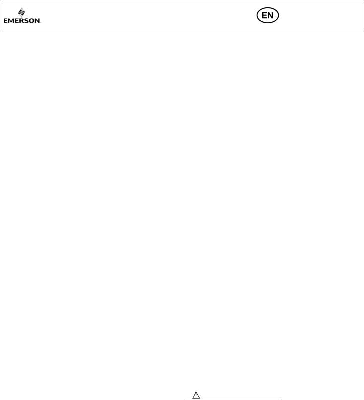
D i me n s i o n s ( m m ) :
 S a f e ty i n s tr u c t i o n s :
•Read operating instructions thoroughly. Failure to comply can result in device failure, system damage or personal injury.
•It is intended for use by persons having the appropriate knowledge and skill.
•Before installation or service disconnect all voltages from system and device.
•Do not operate system before all cable connections are completed.
•Do not apply voltage to the controller before completion of wiring.
•Entire electrical connections have to comply with local regulations.
•Inputs are not isolated, potential free contacts needed to be used.
.
•Disposal: Electrical and electronic waste must NOT be disposed of with other commercial waste. Instead, it is the user responsibility to pass it to a designated collection point for the safe recycling of Waste Electrical and Electronic Equipment (WEEE directive 2012/19/EU). For further information, contact your local environmental recycling center.
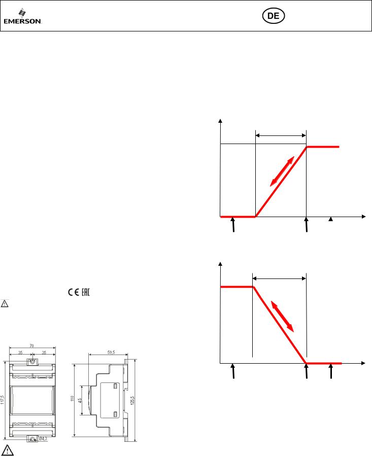
T e mp e r a t u r e s e t t i ng i n n o r ma l s e n s e
(Controller function as temperature controller)
Valve opening %
1tbd
100%
Temperature
0% |
|
|
1tAL |
1tst |
1tAH |
T e mp e r a t u r e s e t t i ng i n r e v e r s e se n s e
(Controller function as temperature controller)
Valve opening %
1tbd
100%
Temperature
0% |
|
|
|
|
|
|
|
|
|
|
|
|
|
|
|
1tAL |
1tst/ |
1tAH |
|
E l e c t r i c a l c o n ne c t i o n a n d w i r i ng : |
|
|
|
|
•Refer to the electrical wiring diagram for electrical connections.
•Note: Keep controller and sensor wiring well separated from supply power cables. Minimum recommended distance 30 mm.
•When connecting the wires of the EXV-M… (electrical plug of valves) consider the color coding as follows:
EXV-M…: WH: White; BK: Black; BN: Brown; BL: Blue
•The digital input DI1 (EXD-SH1/SH2) and DI2 (EXD-SH2) are the interfaces between EXD-SH1/2 and upper level system controller if the Modbus communication has not been used. The external digital inputs must be free of potential (dry contact) and shall be operated in function system’s compressor/demand.
Operating condition |
Digital input status |
Compressor starts/run |
External contact to be closed (Start) |
Compressor stops |
External contact to be open (Stop) |
Note: Connecting any EXD-SH1/2 inputs to the supply voltage will permanently damage the EXD-SH1/2
Emerson Climate Technologies GmbH |
www.climate.emerson.com/en-gb |
Date: 29.07.2020 |
Am Borsigturm 31 I 13507 Berlin I Germany |
|
EXD-SH12_OI_EN_DE_FR_IT_PL_RU_0720_R04_865917.docx |

Operating instructions
EXD-SH1/2 Controller with ModBus communication capability for electrical control valves
Wiring options: UPS (ECP-024) /Supercap (EXD-PM)
UPS for up to two controllers
24 V
One supercap for one EXD-SH1
24VAC/
VDC
See parameter 2uP * |
24 V |
24 V |
|
Two supercaps for one EXD-SH2
|
|
|
|
|
|
|
|
|
|
|
|
24 V |
|
|
|
|
|
|
|
|
|
24 V |
|||||
|
|
|
|
|
|
|
|
|
|
|
|
|
|
|
|
|
|
|
Warning: |
|
|
|
|||||
|
|
|
|
• |
Use a class II category transformer for 24VAC power supply. Do not ground |
||||||||
|
|
|
|
|
the 24VAC lines. We recommend using individual transformers for EXD- |
||||||||
|
|
|
|
|
SH1/2 controller and for third party controllers to avoid possible interference |
||||||||
|
|
|
|
|
or grounding problems in the power supply. |
||||||||
|
|
|
|
• |
If EXD-PM is connected, it is mandatory to have individual transformer for |
||||||||
|
|
|
|
|
EXD-SH… and EXD-PM. |
|
|
|
|||||
|
|
|
|
|
|
|
*) Parameter 2uP with No. 8 = only pressure |
||||||
|
Circuit 1 (EXD-SH1/SH2) |
|
14-17 |
Electrical control valve circuit 1 (ECV1) |
|||||||||
|
|
|
EXV-M… Electrical plug: wire colors |
sensor circuit 1 is used |
|||||||||
|
Circuit 2 (EXD-SH2) |
|
|
WH-white BK-black BL-blue BN-brown |
|
|
|
||||||
|
Download/upload key |
|
19-22 |
Electrical control valve circuit 2 (ECV2) |
|
|
|
||||||
|
|
|
EXV-M… Electrical plug: wire colors |
|
|
|
|||||||
1 and 7 |
Supply voltage 24 VAC/DC |
|
|
|
|
||||||||
|
|
WH-white BK-black BL-blue BN-brown |
|
|
|
||||||||
2 and 8 |
Temperature sensor circuit 1 |
|
23 and 24 |
RS485 (+/-terminal) |
|
|
|
|
|
|
|
|
|
3 and 8 |
Temperature sensor circuit 2 |
|
25 and 26 |
Alarm relay circuit 1 (C, NO) |
– |
Suitable for |
|
|
|
||||
|
|
|
|
24 VAC/DC |
|
|
|
|
|
|
|
|
|
4 and 5 |
PT5N… circuit 1 & circuit 2 (white wire: 4 – 20 mA |
|
27 and 28 |
Alarm relay circuit 2 (C, NO) – |
Suitable for |
|
|
|
|||||
|
signal) |
|
|
24 VAC/DC |
|
|
|
|
|
|
|
|
|
9 |
+ 12VDC Voltage input for PT5N… (brown wire) |
|
29 and 30 |
Digital input circuit1 (DI1) |
– |
Dry contact, |
|
|
|
||||
|
|
|
|
potential free |
|
|
|
|
|
|
|
|
|
Alternative ratiometric third Party Pressure Transmitter: |
|
Digital input circuit 2 (DI2) |
– |
Dry contact, |
|
|
|
||||||
Warning: Read the note in the last page for limitation of |
|
31 and 30 |
|
|
|
||||||||
|
potential free |
|
|
|
|
|
|
|
|
|
|||
error condition |
|
|
|
|
|
|
|
|
|
|
|
|
|
4 and 5 |
Pressure transmitter circuit 1 & circuit 2 |
|
35 and36 |
Battery/Super capacitor connection terminal |
|
|
|
||||||
|
(0.5 - 4.5 V signal) |
|
|
|
|
|
|
|
|
|
|
|
|
11 |
+ 5 VDC voltage input |
|
|
Fuse: EXD-SH1 (1A), EXD-SH2 (2A) |
|
|
|
||||||
10 |
GND Ground |
|
6,12,13, |
Not used (Terminals on EXD-SH12) |
|
|
|
||||||
|
18,32-34 |
|
|
|
|||||||||
|
|
|
|
|
|
|
|
|
|
|
|
|
|
Emerson Climate Technologies GmbH |
www.climate.emerson.com/en-gb |
|
|
|
|
|
Date: 29.07.2020 |
||||||
Am Borsigturm 31 I 13507 Berlin I Germany |
|
|
|
|
EXD-SH12_OI_EN_DE_FR_IT_PL_RU_0720_R04_865917.docx |
||||||||

Operating instructions
EXD-SH1/2 Controller with ModBus communication capability for electrical control valves
P r e pa r a t i o n f o r S ta r t - u p :
•Vacuum the entire refrigeration circuit.
•Note: EX/CV valves are delivered partially open position. Do not charge system with refrigerant before closure of valve.
•Apply supply voltage 24V to EXD-SH1/2 while the digital input (DI1/DI2) is open. The valve will be driven to close position.
•After closure of valve, start to charge the system with refrigerant.
S e t u p o f pa r a me t e r s :
(need to be checked/modified before system start-up)
•Make sure that digital input (DI1/DI2) is open. Turn on the 24V power supply to EXD-SH1/2.
•Parameters Password (H5), type of function (1Fct), refrigerant type (1u0/2u0), pressure sensor type (1uP/2uP) and valve scaling (1uF/2uF) need to be set according system requirement and only when digital input DI1/DI2 is open. This feature is for added safety to prevent accidental damage of compressors and other system components.
•Once the main parameters have been selected and saved, the EXD-SH1/2 is ready for startup. All other parameters can be modified at any time during operation or in system standby, if it is necessary.
D i s p l a y / ke y p a d u n i t : ( L E D s a n d b u t t o n f u nc t i o n s )
|
|
|
|
|
|
|
|
|
|
|
|
Observing operating |
|
|
|
|
|
|
|
Observing operating |
|
Circuit 1 is ON |
|
|
|
|
|
||||||||||
|
|
|
|
parameters of |
|
|
|
|
|
|||||||||
|
parameters of |
|
|
|
|
|
|
|
|
ON: alarm |
||||||||
|
|
|
|
|
|
|
|
circuit2 |
|
|||||||||
|
circuit1 |
|
|
|
Circuit 2 is ON |
|
|
OFF: no alarm |
||||||||||
|
|
|
|
|
|
|
|
|||||||||||
|
|
|
|
|
|
|
|
|
|
|
|
|
|
|
|
|
|
|
|
|
|
|
|
|
|
|
|
|
|
|
|
|
|
|
|
|
|
|
|
|
|
|
|
|
|
|
|
|
|
|
|
|
|
|
|
|
|
|
|
|
|
|
|
|
|
|
|
|
|
|
|
|
|
|
|
|
|
|
|
|
|
|
|
|
|
|
|
|
|
|
|
|
Upper |
|
|
|
|
|
|
|
|
|
|
|
|
|
|
|
|
|
|
Display |
|
|
|
|
|
|
|
|
|
|
|
|
|
|
|
|
|
|
|
|
|
|
|
|
|
|
|
|
|
|
|
|
|
|
Lower |
||||
|
Corresponding |
|
|
|
|
|
|
|
|
|
|
|
|
|
||||
|
valve of circuit |
|
|
|
|
|
|
|
|
|
|
|
|
|
Display |
|||
|
1 and or 2 is in |
|
|
|
|
|
|
|
|
|
|
|
|
|
|
|
||
|
regulation |
|
|
|
|
|
|
|
|
|
|
|
|
Data Display |
||||
|
|
|
|
|
|
|
|
|
|
|
|
|
|
|
|
Change 1/2 |
||
|
|
|
|
|
|
|
|
|
|
|
|
|
|
|
|
|||
|
|
|
|
|
|
|
|
|
|
|
|
|
|
|
|
|
|
|
|
Blinking: |
|
|
|
|
|
|
|
|
|
|
|
|
|
|
|
||
|
|
|
|
|
|
|
|
|
|
|
|
|
|
|||||
|
Valve is opening |
|
|
|
|
|
|
|
|
|
|
|
|
|
||||
|
|
|
|
|
|
|
|
|
|
|
|
|
|
|
|
Parameters |
||
|
|
|
|
|
|
|
|
|
|
|
|
|
|
|
|
|||
|
|
|
|
|
|
|
|
|
|
|
|
|
|
|
|
setting/saving |
||
|
Blinking: |
|
|
|
|
|
|
|
|
|
|
|
|
|
||||
|
|
|
|
|
|
|
Next parameter/ |
Next parameter/ |
|
|
|
|
||||||
|
valve is closing |
|
|
|
|
|
|
|
||||||||||
|
|
|
|
|
|
|
|
|
value (higher) |
value (lower) |
|
|
|
|
||||
|
|
|
|
|
|
|
|
|
|
|
|
|||||||
|
|
|
|
|
|
|
|
|
|
|
||||||||
|
|
|
|
|
|
|
|
|
||||||||||
|
Activating/deactivating |
|
Manual Instant values |
|
|
|
|
|
|
|||||||||
|
instant values display mode |
|
display mode active |
|
|
|
|
|
|
|||||||||
|
|
|
|
|
|
|
|
|
|
|
|
|
|
|
|
|
|
|
D i s p l a y de s c r i p t i o n :
|
|
Selected main function |
|
||
|
Superheat control |
|
Temperature |
||
|
Compressor |
|
Compressor |
|
control |
|
ON |
|
OFF |
|
|
|
|
|
|
||
Upper display |
Superheat (K/F) |
|
Superheat (K/F) |
|
Controlled |
|
|
temperature |
|||
shows |
|
|
|||
|
|
|
|
(°C/F) |
|
|
|
|
|
|
|
Lower display |
Valve opening |
|
Suction pressure |
|
Valve opening |
shows |
(%) |
|
(bar/psig) |
|
(%) |
Note: when Superheat value is blinking, the controller is in MOP function.
I n s t a n t v a l ue d i s pl a y mo d e :
• The controller displays the values of one circuit at a time, to change from one
circuit to the other, press |
button (Function only for EXD-SH2). |
• By pressing the |
key, the instant value display mode can be |
activated/deactivated, which allows the user to check the measured/calculated values in real time in a sequence shown as below table:
Value on upper display |
Code on lower display |
Superheat (K/F) |
SH |
Valve opening (%) |
OPEn |
Suction temperature (°C/°F) |
tASP |
Suction pressure (bar/psig) |
PEuA |
Saturation temperature (°C/°F) |
tEuA |
Software version: (0A) |
SH1 or SH2 |
Repeating display of values
P a r a me t e r c o nf i g u r a t i o n mo d e :
The configuration of parameters is protected by a numerical password. The default password is “12”. To enter the parameter configuration:
•Press both the  and
and  buttons for more than 5 seconds.
•A flashing “0” is displayed in upper and “PAS” at lower.
•Press  until “12” is displayed; (password).
•Press  to confirm password.
•Press  or
or  to show the code of the parameter (see table of parameter codes) that has to be accessed/changed.
•Press  to choose and adjust parameter value.
•Press  or
or  to increase or decrease the value.
•Press  to temporarily confirm the new value. The selected value blinks a few times and the display shows the next available parameter code.
•Repeat the procedure for other parameters if needed.
To exit and save the new settings:
•When all parameters where changed press  to save all the new values and exit the parameters modification procedure.
To exit and not save the new settings:
•Press  and
and  to cancel the parameter modification and delete any changes made.
•Another way to exit without saving the changes made at the parameters is to not press any button for at least 120 seconds (TIME OUT).
•Note: While in parameter modification mode, the controller will display the parameter code on the lower display and the parameter value on the upper display.
Special manual functions: (Rest, clear)
•Press both the  and
and  buttons for more than 5 seconds.
•A flashing “0” is displayed.
•Press  until “12” is displayed; (if default password has been changed, it must select the new password)
•Press  to confirm password
•Select the special function as explained at the parameter configuration mode
The special functions are:
Displayed Value |
Code |
Factory Reset |
-Fdt |
Clear Alarms (only manual reset) |
ALrr |
•The default value for each variable is 0, when it set to 1 it will trigger the corresponding function.
•The factory reset of the controller (-Fdt) is possible when digital input DI1/DI2 is open.
M a n u a l Va l v e o p e r a t i o n ( se r v i c e / ma i n t e n a n c e ) :
• Press  for more than 5 seconds
Select, modify and save the variables like explained at the parameter configuration mode
Code |
Parameter description and choices |
Min |
Max |
Factory |
Field |
||
|
|
|
|
|
|
setting |
setting |
1Ho |
Manual mode operation; circuit 1 |
0 |
1 |
|
0 |
|
|
0 = disabled |
1 = Enabled |
|
|
|
|
|
|
|
|
|
|
|
|
||
1HP |
Valve opening (%) |
0 |
100 |
|
0 |
|
|
2Ho |
Manual mode operation; circuit 2 |
0 |
1 |
|
0 |
|
|
0 = disabled |
1 = Enabled |
|
|
|
|
|
|
|
|
|
|
|
|
||
2HP |
Valve opening (%) |
0 |
100 |
|
0 |
|
|
Note: During manual operation, functional alarms such as low superheat are disabled. It is recommended to monitor the system operation when the controller is operated manually. Manual operation is intended for service or temporary operation of valve at a specific condition. After achieving the required operation, set the parameter 1Ho and 2Ho at 0 so the controller automatically operates the valve(s) according to its setpoint(s).
Emerson Climate Technologies GmbH |
www.climate.emerson.com/en-gb |
Date: 29.07.2020 |
Am Borsigturm 31 I 13507 Berlin I Germany |
|
EXD-SH12_OI_EN_DE_FR_IT_PL_RU_0720_R04_865917.docx |
Operating instructions
EXD-SH1/2 Controller with ModBus communication capability for electrical control valves
L i s t o f pa r a me t e r s i n sc r o l l i ng s e q ue n c e b y p r e s si n g  b u t t o n :
|
Code |
|
Parameter description and choices |
|
|
Min |
|
Max |
|
|
Factory |
|||
|
|
|
|
|
|
|
setting |
|||||||
|
|
|
|
|
|
|
|
|
|
|
|
|
|
|
|
H5 |
|
Password |
|
|
|
|
|
1 |
1999 |
|
12 |
||
|
Adr |
|
ModBus address |
|
|
|
|
|
1 |
|
127 |
|
1 |
|
|
br |
|
Modbus baudrate |
|
|
|
|
|
0 |
|
1 |
|
0 |
|
|
PAr |
|
Modbus parity |
|
|
|
|
|
0 |
|
1 |
|
0 |
|
|
-C2 |
|
Circuit 2 of EXD-SH2 enabled |
|
|
|
0 |
|
1 |
|
1 |
|||
|
|
0 =Disabled |
|
|
1 = Enabled |
|
|
|
|
|
|
|||
|
|
|
|
|
|
|
|
|
|
|
||||
|
-uC |
|
Units conversion |
|
|
|
|
|
0 |
|
1 |
|
0 |
|
|
|
0 = °C, K, bar |
|
|
1 = F, psig |
|
|
|
|
|
|
|||
|
|
|
|
|
|
|
|
|
|
|
||||
|
Circuit |
1 Parameters |
|
|
|
|
|
|
|
|
|
|
|
|
|
1Fct |
|
Function |
|
|
|
|
|
0 |
|
2 |
|
0 |
|
|
|
0 = Superheat control |
1 = Temperature |
control |
|
normal sense |
||||||||
|
|
|
2 = temperature control reverse sense |
|
|
|
|
|
|
|
|
|
||
|
1u4 |
|
Control Mode |
|
|
|
|
|
0 |
|
3 |
|
0 |
|
|
|
0 = standard |
|
|
1 = slow |
|
|
|
|
|
|
|
|
|
|
|
|
2 = intermediate control |
|
3 = adjustable fixed PID |
|
|
|
||||||
|
|
|
Refrigerant type |
|
|
|
|
|
0 |
|
19 |
|
1 |
|
|
|
|
0 = R22 |
1 = R134a |
2 = R507 |
|
|
|
3 = R404A |
|
|
|||
|
1u0 |
|
4 = R407C |
5 = R410A |
6 = R124 |
|
|
7 = R744 |
||||||
|
|
8 = R407A |
9 = R407F |
10 = R23 |
|
|
|
11 = R32* |
||||||
|
|
|
|
|
|
|||||||||
|
|
|
12 = R1234ze* |
13 = R448A |
14 = R449A |
|
15 = R450A |
|||||||
|
|
|
16 = R513A |
17 = R290* |
18 = R1270* |
|
19 = R454C* |
|||||||
|
|
|
Pressure sensor type |
|
|
|
|
0 |
|
8 |
|
1 |
||
|
1uP |
|
0 = PT5N-07x |
1 = PT5N-18x |
2 = PT5N-30x |
|
|
|
||||||
|
|
3 = PT5N-50x |
4 = PT5N-150D |
5 = PT5N-10P-FLR |
||||||||||
|
|
|
||||||||||||
|
|
|
6 = Ratio metric (gauge) |
7 = Ratio metric (absolute) |
8 = Modbus |
|||||||||
|
1Prr |
|
Ratio metric range (bar) |
|
|
|
|
3 |
|
60 |
|
30 |
||
|
|
|
Valve type |
|
|
|
|
|
0 |
|
12 |
|
0 |
|
|
1ut |
|
0 = EX4-6(FLR) |
1 = EX7(FLR) |
2 = EX8 |
|
3 = N/A |
4 |
= N/A |
|||||
|
|
5 = N/A |
6 = N/A |
7 = N/A |
8 = N/A |
9 = N/A |
||||||||
|
|
|
||||||||||||
|
|
|
10 = CV4 |
11 = CV5-6 |
12 = CV7 |
|
|
|
|
|
|
|||
|
1uF |
|
Valve scaling (%) |
|
|
|
|
|
5 |
|
100 |
|
100 |
|
|
1uu |
|
Start opening (%) |
|
|
|
|
|
0 |
|
100 |
|
10 |
|
|
1u9 |
|
Start opening duration (s) |
|
|
|
|
0 |
|
120 |
|
5 |
||
|
1uL |
|
Low superheat alarm |
|
|
|
|
0 |
|
2 |
|
1 |
||
|
|
0 = disabled |
1 = enabled auto reset |
|
|
|
|
|
||||||
|
|
2 = enabled manual reset |
||||||||||||
|
|
|
Alarm at 0.5K (if it maintains 1 min.); Alarm clear immediately at 3K |
|||||||||||
|
1u5 |
|
Superheat set point (K) |
|
|
|
|
0.5 |
|
30 |
|
6 |
||
|
|
Range = 3-30 K if parameter 1uL is set to 1 or 2 |
|
|
|
|
|
|
|
|
||||
|
|
|
|
|
|
|
|
|
|
|
||||
|
1u2 |
|
MOP function |
|
|
|
|
|
0 |
|
1 |
|
1 |
|
|
|
0 = disabled |
|
|
1 = Enabled |
|
|
|
|
|
|
|||
|
|
|
|
|
|
|
|
|
|
|
||||
|
|
|
MOP saturation temp (°C) |
|
|
|
|
|
|
|
|
|
(see |
|
|
1u3 |
|
Factory setting according to selected refrigerant |
|
- |
|
- |
|
|
MOP |
||||
|
|
|
(1u0). The default value can be changed |
|
|
|
|
|
|
|
table) |
|||
|
1P9 |
|
Low pressure alarm mode |
|
|
|
|
0 |
|
2 |
|
0 |
||
|
|
0 = disabled |
1 = enabled auto-reset |
2 = enabled manual reset |
||||||||||
|
|
|||||||||||||
|
|
|
||||||||||||
|
1PA |
|
Low pressure alarm cut-out (bar) |
|
|
|
-0.8 |
|
17.7 |
|
0 |
|||
|
1Pb |
|
Low pressure alarm delay (s) |
|
|
|
5 |
|
199 |
|
5 |
|||
|
1Pd |
|
Low pressure alarm cut-in (bar) |
|
|
|
-0.5 |
|
18 |
|
0.3 |
|||
|
1P4 |
|
Freeze alarm delay mode |
|
|
|
|
0 |
|
2 |
|
0 |
||
|
|
0 = disabled |
1 = enabled auto-reset |
2 = enabled manual reset |
||||||||||
|
|
|||||||||||||
|
|
|
||||||||||||
|
1P2 |
|
Freeze alarm cut-out (°C) |
|
|
|
|
-5 |
|
5 |
|
0 |
||
|
1P5 |
|
Freeze alarm delay (s) |
|
|
|
|
5 |
|
199 |
|
|
30 |
|
|
1P- |
|
Superheat control circuit1 (Kp factor) |
|
|
|
0.1 |
|
10 |
|
|
1.0 |
||
|
|
|
Display 1/10K |
|
|
|
|
|
|
|
|
|
|
|
|
1i- |
|
Superheat control circuit1 (Ti factor) |
|
|
|
1 |
|
350 |
|
100 |
|||
|
1d- |
|
Superheat control circuit1 (Td factor) |
|
|
|
0.1 |
|
30 |
|
|
3.0 |
||
|
|
|
Display 1/10K |
|
|
|
|
|
|
|
|
|
|
|
|
1uH |
|
High superheat alarm mode |
|
|
|
|
0 |
|
1 |
|
0 |
||
|
|
0 = disabled |
|
|
1 = enabled auto-reset; |
|
|
|
||||||
|
|
|
|
|
|
|
|
|||||||
|
1uA |
|
High superheat alarm set point (K) |
|
|
|
16 |
|
40 |
|
30 |
|||
|
1ud |
|
High superheat alarm delay (min) |
|
|
|
1 |
|
15 |
|
3 |
|||
|
1tSt |
|
Temperature control set point (°C) |
|
|
|
-80 |
|
50 |
|
4 |
|||
|
1tbd |
|
Temperature band (K) |
|
|
|
|
1 |
|
10 |
|
|
2 |
|
|
1tAF |
|
Temperature alarm mode |
|
|
|
|
0 |
|
1 |
|
0 |
||
|
|
0 = disabled |
|
1 = enabled |
|
|
|
|
|
|
|
|
||
|
|
|
|
|
|
|
|
|
|
|
|
|||
|
1tAL |
|
Min. temperature alarm set point (°C) |
|
|
|
-50 |
|
50 |
|
0 |
|||
|
1tdL |
|
Min. temperature alarm delay (min) |
|
|
|
1 |
|
10 |
|
3 |
|||
|
1tAH |
|
Max. temperature alarm set point (°C) |
|
|
-50 |
|
50 |
|
15 |
||||
|
1tdH |
|
Max. temperature alarm delay (min) |
|
|
|
1 |
|
10 |
|
3 |
|||
|
1tt |
|
Temperature sensor type |
|
|
|
|
0 |
|
1 |
|
0 |
||
|
|
0 = ECN-Nxx (-45…+40°C) / TP1-…(-45…+150°C) |
|
|
|
|
|
|
|
|||||
|
|
|
1 = ECN-Z... ( -80…-40°C) for R23 |
|
|
|
|
|
|
|
|
|
||
|
Code |
|
Parameter description and choices |
|
|
Min |
|
Max |
|
|
Factory |
|||
|
|
|
|
|
|
|
setting |
|||||||
|
|
|
|
|
|
|
|
|
|
|
|
|
|
|
Circuit |
2 Parameters (only EXD-SH2) |
|
|
|
|
|
|
|
|
|
|
|||
|
2u4 |
|
Control Mode |
|
|
|
|
|
0 |
3 |
|
0 |
||
|
|
0 = standard |
|
|
1 = slow |
|
|
|
|
|
|
|
|
|
|
|
|
2 = intermediate control |
|
3 = adjustable fixed PID |
|
|
|
||||||
|
|
|
Refrigerant type |
|
|
|
|
|
0 |
19 |
|
1 |
||
|
|
|
0 = R22 |
1 = R134a |
|
2 = R507 |
|
|
3 = R404A |
|
|
|||
|
2u0 |
|
4 = R407C |
5 = R410A |
|
6 = R124 |
|
7 = R744 |
||||||
|
|
8 = R407A |
9 = R407F |
|
10 = R23 |
|
|
|
11 = R32* |
|||||
|
|
|
|
|
|
|
||||||||
|
|
|
12 = R1234ze* |
13 = R448A |
|
14 = R449A |
|
15 = R450A |
||||||
|
|
|
16 = R513A |
17 = R290* |
|
18 = R1270* |
|
19 = R454C* |
||||||
|
|
|
Pressure sensor type |
|
|
|
|
0 |
9 |
|
1 |
|||
|
2uP |
|
0 = PT5N-07x |
1 = PT5N-18x |
2 = PT5N-30x |
|
|
|
||||||
|
|
3 = PT5N-50x |
4 = PT5N-150D |
5 = PT5N-10-FLR |
|
|
|
|||||||
|
|
6 = Ratio metric (gauge) |
|
|
7 = Ratio metric (absolute) |
|||||||||
|
|
|
8 = Modbus |
9 = Pressure sensor circuit1 is used (1uP) |
|
|
|
|||||||
|
2Prr |
|
Ratio metric range (bar) |
|
|
|
|
3 |
|
60 |
|
|
30 |
|
|
|
|
Valve type |
|
|
|
|
|
0 |
12 |
|
0 |
||
|
2ut |
|
0 = EX4-6(FLR) |
1 = EX7(FLR) |
2 = EX8 |
|
3 = N/A |
4 |
= N/A |
|||||
|
|
5 = N/A |
6 = N/A |
|
7 = N/A |
8 = N/A |
9 = N/A |
|||||||
|
|
|
|
|||||||||||
|
|
|
10 = CV4 |
11 = CV5-6 |
|
12 = CV7 |
|
|
|
|
|
|
||
|
2uF |
|
Valve scaling (%) |
|
|
|
|
|
5 |
100 |
|
100 |
||
|
2uu |
|
Start opening (%) |
|
|
|
|
|
0 |
100 |
|
10 |
||
|
2u9 |
|
Start opening duration (s) |
|
|
|
|
0 |
120 |
|
5 |
|||
|
2uL |
|
Low superheat alarm |
|
|
|
|
0 |
2 |
|
1 |
|||
|
|
0 = disabled |
1 = enabled auto reset |
2 = enabled |
manual |
reset |
||||||||
|
|
|
Alarm at 0.5K (if it maintains 1 min.); Alarm clear immediately at 3K |
|||||||||||
|
2u5 |
|
Superheat set point (K) |
|
|
|
|
0.5 |
30 |
|
6 |
|||
|
|
Range = 3-30K if parameter 2uL is set to 1 or 2 |
|
|
|
|
|
|
|
|
||||
|
|
|
|
|
|
|
|
|
|
|
||||
|
2u2 |
|
MOP function |
|
|
|
|
|
0 |
1 |
|
1 |
||
|
|
0 = disabled |
|
|
1 = Enabled |
|
|
|
|
|
|
|||
|
|
|
|
|
|
|
|
|
|
|
||||
|
|
|
MOP saturation temp (°C) |
|
|
|
|
|
|
|
|
|
(see |
|
|
2u3 |
|
Factory setting according to selected refrigerant |
|
- |
|
- |
|
|
MOP |
||||
|
|
|
(2u0). The default value can be changed |
|
|
|
|
|
|
|
table) |
|||
|
2P9 |
|
Low pressure alarm mode |
|
|
|
|
0 |
2 |
|
0 |
|||
|
|
0 = disabled |
1 = enabled auto-reset |
2 = enabled manual reset |
||||||||||
|
|
|
||||||||||||
|
2PA |
|
Low pressure alarm cut-out (bar) |
|
|
|
|
-0.8 |
17.7 |
|
0 |
|||
|
2Pb |
|
Low pressure alarm delay (s) |
|
|
|
|
5 |
199 |
|
5 |
|||
|
2Pd |
|
Low pressure alarm cut-in (bar) |
|
|
|
|
-0.5 |
18 |
|
0.3 |
|||
|
2P4 |
|
Freeze alarm delay mode |
|
|
|
|
0 |
2 |
|
0 |
|||
|
|
0 = disabled |
1 = enabled auto-reset |
2 = enabled manual reset |
||||||||||
|
|
|
||||||||||||
|
2P2 |
|
Freeze alarm cut-out (°C) |
|
|
|
|
-5 |
5 |
|
0 |
|||
|
2P5 |
|
Freeze alarm delay (s) |
|
|
|
|
5 |
|
199 |
|
|
30 |
|
|
2P- |
|
Superheat control circuit2 |
|
|
|
|
0.1 |
10 |
|
1.0 |
|||
|
|
|
(Kp factor), fixed PID |
Display 1/10K |
|
|
|
|
|
|
|
|||
|
2i- |
|
Superheat control circuit2 (Ti factor), |
|
|
|
1 |
|
350 |
|
|
100 |
||
|
|
|
fixed PID |
|
|
|
|
|
|
|
|
|
|
|
|
2d- |
|
Superheat control circuit2 |
|
|
|
|
0.1 |
30 |
|
3.0 |
|||
|
|
|
(Td factor), fixed PID |
Display 1/10K |
|
|
|
|
|
|
|
|||
|
2uH |
|
High superheat alarm mode |
|
|
|
|
0 |
1 |
|
0 |
|||
|
|
0 = disabled |
|
|
1 = enabled auto-reset; |
|
|
|
||||||
|
|
|
|
|
|
|
|
|||||||
|
2uA |
|
High superheat alarm set point (K) |
|
|
|
16 |
40 |
|
30 |
||||
|
2ud |
|
High superheat alarm delay (min) |
|
|
|
1 |
15 |
|
3 |
||||
|
2tt |
|
Temperature sensor type |
|
|
|
|
0 |
1 |
|
0 |
|||
|
|
0 = ECN-Nxx (-45…+40°C) / TP1-…(-45…+150°C) |
|
|
|
|
|
|
|
|||||
|
|
|
1 = ECN-Z60 ( -80°C…-40°C) for R23 |
|
|
|
|
|
|
|
|
|
||
*) |
Warning -Flammable refrigerants: |
|
|
|
|
|
|
|
|
|
||||
EXD-SH1/2 (EXD-PM, ECP-024) has a potential ignition source and does not comply with ATEX requirements. Installation only in non-explosive environment. For flammable refrigerants only use valves and accessories approved for it!
MOP default value table:
Refrigerant |
Default (C°) |
Refrigerant |
Default (C°) |
Refrigerant |
Default (C°) |
R22 |
+13 |
R744 |
-5 |
R449A |
+12 |
R134a |
+15 |
R407A |
+10 |
R450A |
+19 |
R507 |
+7 |
R407F |
+10 |
R513A |
+13 |
R404A |
+7 |
R23 |
-40 |
R290 |
+15 |
R407C |
+15 |
R32 |
+15 |
R1270 |
+15 |
R410A |
+15 |
R1234ze |
+24 |
R454C |
+17 |
R124 |
+50 |
R448A |
+12 |
|
|
Emerson Climate Technologies GmbH |
www.climate.emerson.com/en-gb |
Date: 29.07.2020 |
Am Borsigturm 31 I 13507 Berlin I Germany |
|
EXD-SH12_OI_EN_DE_FR_IT_PL_RU_0720_R04_865917.docx |

Operating instructions
EXD-SH1/2 Controller with ModBus communication capability for electrical control valves
C o n t r o l ( v a l v e ) s t a r t - u p be h a v i o r f a c to r y se t t i n g s
(1uu + 1u9) / (2uu +2u9)
EX4/5/6 ≤ 5.3 Seconds
EX7 ≤ 5.6 Seconds
EX8 ≤ 5.9 Seconds
CV4 ≤ 5.3 Seconds
CV5/6 ≤ 5.3 Seconds
CV7 ≤ 6.6 Seconds
U p l o a d / do w nl o a d K e y : F un c t i o n
For serial production of systems/units, upload/download key allows the transmission of configured parameters among range of identical systems.
Uploading procedure (storing configured parameters in key):
•Insert the key while the first (reference) controller is ON and press  button; the “uPL” message appears followed by “End” message for 5 seconds.
•Note: If the “Err” message is displayed for failed programming, repeat the
E r r o r / A l a r m h a n d l i ng :
above procedure.
Downloading procedure (configured parameters from key to other controllers):
•Turn off power to new controller.
•Insert a loaded Key (with stored data from reference controller) into new controller and turn on the power supply.
•The stored parameters of the key will be downloaded automatically into the new controller memory; The “doL” message appears followed by a “End” message for 5 seconds.
•The new controller with new loaded parameters setting will start to operate after “End” message disappears.
•Remove the key.
•Note: If the “Err” message is displayed for failed programming, repeat the above procedure.
Alarm |
Description |
Related |
Alarm |
Valve |
|
Requires clear |
|
What to do? |
alarm after |
||||||
code |
parameter |
relay |
|||||
|
|
resolving alarm |
|||||
|
|
|
|
|
|
||
1E0/2E0 |
Pressure sensor circuit 1/2 error |
- |
Triggered |
Fully close |
Check wiring connection and measure the signal. |
No |
|
1E1/2E1 |
errorTemperature sensor circuit 1/2 |
- |
Triggered |
Fully close |
Check wiring connection and measure the resistance of sensor. |
No |
|
1Π/2Π |
Valve Circuit 1/2 electrical |
- |
Triggered |
- |
Check wiring connection and measure the resistance of winding. |
No |
|
connection error |
|||||||
AFE 1/2 |
Freeze protection circuit 1/2 |
1P4/2P4:1 |
Triggered |
Fully close |
Check the system for cause of low pressure such as insufficient load on |
No if it is ON |
|
AFE 1/2 |
1P4/2P4:2 |
Triggered |
Fully close |
Yes if it is blinking |
|||
|
evaporator. |
||||||
LSH 1/2 |
Low superheat |
1uL/2uL:1 |
Triggered |
Fully close |
Check wiring connection and operation of valve. |
No if it is ON |
|
LSH 1/2 |
1uL/2uL:2 |
Triggered |
Fully close |
Yes if it is blinking |
|||
(<0,5K) |
|
||||||
tAL1 |
Min. temperature alarm |
1tAL |
Triggered |
Fully close |
Check wiring connection, operation of valve, size of valve and load. |
No |
|
tAH1 |
Max. temperature alarm |
1tAH |
Triggered |
Fully close |
No |
||
HSH 1/2 |
High superheat circuit 1/2 |
1uH/2uH:1 |
Triggered |
Operating |
Check the system. |
No |
|
LOP 1/2 |
Low pressure circuit 1/2 |
1P9/2P9 1 |
Triggered |
Operating |
Check the system for cause of low pressure such as refrigerant loss. |
No if it is ON |
|
LOP 1/2 |
1P9/2P9 2 |
Triggered |
Operating |
Yes if it is blinking |
|||
|
|
||||||
Err |
Failed |
- |
- |
- |
Repeat again the procedure for uploading/downloading. |
No |
|
uploading/downloading |
|||||||
|
|
|
|
|
|
||
ACEr |
|
|
|
|
Check Modbus communication. Note: Modbus alarm (ACEr) detection is |
|
|
Modbus Timed Out |
- |
- |
- |
active only when the pressure sensor type is configured to be Modbus type |
No |
||
|
|
|
|
|
and the corresponding circuit is on demand. |
|
|
PFA |
Power failure alarm |
- |
Triggered |
Fully close |
When the controller is connected to the battery supply and power supply |
No |
|
interrupted, this alarm code will be displayed while the valve is closing. |
ACF1 or ACF2: Alarm code (circuit1/2) for “not permitted configuration/ selection” Alarm will be displayed for the following cases:
•If two circuits of the EXD-SH2 are connected to two different type of pressure transducers i.e. 4-20 mA and 0-5 V. It is mandatory that two circuits always are connected to the same type of pressure transmitter technology.
•Temperature control function is possible only with EX4-8 series valves. If other valves are used, then the ACF alarm will be displayed.
•Ratiometric pressure transmitters cannot be selected in conjunction with R744.
Notes:
S e r v i c e / T r o u bl e s ho o ti n g :
•When several alarms are present, the alarms will be shown one after the other on the lower display.
•Pressure sensor error for third party ratiometric pressure transmitters is based on detection of interruption of two wires (5 V and signal 0.5 - 4.5 V). If only third wire (ground) is open/ interrupted, no error can be detected and controller will receive a false signal between 50% and 100% higher. This false signal leads to improper operation of EXD-SH1/2 controller and can lead to system/compressor damage. EMERSON is not responsible in such cases.
Symptom |
Cause |
Action |
Operating superheat is several degrees higher or |
Incorrect signal from pressure or temperature |
1- Check the sensors (see list of parameters) |
lower than set-point |
sensors |
2- Make sure the sensor cables are not installed along with other high voltage |
|
|
cables |
Operating superheat is too low i.e. compressor wet |
1- Incorrect wiring of ECVs |
1- Check the wiring |
running |
2- Defective sensors |
2- Check the sensor |
Valve is not fully closed |
1- The digital input is ON |
1- Valve is shut off only when the digital input is turned off. |
|
2- Wrong setting of parameter ut. |
2- Check the setting of parameter ut. |
Instable superheat (hunting) |
Evaporator is designed to operate at higher |
Increase the superheat set-point. |
|
superheat |
|
Valve opens when EXD commands to close and |
Wrong wiring between EXD-SH... and valve |
Correct the wiring. |
vice versa |
|
|
EX8 is not able to open at high differential |
Wrong setting of parameter ut |
Check the parameter ut. (Larger valve requires higher torque and higher |
pressure |
|
current) |
Superheat set-point is shifting after several months |
Stepper motor driven valves require |
Do not jumper digital input permanently. Interrupt digital input once every |
of uninterrupted operation or permanent jumper of |
synchronization |
week for 10 seconds if compressor never stops. |
24 V digital input |
|
|
Emerson Climate Technologies GmbH |
www.climate.emerson.com/en-gb |
Date: 29.07.2020 |
Am Borsigturm 31 I 13507 Berlin I Germany |
|
EXD-SH12_OI_EN_DE_FR_IT_PL_RU_0720_R04_865917.docx |
Betriebsanleitung
EXD-SH1/2 Regler mit ModBus Kommunikation für elektrische Regelventile
B e s c h r e i b u n g :
EXD-SH1/2 eigenständige Überhitzungsund Temperaturregler. Der EXD-SH1 ist für ein bipolares elektrisches Regelventil aus den Serien EX/CV, der EXD-SH2 für zwei getrennt arbeitende Ventile.
Folgende Anwendungen sind möglich:
Regler |
Regelkreis 1 |
Regelkreis 2 |
EXD-SH1 |
Überhitzungsoder Temperaturregelung |
|
EXD-SH2 |
Überhitzungsoder Temperaturregelung |
Überhitzungsregelung |
Hinweis:
Es ist möglich nur den Kreislauf 1 vom EXD-SH2 zu verwenden. In diesem Falle muss der Kreislauf 2 über den Parameter C2 abgeschaltet werden; Ventil und Sensoren brauchen nicht angeschlossen werden.
Die ModBus Kommunikation ist im Technical Bulletin beschrieben und nicht Teil dieses Dokuments.
T e c h ni s c h e D a te n :
Versorgungsspannung |
24VAC/DC +10%/-10% 50/60 Hz, |
||
Leistungsaufnahme |
EXD-SH1: 25 VA |
EXD-SH2: 50 VA |
|
Steckerverbindung |
Abnehmbare Schraubklemmen für Kabelquerschnitte |
||
von 0,14 bis 1,5 mm2 |
|
||
Schutzklasse |
IP00 |
|
|
|
ECN-N… / TP1… |
|
|
Temperaturfühler |
(Temperaturbereich bis |
-45°C) |
|
ECN-Z… (Temperaturbereich bis -80°C, |
|||
|
|||
|
Tieftemperatur) |
|
|
Zulässige |
|
|
|
Umgebungstemperatur bei |
0…+55°C |
|
|
Betrieb |
|
|
|
Maximale Kabellänge |
50 cm |
|
|
zwischen EXD-SH und |
|
||
AWG 18 adrig, Querschnitt (≥ 1 mm2) |
|||
EXD-PM |
|
|
|
Drucktransmitter |
PT5N, PT5N-FLR oder ratiometrische Sensoren |
||
Belastbarkeit Alarm-Relais |
Resistive Load 24 V AC/DC, 1 A |
||
Inductive Load 24 V AC/DC, 0,5 A |
|||
|
|||
Kontakt geschlossen: |
Während Alarm |
|
|
Kontakt offen: |
Während Normalbetrieb und AUS |
||
Versorgungsspannung |
|
||
|
|
||
Schrittmotorausgang |
Ventile: EX4-8 (EX4-7-FLR), CV4-7 |
||
Montage |
Standard Schienenmontage |
||
Kennzeichnung |
, |
|
|
|
|
||
|
|
|
|
Warnung:
EXD-SH1/2 (EXD-PM, ECP-024) hat eine potentielle Zündquelle und entspricht nicht den ATEX Bestimmungen. Installation nur in nicht explosionsgefährdeter Umgebung. Für brennbare Kältemittel nur Ventile und Zubehörteile, die dafür zugelassen sind verwenden!
A b me s s u n g e n ( m m ) :
S i c h e r h e i t s h i nw e i s e :
•Lesen Sie die Betriebsanleitung gründlich. Nichtbeachtung kann zum Versagen oder zur Zerstörung des Gerätes und zu Verletzungen führen.
•Der Einbau darf nur von Fachkräften vorgenommen werden.
•Der Kältekreislauf darf nur in drucklosem Zustand geöffnet werden.
•Die Anlage erst in Betrieb nehmen, wenn alle Kabelverbindungen vollständig sind.
•• Die Anlage darf erst dann in Betrieb genommen werden, wenn alle Verbindungen hergestellt sind.
•Für den gesamten elektrischen Anschluss sind die länderspezifischen Vorschriften einzuhalten.
•Digitaleingänge sind spannungsbehaftet; nur potentialfreie Schaltkontakte verwenden.
•Entsorgung: Elektround Elektronik-Altgeräte dürfen nicht mit anderen Gewerbemüll entsorgt werden. Stattdessen ist es in der Verantwortung Benutzer es zu einem Sammelpunkt für die sichere Entsorgung von Elektround ElektronikAltgeräte (WEEE-Richtlinie 2012/19/EU) zu übergeben. Für weitere Informationen kontaktieren Sie bitte Ihren örtlichen Recyclinghof.
T e mp e r a t u r e i n s t e l l u n g e n D i r e kt - P r o p o r t i o na l b e tr i e b
(Temperatur-Regelmodus)
Ventilöffnung %
1tbd
100%
Temperatur
0%
1tAL |
1tst |
|
|
1tAH |
|||
T e mp e r a t u r e i n s t e l l u n g e n In d i r e kt - P r o p o r t i o na l b e tr i e b
(Temperatur-Regelmodus)
Ventilöffnung %
1tbd
100%
Temperatur
0% |
|
|
1tAL |
1tst/ |
1tAH |
E l e kt r i s c h e r A n s c h l u s s u n d V e r d r a h t u n g :
•Den elektrischen Anschluss gemäß Verdrahtungsschema durchführen!
•Hinweis: Signalleitungen und Leitungen mit Netzspannung in getrennten Kabelschächten verlegen, Mindestabstand 30mm.
•Bei Anschluss von EXV-M… (Ventilstecker) muss die Farbe der Adern wie
folgt berücksichtigt werden:
EXV-M…: WH: Weiß; BK: Schwarz; BN: Braun; BL: Blau
•Die Digitaleingänge DI1 (EXD-SH1/SH2) und DI2 (EXD-SH2) sind die Schnittstellen zwischen EXD-SH1/2 und dem übergeordnetem Systemregler, wenn keine Modbus Kommunikation eingesetzt wird. Die externen Schaltkontakte müssen potentialfrei sein (dry contact) und entsprechend der Systemanforderung angesteuert werden.
Betriebszustand |
Status Digitaleingang |
Verdichter startet/läuft |
Externe Schaltkontakte schließen (Start) |
Kompressor stoppt |
Externe Schaltkontakte öffnen (Stopp) |
Hinweis: Das Aufschalten von externer Spannung auf die Digitaleingänge führt zur dauerhaften Beschädigung des EXD-SH1/2.
Emerson Climate Technologies GmbH |
www.climate.emerson.com/en-gb |
Date: 29.07.2020 |
Am Borsigturm 31 I 13507 Berlin I Germany |
|
EXD-SH12_OI_EN_DE_FR_IT_PL_RU_0720_R04_865917.docx |

Betriebsanleitung
EXD-SH1/2 Regler mit ModBus Kommunikation für elektrische Regelventile
EXV-M… |
EXV-M… |
Kabel & |
Kabel & |
Stecker |
Stecker |
EXD-M…
Kabel & Stecker
24VAC/
VDC
Temperaturfühler
ECN-N…/ Siehe Parameter 2uP
TP1-…/
ECN-Z…
Drucktransmitter PT5N-…
Möglichkeiten Verdrahtung: UPS (ECP-024) /Supercap (EXD-PM)
UPS für bis zu zwei Controller
Ein Supercap für ein EXD-SH1
Zwei Supercaps für ein EXD-SH2
Warnung:
•Für die 24V Stromversorgung sind ausschließlich Transformatoren der Klasse II zu verwenden. Die 24V Leitungen dürfen nicht geerdet werden. Wir empfehlen die Verwendung jeweils separater EMERSON Transformatoren für EXD-SH1/2 Regler und die Regler anderer Hersteller, weil unter Umständen über die Erdleitungen Kurzschlüsse entstehen können.
•Wenn EXD-PM angeschlossen ist, ist es notwendig, dass der EXD-SH-Regler und die EXD-PM-Kondensatoren eigene Transformatoren haben.
|
Kreislauf 1 (EXD-SH1/SH2) |
|
14-17 |
Elektrisches Regelventil Kreislauf 1 (ECV1) |
*) Parameter 2uP mit Nr. 8 = nur |
||
|
|
|
EXV-M… elektr. Stecker: Adernfarben |
Drucksensor von Kreislauf 1 genutzt |
|||
|
Kreislauf 2 (EXD-SH2) |
|
|||||
|
|
WH-weiß BK-schwarz BL-blau BN-braun |
|
||||
|
Kopierschlüssel |
|
19-22 |
Elektrisches Regelventil Kreislauf 2 (ECV2) |
|
||
|
|
|
EXV-M… elektr. Stecker: Adernfarben |
|
|||
1 & 7 |
Versorgungsspannung 24 VAC/DC |
|
|
||||
|
|
WH-weiß BK-schwarz BL-blau BN-braun |
|
||||
2 & 8 |
Temperaturfühler Kreislauf 1 |
|
23 & 24 |
RS485 (+/-Klemmen) |
|
|
|
3 & 8 |
Temperaturfühler Kreislauf 2 |
|
25 & 26 |
Alarmrelais Kreislauf 1 (C, NO) |
– |
geeignet für |
|
|
24 VAC/DC |
|
|
|
|||
|
|
|
|
|
|
|
|
4 & 5 |
PT5N… Kreislauf 1 & Kreislauf 2 |
|
27 & 28 |
Alarmrelais Kreislauf 2 (C, NO) – |
geeignet für |
|
|
(weiße Ader: 4 – 20 mA Signal) |
|
24 VAC/DC |
|
|
|
||
|
|
|
|
|
|
||
9 |
+ 12 VDC Spannungseingang für PT5N… (braune |
|
29 & 30 |
Digitaleingang Kreislauf (DI1) – |
für potentialfreie |
|
|
Ader) |
|
Kontakte |
|
|
|
||
|
|
|
|
|
|
||
Alternative ratiometrische Drucktransmitter v. |
|
|
|
|
|
|
|
Drittanbietern: |
|
31 & 30 |
Digitaleingang Kreislauf 2 (DI2) |
– |
für potentialfreie |
|
|
Warnung: Beachten sie die Einschränkungen betreffend der |
Kontakte |
|
|
|
|||
Fehlerzustände auf der letzten Seite |
|
|
|
|
|
|
|
4 & 5 |
Drucktransmitter Kreislauf 1 & Kreislauf 2 |
|
35 & 36 |
Batterie/ Power Modul Anschluss |
|
|
|
(0,5 - 4,5 V Signal) |
|
|
|
||||
|
|
|
|
|
|
|
|
11 |
+ 5 VDC Spannungseingang |
|
|
Sicherung EXD-SH1 (1A), EXD-SH2 (2A) |
|
||
10 |
GND Erdung |
|
6,12,13, |
Nicht verwendet (Terminals on EXD-SH12) |
|
||
|
18,32-34 |
|
|||||
Emerson Climate Technologies GmbH |
www.climate.emerson.com/en-gb |
|
|
Date: 29.07.2020 |
|||
Am Borsigturm 31 I 13507 Berlin I Germany |
|
|
EXD-SH12_OI_EN_DE_FR_IT_PL_RU_0720_R04_865917.docx |
||||

Betriebsanleitung
EXD-SH1/2 Regler mit ModBus Kommunikation für elektrische Regelventile
V o r b e r e i t u n g e n f ür d i e I nb e t r i e b na h me :
•Gesamten Kältekreislauf evakuieren.
•Hinweis: Die Elektrischen Regelventile EX/CV werden halb geöffnet ausgeliefert. Den Kältekreislauf nur bei geschlossenem Ventil mit Kältemittel füllen.
•Die 24V Versorgungsspannung des EXD-SH1/2 einschalten, während die Digitaleingänge (DI1/DI2) offen sind. Das Ventil wird schließen.
•Bei geschlossenem Ventil System mit Kältemittel füllen.
P a r a me t e r e i n s te l l u n g :
(müssen vor dem Starten geprüft und bei Bedarf angepasst werden)
•Stellen sie sicher, dass die Digitaleingänge (DI1/DI2) offen sind. Schalten sie die 24V Spannungsversorgung des EXD-SH1/2 ein.
•Wenn die Digitaleingänge DI1/DI2 offen sind, müssen die Parameter Passwort (H5), Funktion (1Fct), Kältemittel (1u0/2u0), Drucksensortyp (1uP/2uP) und Regelbereich (1uF/2uF) entsprechend den Systemanforderungen eingestellt werden. Dies ist eine Sicherheitsmaßnahme um zu verhindern, dass versehentlich am Verdichter und an anderen Komponenten Schäden entstehen.
•Sobald die wichtigsten Parameter eingestellt und gespeichert sind, ist der Regler EXD-SH1/2 fertig für die Inbetriebnahme. Alle anderen Parameter könne auch während des Betriebes oder im Stand-By Modus verändert werden.
A n z e i g e / T a s t a t u r ( L E D s a n d T e s t e nf u n kt i o n e n )
|
|
|
|
|
|
|
|
|
|
|
Anzeige Parameter |
|
|
|
|
|
|
||
|
Anzeige Parameter |
|
Kreislauf 1 ist AN |
|
|
|
|
|
|
||||||||||
|
|
|
Kreislauf 2 aktiv |
|
|
|
|
|
|
||||||||||
|
Kreislauf 1 aktiv |
|
|
|
|
|
|
|
AN: Alarm |
||||||||||
|
|
|
|
|
|
|
|
|
|
|
|||||||||
|
|
|
|
|
|
|
|
Kreislauf 2 ist AN |
|
|
|
|
AUS: kein Alarm |
||||||
|
|
|
|
|
|
|
|
|
|
|
|||||||||
|
|
|
|
|
|
|
|
|
|
|
|
|
|
|
|
|
|
|
|
|
|
|
|
|
|
|
|
|
|
|
|
|
|
|
|
|
|
|
|
|
|
|
|
|
|
|
|
|
|
|
|
|
|
|
|
|
|
|
|
|
|
|
|
|
|
|
|
|
|
|
|
|
|
|
|
|
|
|
|
|
|
|
|
|
|
|
|
|
|
|
|
|
|
|
|
|
|
oberes |
|
|
|
|
|
|
|
|
|
|
|
|
|
|
|
|
|
|
|
Anzeigefeld |
|
|
|
|
|
|
|
|
|
|
|
|
|
|
|
|
|
|
|
|
|
|
|
|
|
|
|
|
|
|
|
|
|
|
|
|
|
|
|
||
|
Regelbetrieb |
|
|
|
|
|
|
|
|
|
|
|
|
|
|
|
unteres |
||
|
Ventil 1 bzw 2 |
|
|
|
|
|
|
|
|
|
|
|
|
|
|
|
Anzeigefeld |
||
|
|
|
|
|
|
|
|
|
|
|
|
|
|
|
|
|
|
|
|
|
|
|
|
|
|
|
|
|
|
|
|
|
|
|
|
|
Anzeigen- |
||
|
|
|
|
|
|
|
|
|
|
|
|
|
|
|
|
|
wechsel |
||
|
|
|
|
|
|
|
|
|
|
|
|
|
|
|
|
|
|||
|
|
|
|
|
|
|
|
|
|
|
|
|
|
|
|
|
Kreislauf 1 |
||
|
Blinkt: |
|
|
|
|
|
|
|
|
|
|
|
|
|
|||||
|
|
|
|
|
|
|
|
|
|
|
|
|
bzw. 2 |
||||||
|
Ventil geöffnet |
|
|
|
|
|
|
|
|
|
|
|
|
|
|||||
|
|
|
|
|
|
|
|
|
|
|
|
|
|
|
|
||||
|
|
|
|
|
|
|
|
|
|
|
|
|
|
|
|
|
|
|
|
|
|
|
|
|
|
|
|
|
|
|
|
|
|
|
|
|
|
|
|
|
|
|
|
|
|
|
|
|
|
|
|
|
|
|
|
|
Parameter |
|
|
|
|
|
|
|
|
|
|
|
|
|
|
|
|
|
|
|
Einstellung/ |
|
|
|
|
|
|
|
|
|
|
|
|
|
|
|
|
|
|
|
Speicherung |
|
|
|
Blinkt: |
|
|
|
|
|
|
|
|
|
|
|
|
|
|
|
|||
|
|
|
|
|
|
|
Nächster |
|
|
Nächster |
|
|
|
||||||
|
|
|
|
|
|
|
|
|
|
|
|
||||||||
|
|
|
|
|
|
|
|
|
|||||||||||
|
Ventil schließt |
|
|
|
|
Parameter/Istwert |
|
|
|
|
|
||||||||
|
|
|
|
|
|
|
|
|
Parameter/Istwert |
||||||||||
|
|
|
|
|
|
|
|
|
(Aufwärts) |
|
|
||||||||
|
|
|
|
|
|
|
|
|
|
|
|||||||||
|
|
|
|
|
|
|
|
|
|
|
(Abwärts) |
|
|
|
|
|
|||
|
|
|
|
|
|
|
|
Istwertanzeigemodus |
ist |
|
|
|
|
|
|||||
|
Aktivierung/Deaktivierung |
|
|
|
|
|
|
|
|
||||||||||
|
Istwertanzeigemodus |
|
|
manuell aktiviert |
|
|
|
|
|
|
|
|
|
||||||
|
|
|
|
|
|
|
|
|
|
|
|
|
|
|
|
|
|
|
|
A n z e i g e B e sc h r e i b u n g :
|
|
Gewählte Hauptfunktion |
|
||
|
Überhitzungsregelung |
|
Temperatur- |
||
|
Verdichter |
|
Verdichter |
|
regelung |
|
AN |
|
AUS |
|
|
|
|
|
|
||
Oberes |
Überhitzung |
|
Überhitzung |
|
Isttemperatur |
Anzeigefeld |
(K/F) |
|
(K/F) |
|
(°C/F) |
Unteres |
Ventilöffnung |
|
Saugdruck |
|
Ventilöffnung |
Anzeigefeld |
(%) |
|
(bar/psig) |
|
(%) |
Hinweis: Wenn der Überhitzungswert blinkt ist der Regler im MOP Betrieb.
I s t w e r t a n z e i g e n mo d u s :
• |
Es werden jeweils die Istwerte von einem Kreis angezeigt. |
|
• |
Um von einem Kreis zum anderen zu wechseln kann die Taste |
betätigt |
|
werden. (Funktion nur bei EXD-SH2). |
|
•Durch Drücken der Taste  kann die Istwertanzeige aktiviert/deaktiviert werden. Damit können folgende gemessene oder berechnete Istwerte entsprechend der unteren Tabelle abgerufen werden.
Wert im oberen Anzeigefeld |
Code im unteren Anzeigefeld |
Überhitzung (K/F) |
SH |
Ventilöffnung (%) |
OPEn |
Saugtemperatur (°C/°F) |
tASP |
Saugdruck (bar/psig) |
PEuA |
Sättigungstemperatur (°C/°F) |
tEuA |
Softwareversion: (0A) |
SH1 oder SH2 |
Die Werte können wiederholt angezeigt werden
P a r a me t e r e i n s te l l u n g s mo d u s :
Der Parametereinstellungsmodus ist durch ein numerisches Passwort geschützt. Die Werkseinstellung ist “12”.
Zum starten des Parametereinstellungsmodus:
•Beide Tasten,  und
und  für mehr als 5 Sekunden gedrückt halten.
•Im oberen Anzeigefeld wird eine blinkende “0” und im unteren Anzeigefeld “PAS” angezeigt
• gedrückt halten bis “12” (das Passwort) angezeigt wird.
•Mit  das Passwort bestätigen.
•Mit  oder
oder  können die Parameter der Liste nacheinander angezeigt werden.
•Mit  kann der Parameter der eingestellt bzw. verändert werden soll ausgewählt werden.
•Mit  oder
oder  können die Werte vergrößert oder verkleinert werden.
•Durch drücken von  wird der Wert zwischengespeichert. Der Wert blinkt für kurze Zeit dann wechselt die Anzeige zum nächsten Parameter.
•Diese Abfolge kann für alle einzustellenden Parameter wiederholt werden.
Um die neuen Werte dauerhaft zu speichern und den Einstellmodus zu verlassen:
• Taste  drücken
Den Einstellmodus verlassen OHNE die neuen Einstellungen dauerhaft zu speichern:
•Beide Tasten  und
und  drücken: die vorherigen Änderungen werden gelöscht und der Parametereinstellmodus wird geschlossen.
•Eine andere Möglichkeit zum Beenden ohne Speicherung ist mehr als 120 Sekunden ohne eine Tasteneingabe zu warten (TIME OUT).
•Hinweis: Im Parametereinstellungsmodus wird im unteren Anzeigefeld der Parameter und im oberen Anzeigefeld der Wert angezeigt.
Spezielle Funktionen (Reset, clear) und Handbetrieb
•Beide Tasten  und
und  für mehr als 5 Sekunden gedrückt halten.
•Eine blinkende “0” wird angezeigt.
• drücken bis “12” angezeigt wird; (falls ein individuelles, numerisches Passwort eingestellt ist muss dieses eingegeben werden.)
•Mit  wird das Passwort bestätigt
Folgende Spezielle Funktionen können ausgewählt werden:
Anzeige |
Code |
Zurück zur Werkseinstellung |
-Fdt |
Alarme löschen (nur manuell) |
ALrr |
•Die Voreinstellung ist 0, mit 1wird die jeweilige Funktion aktiviert
•Zurück zur Werkseinstellung (-Fdt) kann nur aktiviert werden, wenn die Digitaleingänge DI1/DI2 offen sind.
H a n d b e t r i e b Ve n t i l e ( S e r v i c e / W a r t u ng ) :
•  länger als 5 Sekunden gedrückt halten
Die Auswahl, Änderung und Speicherung der Parameter ist wie beim obigen Parametereinstellungsmodus.
Code |
|
|
|
|
Werk- |
Individ- |
Parameter und Optionen |
Min |
Max |
einstell- |
uelle |
||
|
|
|
|
|
ung |
Einstell. |
1Ho |
Handbetrieb Kreislauf 1 |
0 |
1 |
0 |
|
|
|
0 = inaktiv |
1 = aktiv |
|
|
|
|
1HP |
Ventilöffnung (%) |
|
0 |
100 |
0 |
|
2Ho |
Handbetrieb Kreislauf 2 |
0 |
1 |
0 |
|
|
0 = inaktiv |
1 = aktiv |
|
|
|
|
|
2HP |
Ventilöffnung (%) |
|
0 |
100 |
0 |
|
Hinweis: Während des Handbetriebes sind Funktionsalarme, wie “Zu niedrige Überhitzung” unterdrückt. Deshalb muss die Anlage in diesem Falle sorgfältig mit anderen Mitteln überwacht werden. Der Handbetrieb ist nur für Test und Servicezwecke vorgesehen. Danach sind für den Automatik Betrieb die Parameter 1Ho und 2Ho auf “ 0” zu setzen so dass der Regler entsprechend den Sollwerteinstellungen arbeiten kann.
Emerson Climate Technologies GmbH |
www.climate.emerson.com/en-gb |
Date: 29.07.2020 |
Am Borsigturm 31 I 13507 Berlin I Germany |
|
EXD-SH12_OI_EN_DE_FR_IT_PL_RU_0720_R04_865917.docx |

Betriebsanleitung
EXD-SH1/2 Regler mit ModBus Kommunikation für elektrische Regelventile
P a r a me t e r t a b e l l e ( h i n t e r l e g t e R e i h e nf o l g e mi t |
T a s t e ) : |
||||||||||||
|
|
|
|
|
|
|
|
|
|||||
Code |
Parameterbeschreibung und - auswahl |
|
|
Min |
|
Max |
Werk |
||||||
H5 |
Passwort |
|
|
|
|
|
1 |
|
1999 |
|
12 |
||
Adr |
ModBus Adresse |
|
|
|
|
1 |
|
127 |
|
1 |
|||
br |
Modbus Baudrate |
|
|
|
|
0 |
|
1 |
|
0 |
|||
PAr |
Modbus Parität |
|
|
|
|
0 |
|
1 |
|
0 |
|||
-C2 |
Regelkreis 2 von EXD-HP2 aktivieren |
|
0 |
|
1 |
|
1 |
||||||
0 |
=eingeschaltet |
1 = ausgeschaltet |
|
|
|
|
|
||||||
|
|
|
|
|
|
||||||||
-uC |
Maßeinheitensystem umstellen |
|
|
|
0 |
|
1 |
|
0 |
||||
0 |
= °C, K, bar |
|
1 = F, psig |
|
|
|
|
|
|
|
|||
|
|
|
|
|
|
|
|
|
|||||
Kreislauf |
1 Parameter |
|
|
|
|
|
|
|
|
|
|||
1Fct |
Funktion |
|
|
|
|
|
0 |
|
2 |
|
0 |
||
0 |
= Überhitzungsregelung |
1 = Temperaturregelung direkt proportional |
|||||||||||
|
2 |
= Temperaturregelung indirekt proportional |
|
|
|
|
|
||||||
1u4 |
Regelungsart Überhitzung |
|
|
|
0 |
|
2 |
|
0 |
||||
0 |
= Standard |
|
|
1 = langsam |
|
|
|
|
|
|
|||
|
2 |
= Zwischeneinstellung |
3 = PID fest einstellbar |
|
|
|
|||||||
|
Kältemittel |
|
|
|
|
|
0 |
|
19 |
|
1 |
||
|
|
0 = R22 |
|
1 = R134a |
|
2 = R507 |
|
|
3 = R404A |
|
|
||
1u0 |
|
4 = R407C |
|
5 = R410A |
|
6 = R124 |
7 = R744 |
|
|||||
|
8 = R407A |
|
9 = R407F |
|
10 = R23 |
11 = R32* |
|
||||||
|
|
|
|
|
|||||||||
|
12 = R1234ze* |
13 = R448A |
|
14 = R449A |
15 = R450A |
|
|||||||
|
16 = R513A |
|
17 = R290* |
|
18 = R1270* |
19 = R454C* |
|||||||
|
Drucksensor |
|
|
|
|
|
0 |
|
8 |
|
1 |
||
1uP |
0 |
= PT5N-07x |
1 = PT5N-18x |
2 = PT5N-30x |
|
|
|
||||||
3 |
= PT5N-50x |
4 = PT5N-150D 5 = PT5N-10P-FLR |
|
|
|
||||||||
|
6 |
= Ratiometrisch (Druck relativ) |
7 = Ratiometrisch (Druck absolute) |
||||||||||
|
8 |
= Modbus |
|
|
|
|
|
|
|
|
|
|
|
1Prr |
Ratiometrischer Bereich (bar) |
|
|
|
3 |
|
60 |
|
30 |
||||
|
Ventiltyp |
|
|
|
|
|
0 |
|
12 |
|
0 |
||
1ut |
|
0 = EX4-6 |
|
1 = EX7 |
|
2 = EX8 |
|
3 = N/A |
4 |
|
= N/A |
||
|
5 = N/A |
|
6 = N/A |
|
7 = N/A |
8 = N/A |
9 = N/A |
||||||
|
|
|
|
||||||||||
|
10 = CV4 |
|
11 = CV5-6 |
|
12 = CV7 |
|
|
|
|
|
|||
1uF |
Ventil-Regelungsbereich (%) |
|
|
|
5 |
|
100 |
|
100 |
||||
1uu |
Start Öffnung (%) |
|
|
|
|
0 |
|
100 |
|
10 |
|||
1u9 |
Dauer Ventilöffnung bei Start (s) |
|
|
|
0 |
|
120 |
|
5 |
||||
|
Alarm ein „zu geringe Überhitzung“ |
|
|
0 |
|
2 |
|
1 |
|||||
1uL |
0 |
= aus |
|
1 = ein – autom. Rückstellung |
|
|
|
|
|
|
|||
2 |
= ein – Handrückstellung |
|
|
|
|
|
|
|
|
||||
|
|
|
|
|
|
|
|
|
|||||
|
Alarm bei 0.5K (bei Dauer > 1 min.); autom. Rückstellung sofort bei 3K |
||||||||||||
1u5 |
Überhitzungssollwert (K) |
|
|
|
0.5 |
|
30 |
|
6 |
||||
Bereich = 3-30 K wenn Parameter 1uL auf 1 oder 2 |
|
|
|
|
|
||||||||
|
|
|
|
|
|
||||||||
1u2 |
MOP Funktion |
|
|
|
|
0 |
|
1 |
|
1 |
|||
0 |
= aus |
|
1 = ein |
|
|
|
|
|
|
|
|
||
|
|
|
|
|
|
|
|
|
|
||||
|
MOP Sättigungstemperatur (°C) |
|
|
|
|
|
|
|
|
||||
1u3 |
Werkseinstellung entsprechend dem gewählten |
|
- |
|
- |
|
(lt. MOP |
||||||
Kältemittel (1u0). |
|
|
|
|
|
|
Tabelle) |
||||||
|
|
|
|
|
|
|
|
|
|||||
|
Einstellung kann geändert werden |
|
|
|
|
|
|
|
|||||
1P9 |
Niedrigdruckalarm Regelkreis 1 |
|
|
|
0 |
|
2 |
|
0 |
||||
0 |
= aus |
1 = ein - autom. Reset |
2 = ein - Handrückstellung |
|
|||||||||
|
|
||||||||||||
1PA |
Grenzwert für Niederdruckalarm (bar) |
|
-0.8 |
|
17.7 |
|
0 |
||||||
1Pb |
Niedrigdruckalarm Verzögerung (s) |
|
|
5 |
|
199 |
|
5 |
|||||
1Pd |
Rückstellung Niederdruckalarm (bar) |
|
|
-0.5 |
|
18 |
|
0.3 |
|||||
1P4 |
Frostschutzalarm Regelkreis 1 |
|
|
|
0 |
|
2 |
|
0 |
||||
0 |
= aus |
1 = ein - autom. Rückstellung 2 = ein - Handrückstellung |
|||||||||||
|
|||||||||||||
1P2 |
Grenzwert Frostschutzalarm (°C) |
|
|
-5 |
|
5 |
|
0 |
|||||
1P5 |
Alarmverzögerung Frostschutz (s) |
|
|
5 |
|
199 |
|
30 |
|||||
1P- |
Überhitzungsregelung Kreislauf 1 |
|
|
0.1 |
|
10 |
|
1.0 |
|||||
|
(Kp Faktor) Display 1/10K |
|
|
|
|
|
|
|
|
||||
1i- |
Überhitzungsregelung Kreislauf 1 (Ti Faktor) |
|
1 |
|
350 |
|
100 |
||||||
1d- |
Überhitzungsregelung Kreislauf 1 |
|
|
0.1 |
|
30 |
|
3.0 |
|||||
|
(Td Faktor) Display 1/10K |
|
|
|
|
|
|
|
|
||||
1uH |
Alarm „zu große Überhitzung“ |
|
|
|
0 |
|
1 |
|
0 |
||||
|
0 |
= aus |
1 = ein mit Auto Reset |
|
|
|
|
|
|
|
|||
1uA |
Grenzwert “Zu große Überhitzung” (K) |
|
16 |
|
40 |
|
30 |
||||||
1ud |
Verzögerung “Zu große Überhitzung” (min) |
|
1 |
|
15 |
|
3 |
||||||
1tSt |
Temperaturregelung Sollwert (°C) |
|
|
-80 |
|
50 |
|
4 |
|||||
1tbd |
Temperatur-Regelbereich (K) |
|
|
|
1 |
|
10 |
|
2 |
||||
1tAF |
Temperatur Alarm |
|
|
|
|
0 |
|
1 |
|
0 |
|||
|
0 |
= aus |
1 = ein |
|
|
|
|
|
|
|
|
||
1tAL |
Alarm unterer Temperaturwert (°C) |
|
|
-50 |
|
50 |
|
0 |
|||||
1tdL |
Verzögerung Alarm unterer Temperaturwert |
|
1 |
|
10 |
|
3 |
||||||
(min) |
|
|
|
|
|
|
|
|
|
|
|||
1tAH |
Alarm oberer Temperaturwert (°C) |
|
|
-50 |
|
50 |
|
15 |
|||||
1tdH |
Verzögerung Alarm Oberer Temperaturwert |
|
1 |
|
10 |
|
3 |
||||||
(min) |
|
|
|
|
|
|
|
|
|
|
|||
1tt |
Temperatursensor |
|
|
|
|
0 |
|
1 |
|
0 |
|||
0 |
= ECN-Nxx (-45…+40°C) / TP1-…(-45…+150°C) |
|
|
|
|
|
|
||||||
|
1 |
= ECN-Z60 ( -80…-40°C) für R23 |
|
|
|
|
|
|
|
||||
Code |
Parameterbeschreibung und -auswahl |
|
|
Min |
|
Max |
|
Werk |
||||
|
|
|
|
|
|
|
|
|
|
|||
Kreislauf |
2 Parameter (nur EXD-SH2) |
|
|
|
|
|
|
|
|
|||
2u4 |
Regeloptionen |
|
|
|
|
0 |
|
2 |
|
0 |
||
0 = Standard |
|
|
1 = langsam |
|
|
|
|
|
|
|||
|
2 = Zwischeneinstellung |
3 = PID fest einstellbar |
|
|
|
|||||||
|
Kältemittel |
|
|
|
|
|
0 |
|
19 |
|
1 |
|
|
0 = R22 |
|
1 = R134a |
|
2 = R507 |
|
|
3 = R404A |
|
|
||
2u0 |
4 = R407C |
|
5 = R410A |
|
6 = R124 |
7 = R744 |
|
|||||
8 = R407A |
|
9 = R407F |
|
10 = R23 |
11 = R32* |
|
||||||
|
|
|
|
|||||||||
|
12 = R1234ze* |
13 = R448A |
|
14 = R449A |
15 = R450A |
|
||||||
|
16 = R513A |
|
17 = R290* |
|
18 = R1270* |
19 = R454C* |
||||||
|
Drucksensor |
|
|
|
|
|
0 |
|
9 |
|
1 |
|
2uP |
0 = PT5N-07x |
1 = PT5N-18x |
2 = PT5N-30x |
|
|
|
||||||
3 = PT5N-50x |
4 = PT5N-150D |
5 = PT5N-10P-FLR |
|
|
|
|||||||
|
6 = Ratiometrisch (Druck relativ) |
7 = Ratiometrisch (Druck absolute) |
||||||||||
|
8= Modbus |
|
9 = Drucksensor von Kreislauf 1 genutzt (1uP) |
|
||||||||
2Prr |
Ratiometrisch Bereich (bar) |
|
|
|
3 |
|
60 |
|
30 |
|||
|
Ventiltyp |
|
|
|
|
|
0 |
|
12 |
|
0 |
|
2ut |
0 = EX4-6 |
|
1 = EX7 |
|
2 = EX8 |
|
3 = N/A |
4 |
= N/A |
|||
5 = N/A |
|
6 = N/A |
|
7 = N/A |
8 = N/A |
9 = N/A |
||||||
|
|
|
||||||||||
|
10 = CV4 |
|
11 = CV5-6 |
|
12 = CV7 |
|
|
|
|
|
||
2uF |
Ventil-Regelungsbereich (%) |
|
|
|
5 |
|
100 |
|
100 |
|||
2uu |
Start Öffnung (%) |
|
|
|
|
0 |
|
100 |
|
10 |
||
2u9 |
Dauer Ventilöffnung bei Start (s) |
|
|
|
0 |
|
120 |
|
5 |
|||
|
Alarm ein „ zu geringe Überhitzung“ |
|
|
0 |
|
2 |
|
1 |
||||
2uL |
0 = aus |
|
1 = ein - autom. Rückstellung |
|
|
|
|
|
|
|||
2 = ein – Handrückstellung |
|
|
|
|
|
|
|
|
||||
|
|
|
|
|
|
|
|
|
||||
|
Alarm bei 0.5 K (bei Dauer >1 min.); autom. Rückstellung sofort bei 3K |
|||||||||||
2u5 |
Überhitzungssollwert (K) |
|
|
|
0.5 |
|
30 |
|
6 |
|||
Bereich = 3-30 K wenn Parameter 2uL auf 1 oder 2 |
|
|
|
|
|
|||||||
|
|
|
|
|
|
|||||||
2u2 |
MOP Funktion |
|
|
|
|
0 |
|
1 |
|
1 |
||
0 = aus |
1 = ein |
|
|
|
|
|
|
|
|
|||
|
|
|
|
|
|
|
|
|
||||
|
MOP Sättigungstemperatur (°C) |
|
|
|
|
|
|
|
|
|||
2u3 |
Werkseinstellung entsprechend dem gewählten |
|
- |
|
- |
|
(lt. MOP |
|||||
Kältemittel (2u0). Einstellung kann geändert |
|
|
|
Tabelle) |
||||||||
|
|
|
|
|
|
|||||||
|
werden |
|
|
|
|
|
|
|
|
|
|
|
2P9 |
Niederdruckalarm Regelkreis 2 |
|
|
|
0 |
|
2 |
|
0 |
|||
0 = aus |
1 = ein - autom. Rückstellung |
2 = ein - Handrückstellung |
||||||||||
|
||||||||||||
2PA |
Grenzwert für Niederdruckalarm (bar) |
|
-0.8 |
|
17.7 |
|
0 |
|||||
2Pb |
Niederdruckalarm Verzögerung (s) |
|
|
5 |
|
199 |
|
5 |
||||
2Pd |
Rückstellung Niederdruckalarm (bar) |
|
|
-0.5 |
|
18 |
|
0.3 |
||||
2P4 |
Frostschutzalarm Regelkreis 2 |
|
|
|
0 |
|
2 |
|
0 |
|||
|
0 = aus |
1 = ein - autom. Rückstellung |
|
2 = ein - Handrückstellung |
||||||||
2P2 |
Grenzwert Frostschutzalarm (°C) |
|
|
-5 |
|
5 |
|
0 |
||||
2P5 |
Alarmverzug Frostschutz (s) |
|
|
|
5 |
|
199 |
|
30 |
|||
2P- |
Überhitzungsregelung Kreislauf 2 |
|
|
0.1 |
|
10 |
|
1.0 |
||||
|
(Kp Faktor), feste PID |
Display 1/10K |
|
|
|
|
|
|
||||
2i- |
Überhitzungsregelung Kreislauf 2 |
|
|
1 |
|
350 |
|
100 |
||||
|
(Ti Faktor), feste PID |
|
|
|
|
|
|
|
|
|||
2d- |
Überhitzungsregelung Kreislauf 2 |
|
|
0.1 |
|
30 |
|
3.0 |
||||
|
(Td Faktor), feste PID |
Display 1/10K |
|
|
|
|
|
|
||||
2uH |
Alarm “zu große Überhitzung“ |
|
|
|
0 |
|
1 |
|
0 |
|||
|
0 = aus |
1 = ein - autom.-Rückstellung |
|
|
|
|
|
|||||
2uA |
Grenzwert “Zu große Überhitzung” (K) |
|
16 |
|
40 |
|
30 |
|||||
2ud |
Verzögerung “Zu große Überhitzung” (min) |
|
1 |
|
15 |
|
3 |
|||||
2tt |
Temperatursensor |
|
|
|
|
0 |
|
1 |
|
0 |
||
0 = ECN-Nxx (-45…+40°C) / TP1-…(-45…+150°C) |
|
|
|
|
|
|
||||||
|
1 = ECN-Z60 ( -80…-40°C) für R23 |
|
|
|
|
|
|
|
||||
*) Warnung – Brennbare Kältemittel
EXD-SH1/2 (EXD-PM, ECP-024) hat eine potentielle Zündquelle und entspricht nicht den ATEX Bestimmungen. Installation nur in nicht explosionsgefährdeter Umgebung. Für brennbare Kältemittel nur Ventile und Zubehörteile, die dafür zugelassen sind verwenden!
MOP Werkseinstellung:
Kältemittel |
Eingestellter |
Refrigerant |
Eingestellter |
Refrigerant |
Eingestellter |
|
Wert (C°) |
|
Wert (C°)) |
|
Wert (C°) |
R22 |
+13 |
R744 |
-5 |
R449A |
+12 |
R134a |
+15 |
R407A |
+10 |
R450A |
+19 |
R507 |
+7 |
R407F |
+10 |
R513A |
+13 |
R404A |
+7 |
R23 |
-40 |
R290 |
+15 |
R407C |
+15 |
R32 |
+15 |
R1270 |
+15 |
R410A |
+15 |
R1234ze |
+24 |
R454C |
+17 |
R124 |
+50 |
R448A |
+12 |
|
|
Emerson Climate Technologies GmbH |
www.climate.emerson.com/en-gb |
Date: 29.07.2020 |
Am Borsigturm 31 I 13507 Berlin I Germany |
|
EXD-SH12_OI_EN_DE_FR_IT_PL_RU_0720_R04_865917.docx |
Loading...