


Fisher L2
www.Fisher.com
Fisherr L2e Electric Level Controller
Contents
Introduction 1.................................
Scope of Manual 1.............................
Description 2.................................
Specifications 2...............................
Educational Services 2.........................
Installation 4..................................
Attaching a Vertical Displacer 5..................
Attaching a Horizontal Displacer 5...............
Attaching the Sensor to the Vessel 5.............
Electrical Connections 6........................
L2e Initial Setup (Dry Displacer) 10...............
L2e Zero and Span Adjustment (Wet Displacer) 10..
Principle of Operation 11........................
Maintenance 12................................
Removing the Controller From the Sensor 12......
Installing Sensor Repair Kit (RL2SENSX012) 12.....
Replacing the Complete Controller
Assembly (RL2ECTLRX12) 13..................
Related Documents 14..........................
Parts Ordering 14...............................
Figure 1. Fisher L2e Electric Level Controller
X0660
Introduction
Scope of Manual
This instruction manual includes installation, adjustment, maintenance, and parts ordering information for the Fisher
L2e electric liquid level controller.
Do not install, operate or maintain an L2e electric liquid level controller without being fully trained and qualified in
valve, actuator, and accessory installation, operation, and maintenance. To avoid personal injury or property damage,
it is important to carefully read, understand and follow all the contents of this manual, including all safety cautions and
warnings. If you have any questions about these instructions, contact your Emerson Process Management sales office
before proceeding.
Instruction Manual
D103531X012
L2e Controller
June 2014

Instruction Manual
D103531X012
L2e Controller
June 2014
2
Description
The L2e electric liquid level differential gap on-off controller uses a displacement type sensor to detect liquid level or
the interface of two liquids of different specific gravities.
The L2e controls the lower trip point (zero) that closes the dump valve, allowing the vessel to fill to the upper trip
point. Once the upper trip point is reached, the dump valve opens to drain the fluid down to the zero or lower trip
point. The difference between the upper trip point and the zero or lower trip point is called differential gap or DG. The
L2e operates as a two position (on-off) controller.
These controllers use a single pole double throw (SPDT) dry contact electric switch to provide differential gap (DG)
control or liquid monitoring. The controller can be used to provide an electric control signal to an electrically actuated
control valve.
Unless otherwise noted, all NACE references are to NACE MR01752002.
Specifications
Specifications for the controller and sensor are listed in table 1.
Educational Services
For information on available courses for L2e electric liquid level controllers, as well as a variety of other products,
contact:
Emerson Process Management
Educational Services - Registration
Phone: +1-641-754-3771 or +1-800-338-8158
www.education@emerson.com
http://www.emersonprocess.com/education
Instruction Manual
D103531X012
L2e Controller
June 2014
3
Table 1. Specifications
Available Configurations
Controller: Differential gap (DG) electric control
action with intuitive Zero and Span Adjustments in
SPDT dry contact configuration (refer to page 2 for
differential gap description)
Sensor: Displacertype liquid level sensor for
mounting to side of vessel
Input Signal
Type: Liquid level or liquidtoliquid interface
Level Change Required for Full Change in State of
Output: 5.0 to 559 mm (0.2 to 22 inches)
Vessel level DG is dependant on factors such as valve
sizing, actuator speed, rate, liquid out flow, and
vessel size. Contact your Emerson Process
Management sales office for Fisher Electric Level Loop
performance optimization.
Specific Gravity Limits
Minimum SG: 0.15
Maximum SG
PVC Displacer: 1.3
SST Displacer: 1.1
Electrical Rating (Output)
J easy-Drive™ actuator application: 7 mA@5 VDC
J Other applications: 1 amp resistive, 0.5 amp
inductive/28 VDC
Note: Use with easy-Drive after first being used in
other high power application is not recommended.
Power Consumption
Switch consumes no power to operate, so it has no
current leakage or voltage drop
Sensor to Vessel Connection
J 2 NPT threaded or J NPS 2 CL150 through 1500
slipon flange connection
(1)
Controller Connection
Electrical 1/2-14 NPT external conduit connection
with 18 inches of 18 AWG lead wires, located at the
bottom of the case
Displacer Sizes
J 48 X 305 mm, 541 cm
3
(17/8 X 12 inches, 33 in
3
)
J 76 X 152 mm, 688 cm
3
(3 X 6 inches, 42 in
3
)
Maximum Displacer Insertion Length
(2)
, Horizontal
or Vertical
1-7/8 x 12 Displacer with one 6-inch extension
(optional use)
3 x 6 Displacer with one 3-inch extension
(optional use)
Displacer Material and Maximum Sensor Working
Pressure
(3)
PVC Displacer: Consistent with CL1500 pressure
temperature ratings per ASME B16.34 up to
maximum pressure of 258.5 bar (3750 psig).
For PED (97/23/EC) maximum pressure limited to
200 bar (2900 psig).
S31603 SST Displacer: CL600 pressure temperature
ratings per ASME B16.34 up to maximum pressure of
99.3 bar (1440 psig)
Note: For slipon flange connection, maximum sensor
working pressure must be consistent with the flange
ratings
Operative Ambient Temperature Limits
(3)
Controller: 40 to 75°C (40 to 167°F)
Operative Process Temperature Limits
(3)
Sensor:
J PVC Displacer: -18 to 71°C (0 to 160°F)
J S31603 SST Displacer: 40 to 204°C (40 to 400°F)
Construction Materials
Controller
Case and Cover: Marine grade aluminum
Switch: Stainless steel
Span Levers: Stainless steel
Springs: Stainless steel
Sensor
Sensor Body: LCC
ORings: Fluorocarbon
Pivot Assembly: Stainless steel
Displacer: J Polyvinylchloride (PVC) or J S31603 SST
Sensor Spring: Stainless steel
-continued-
Instruction Manual
D103531X012
L2e Controller
June 2014
4
Table 1. Specifications (continued)
Hazardous Area Classifications Available
Switch Only
cCSAus
Explosion-proof Class I Division 1, Groups ABCD
Dust Ignition-proof Class II Division 1, Groups EFG
Dual Seal
ATEX II 2 GD
Flameproof Ex d IIC T6 (Ta=40°C to + 75°C)
Dust Ex tb IIIC T85°C Db IP6X (Ta = 40° to +75°C)
1 A Max
IECEx
Flameproof Ex d IIC T6 (Ta=40°C to + 75°C)
Dust Ex tb IIIC T85°C Db IP6X (Ta = 40° to +75°C)
1 A Max
Canadian Registration (CRN)
The L2e utilizes the same sensor unit pressure
component as the L2 pneumatic controller version.
Refer to the L2 CRN which is deemed applicable to
the L2e.
Declaration of SEP
Fisher Controls International LLC declares this
product to be in compliance with Article 3 paragraph
3 of the Pressure Equipment Directive (PED) 97 / 23 /
EC. It was designed and manufactured in accordance
with Sound Engineering Practice (SEP) and cannot
bear the CE marking related to PED compliance.
However, the product may bear the CE marking to
indicate compliance with other applicable European
Community Directives.
NOTE: Specialized instrument terms are defined in ANSI/ISA Standard 51.1 Process Instrument Terminology.
1. Converting from a threaded NPT connection to a flange connection is to be done by the end-user. Refer to Converting a Threaded NPT Connection to a Flange Connection instruction Manual
Supplement (D103277X012), available at www.Fisher.com or from your Emerson Process Management sales office.
2. Maximum span setting with 1 7/8 x 12 inch horizontal displacer plus 6 inch extension is not recommended due to potentially insufficient zero adjustment.
3. The pressure and temperature limits in this document and any applicable code limitations should not be exceeded.
Installation
WARNING
Always wear protective clothing, gloves, and eyewear when performing any installation operations to avoid personal
injury.
To avoid personal injury or property damage caused by the sudden release of process fluid, be certain the service
conditions do not exceed the sensor pressure limits. Use pressurelimiting or pressurerelieving devices to prevent service
conditions from exceeding these limits.
Check with your process or safety engineer for any additional measures that must be taken to protect against process
media.
If installing this into an existing application, also refer to the WARNING at the beginning of the Maintenance section of this
instruction manual.
CAUTION
If the L2e electric level controller is installed on a vessel that is to be shipped to a different location (e.g. skid mounted
units), remove the displacer and displacer rod extensions before shipment. Failure to do so could result in damage to the
instrument and or the displacer rod due to vibration and impact loading during shipment. After the vessel is installed at its
final location, reassemble the displacer and displacer rod extension.
Note
Use with easyDrive electric actuator after first being used in other high power application is not recommended.
Instruction Manual
D103531X012
L2e Controller
June 2014
5
1. Be sure there are no obstructions inside the vessel that will interfere with displacer installation or operation.
2. Provide the appropriate connection in the vessel wall to match the sensor connection. Locate the vessel wall
connection such that the displacer will be at the desired control level.
Attaching a Vertical Displacer
Refer to figure 9 for part locations.
1. Thread jam nut (key 63) all the way onto the threaded portion of the universal joint assembly (key 69).
2. Thread the displacer (key 81) all the way onto the threaded portion of the universal joint assembly.
3. Tighten the jam nut against the displacer.
Attaching a Horizontal Displacer
Refer to figure 9 for part locations.
1. Thread the displacer (key 81) all the way onto the displacer rod (key 64) or extension (key 82) and tighten.
Attaching the Sensor to the Vessel
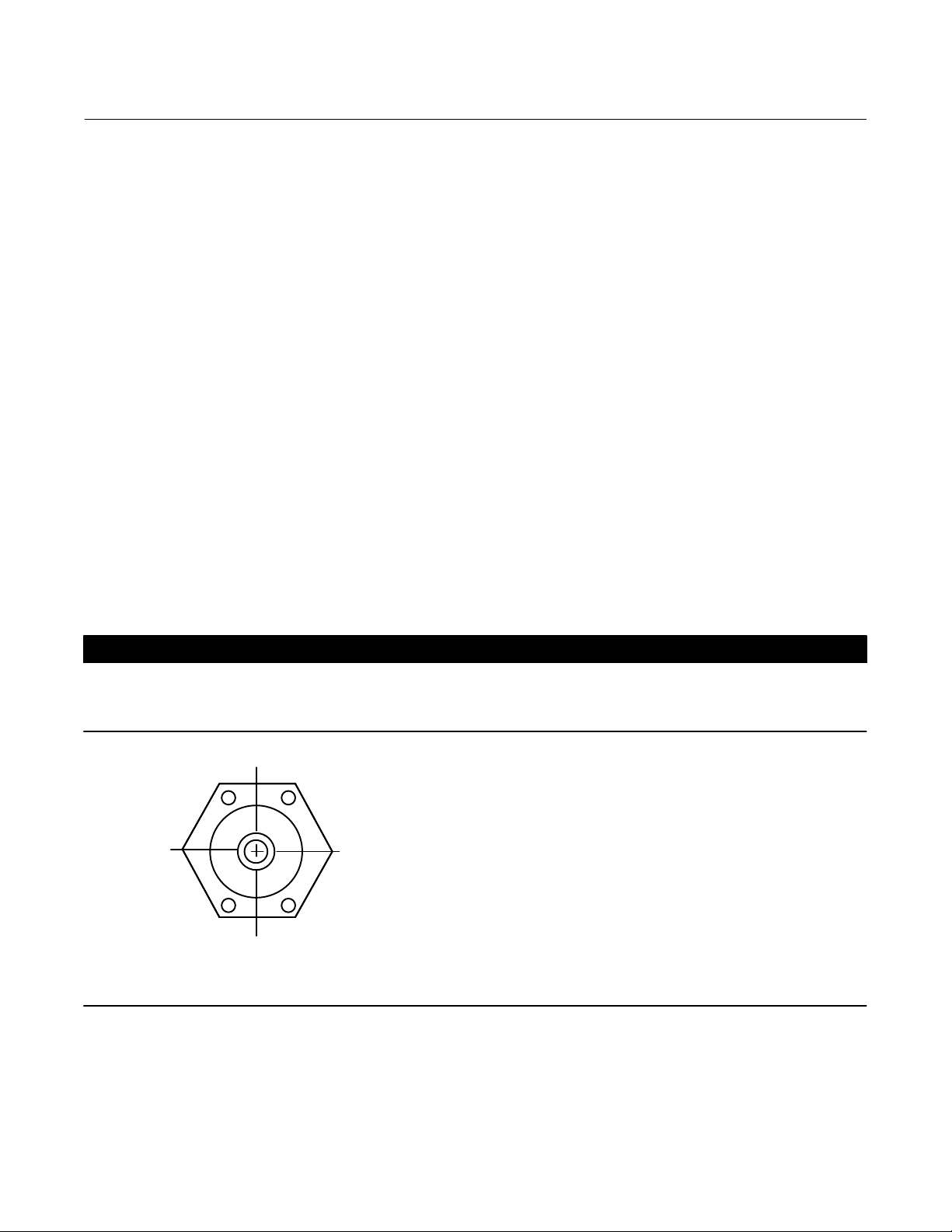
Insert the displacer end of the L2e sensor into the vessel connection and tighten enough to seal the threads. If
necessary, loosen or tighten slightly to obtain the horizontal orientation shown in figure 2. Make sure that the
controller case is level.
CAUTION
The displacer rod (key 64) is not a handle. Grasp sensor body or controller housing to lift and carry to avoid internal
component damage.
Figure 2. Sensor Orientation
CORRECT CONTROLLER MOUNTING
HOLE ORIENTATION WHEN MOUNTED ON VESSEL
A6639
 Loading...